For 1990-2009 cars only
Tools Required
| • | SA91100C Tie Rod Separator |
| • | J 43631 Ball Joint Remover |
Removal Procedure
- With the wheels in the straight ahead position, remove the key from the ignition switch.
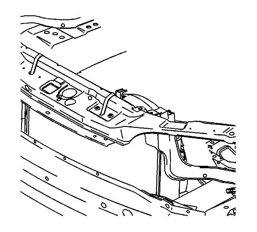
- Secure the cooling module to the upper body structure.
- Raise and support the vehicle. Refer to Lifting and Jacking the Vehicle in General Information.
- Remove the front wheels from the vehicle. Refer to Tire and Wheel Removal and Installation in Tires and Wheels.
- Remove the left and right splash shields. Refer to Engine Splash Shield Replacement .
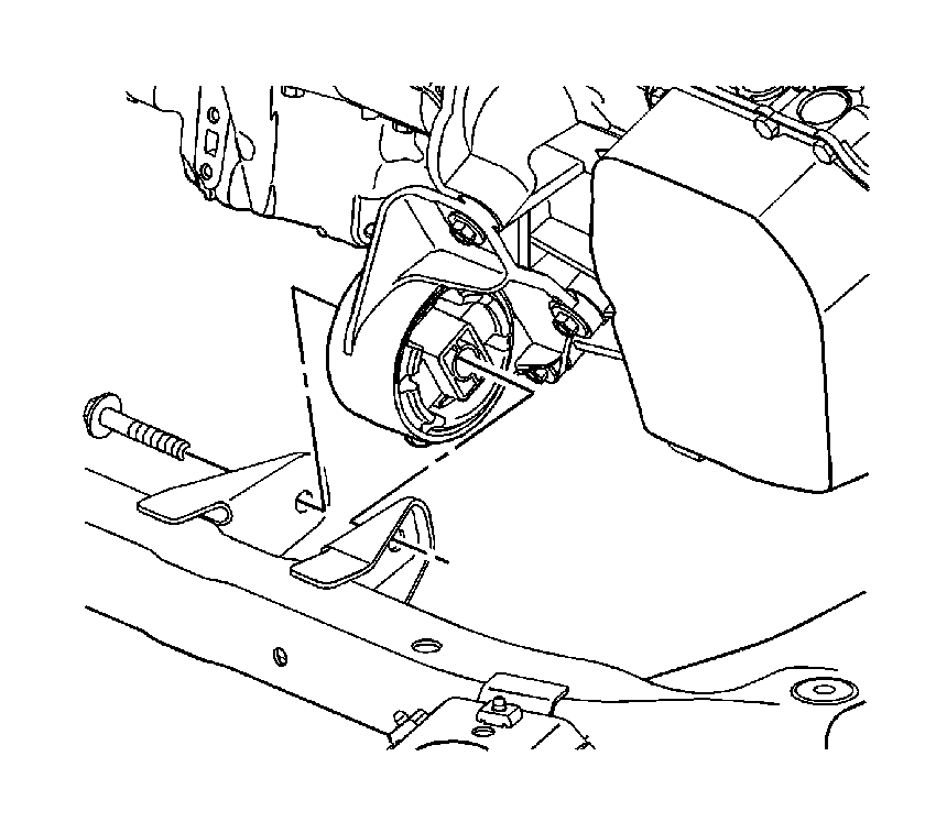
- Remove the front transaxle mount to cradle through bolt.
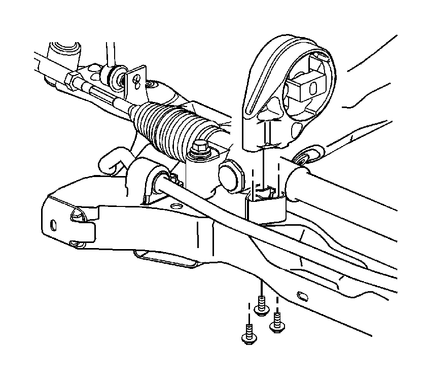
- Remove the rear transaxle mount to frame bolts.
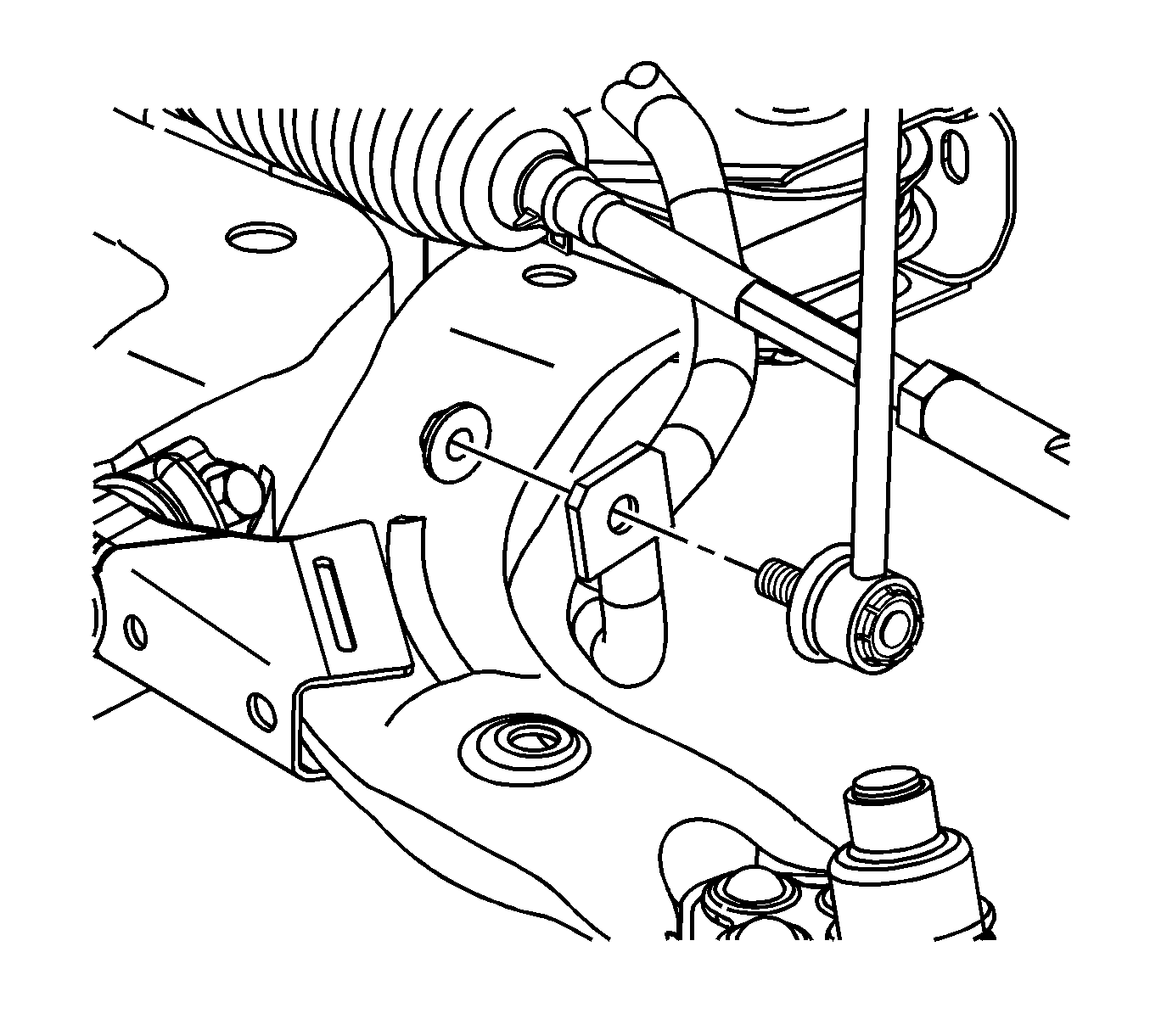
- Remove both stabilizer link to stabilizer shaft nuts. Refer to Stabilizer Shaft Link Replacement in Front Suspension.
- Remove both tie rod to steering knuckle nuts.
- Use the SA91100C to separate the outer tie rods from the steering knuckles.
- Remove the intermediate steering shaft to steering gear pinch bolt and discard.
- Disconnect the intermediate steering shaft from the steering gear.
- Remove both lower control arm ball stud to steering knuckle pinch bolts.
- Lower the lower control arms in order to disengage the steering knuckle. If necessary, use the J 43631 .
- Mark the frame to body position with a paint pen or permanent marker.
- Lower the vehicle to about three feet off the ground in order to place an hydraulic lift table under the frame.
- Use two 2 x 4s between the lift table and the frame and lift the table to the frame.
- Slowly remove the frame bolts using the following sequence:
- Slowly lower the lift table to the floor.
- Continue with the following steps when replacing the frame:
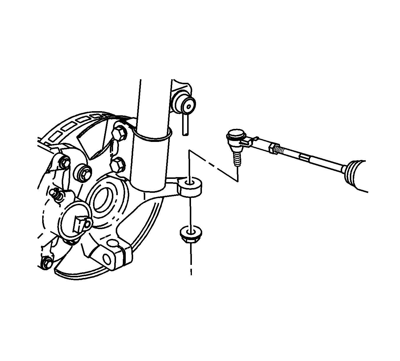
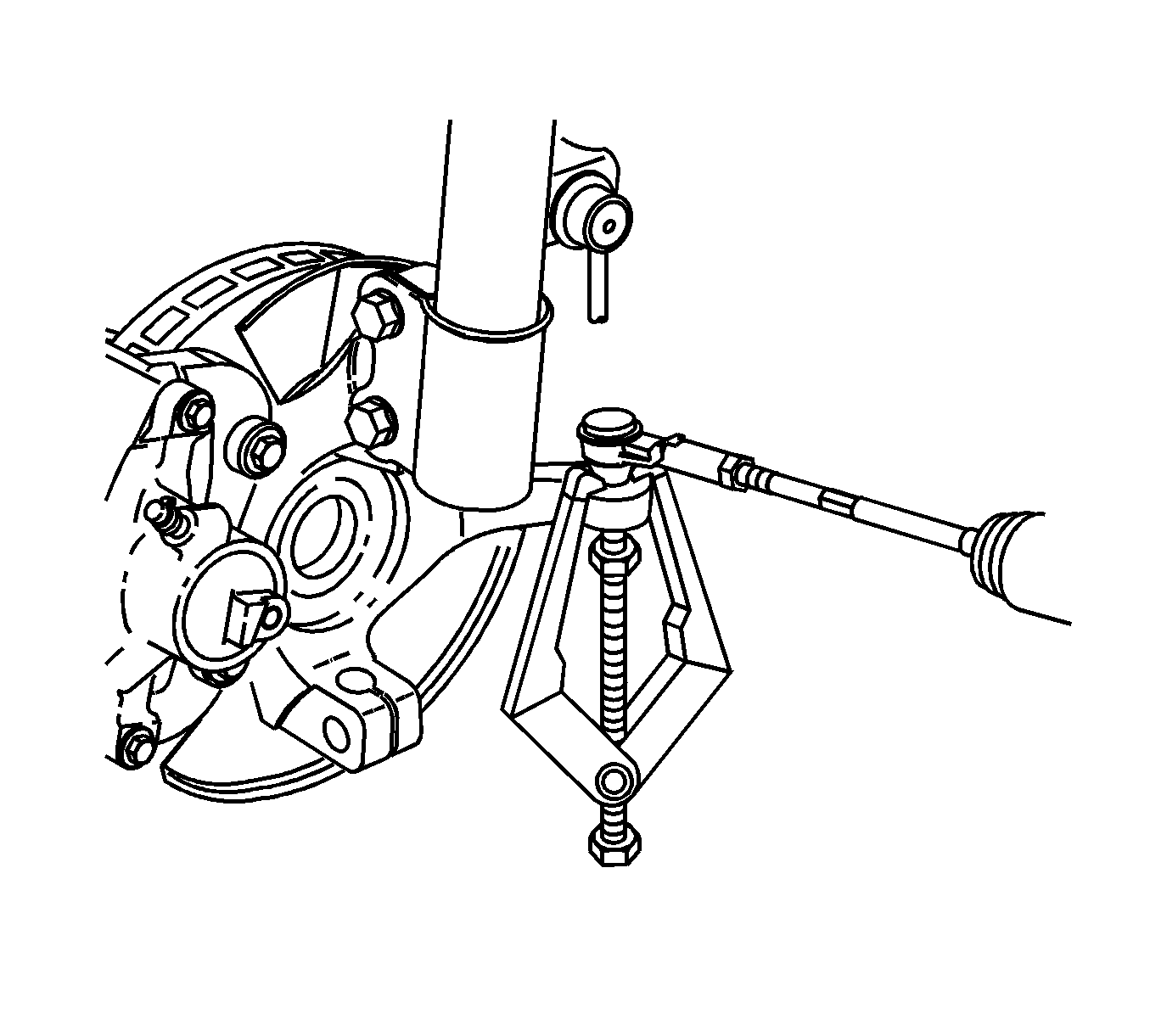
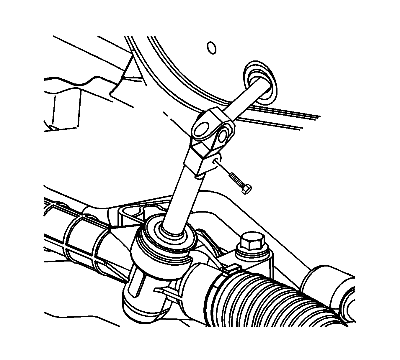
Important: DO NOT rotate the intermediate shaft once separated from the gear. Possible damage or a malfunction could occur.
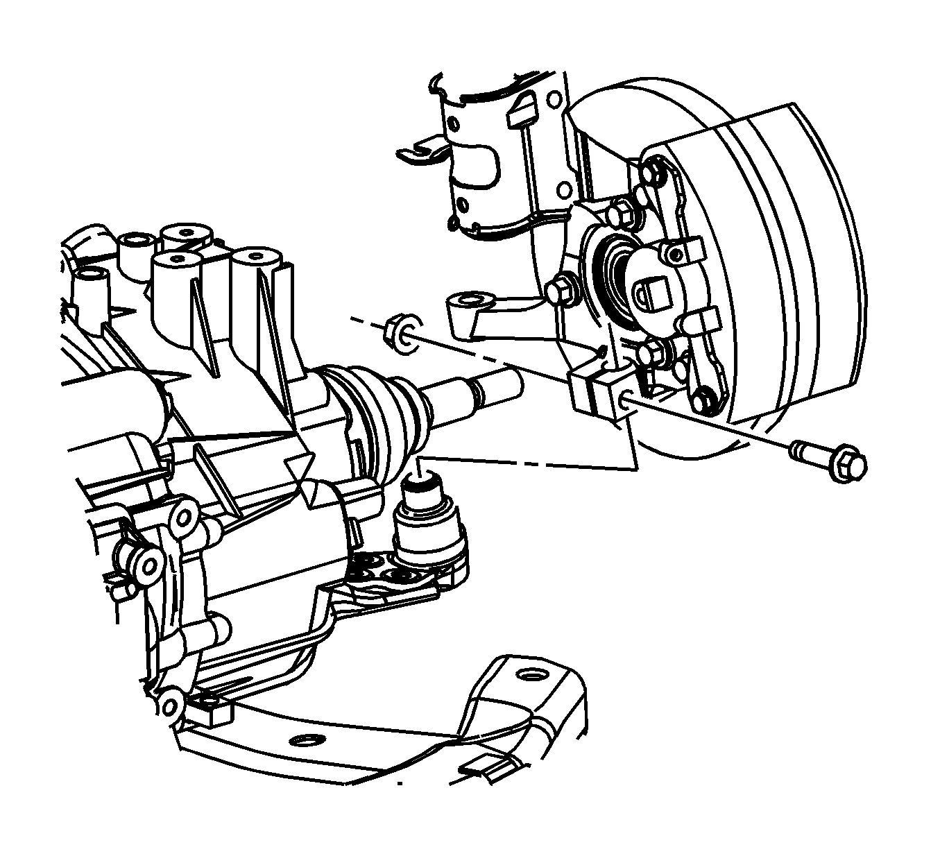
Notice: Do not free the ball stud by using a pickle fork or a wedge-type tool. Damage to the seal or bushing may result.
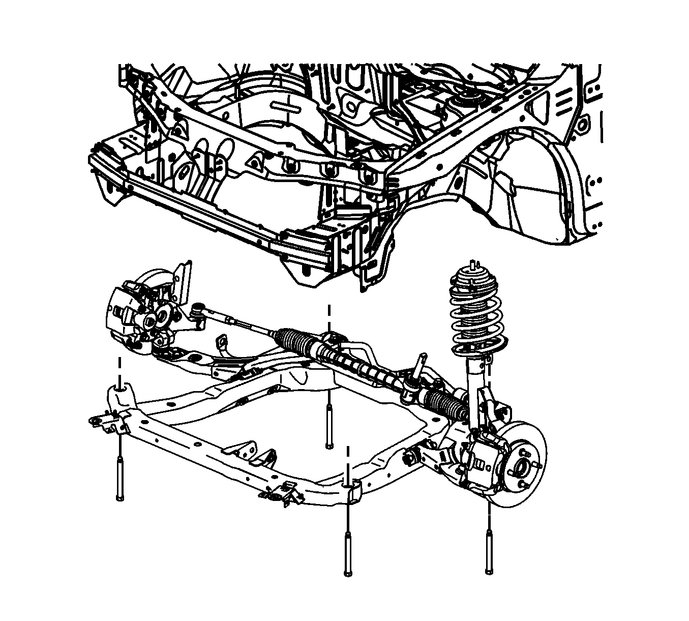
| 18.1. | Remove the front frame bolts. |
| 18.2. | Partially unscrew the rear frame bolts exposing 25.4 mm (1.5 in) of bolt shank. |
| 20.1. | Remove the steering gear from the frame. Refer to Steering Gear Replacement in Power Steering System. |
| 20.2. | Remove the stabilizer bar from the frame. Refer to Stabilizer Shaft Replacement in Front Suspension. |
| 20.3. | Remove the lower control arms from the frame. Refer to Lower Control Arm Replacement in Front Suspension. |
| 20.4. | Remove the radiator brackets from the frame. |
Installation Procedure
- If replacing the frame, perform the following steps:
- With the frame on the lift table, raise the frame to the vehicle.
- Hand start all the frame bolts while aligning the frame to the paint marks.
- Tighten the frame bolts.
- Lower and remove the hydraulic table.
- Connect the lower control arm to the steering knuckle.
- Install the ball joint pinch bolt and nut.
- First Pass: Tighten the nut to 50 N·m (37 lb ft) .
- Reverse nut 3/4 turn
- Second Pass: Tighten the nut to 50 N·m (37 lb ft) + 30 degrees.
- Hand start the front transaxle mount through bolt.
- Loosen the rear transmission mount through bolt.
- Tighten the rear transaxle mount to frame bolts.
- Tighten the front and rear transaxle mount through bolts in the following order.
- Tighten the rear bolt to 100 N·m (74 lb ft).
- Tighten the front bolt to 100 N·m (74 lb ft).
- Install the outer tie rods to the steering knuckles.
- Install the new outer tie rod to the knuckle nuts.
- Connect the stabilizer links to the stabilizer shaft. Refer to Stabilizer Shaft Link Replacement in Front Suspension.
- Connect the intermediate shaft to the steering gear.
- Install a new intermediate shaft pinch bolt.
- Install the left and right splash shields. Refer to Engine Splash Shield Replacement .
- Install the front wheels. Refer to Tire and Wheel Removal and Installation in Tires and Wheels.
- Lower the vehicle.
- Road test the vehicle in order to test for the following conditions:
| 1.1. | Install the radiator brackets to the frame. |
| 1.2. | Install the lower control arms to the frame. Refer to Lower Control Arm Replacement in Front Suspension. |
| 1.3. | Install the stabilizer bar to the frame. Refer to Stabilizer Shaft Replacement in Front Suspension. |
| 1.4. | Install the steering gear to the frame. Refer to Steering Gear Replacement in Power Steering System. |

Notice: Refer to Fastener Notice in the Preface section.
Tighten
Tighten the bolts to 100 N·m + 180 degrees (74 lb ft) + 180 degrees.

Important: The torque sequence must be followed in the order that is listed.
Tighten

Important: The front and rear transmission mounts must be allowed to settle with the through bolts loosened.

Tighten
Tighten the rear bolts to 50 N·m (37 lb ft).
Tighten

Tighten
Tighten the nuts to 20 N·m (15 lb ft) + 180 degrees.

Tighten
Tighten the bolt to 34 N·m (25 lb ft).
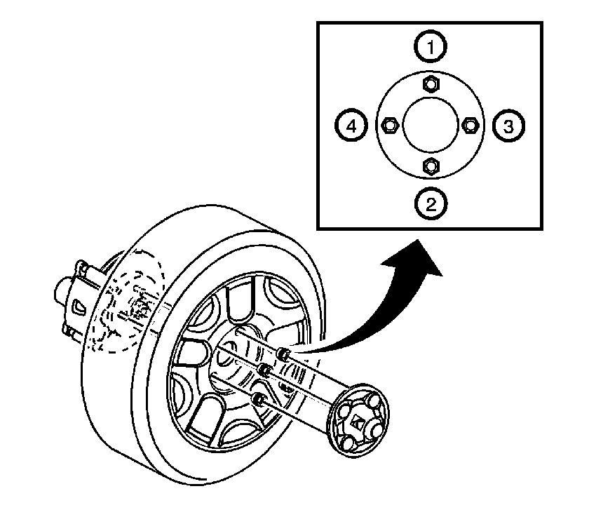
| • | Steering leads or pulls |
| • | Refer to Wheel Alignment Measurement in Wheel Alignment. |
| • | Abnormal powertrain noise or vibration at idle |
| • | Refer to Checking Frame Alignment in Frame and Underbody. |
