Tools Required
| • | J 45166 8"
Dial Indicator Extension Rod |

- Rotate the transaxle assembly so the torque
converter housing side is facing up.
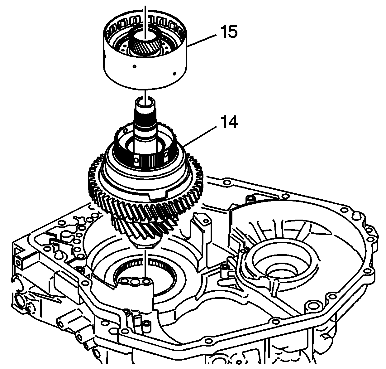
- Using the case as a holding fixture, install the front differential transfer
drive gear assembly (14) into the output gear bore.
- Install the 4-5 clutch assembly (15) onto the front differential
transfer drive gear (14), with the clutch plates facing up.

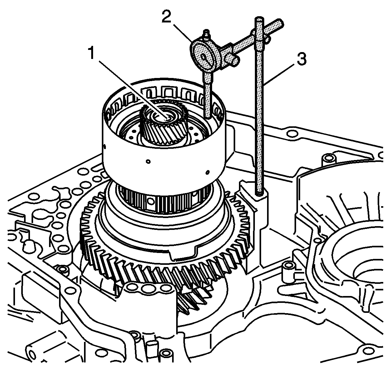
- Install the 8 mm threaded end ofJ 45166
(3) into the
case bolt hole as indicated in the graphic.
- Install J 45200
(2)
onto J 45166
(3) as
shown. Position the dial indicator pointer on the clutch piston and set the dial indicator
to zero.
- Apply air pressure to the fluid passage (1) in the end of the
4-5 clutch drum shaft, and record the measurement. Refer to 4-5 Clutch
Piston Stroke in Transmission Clearance Specifications to determine the correct backing
plate.
- Remove the 4-5 clutch drum assembly and the front differential
transfer drive gear assembly from the case.


