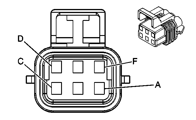
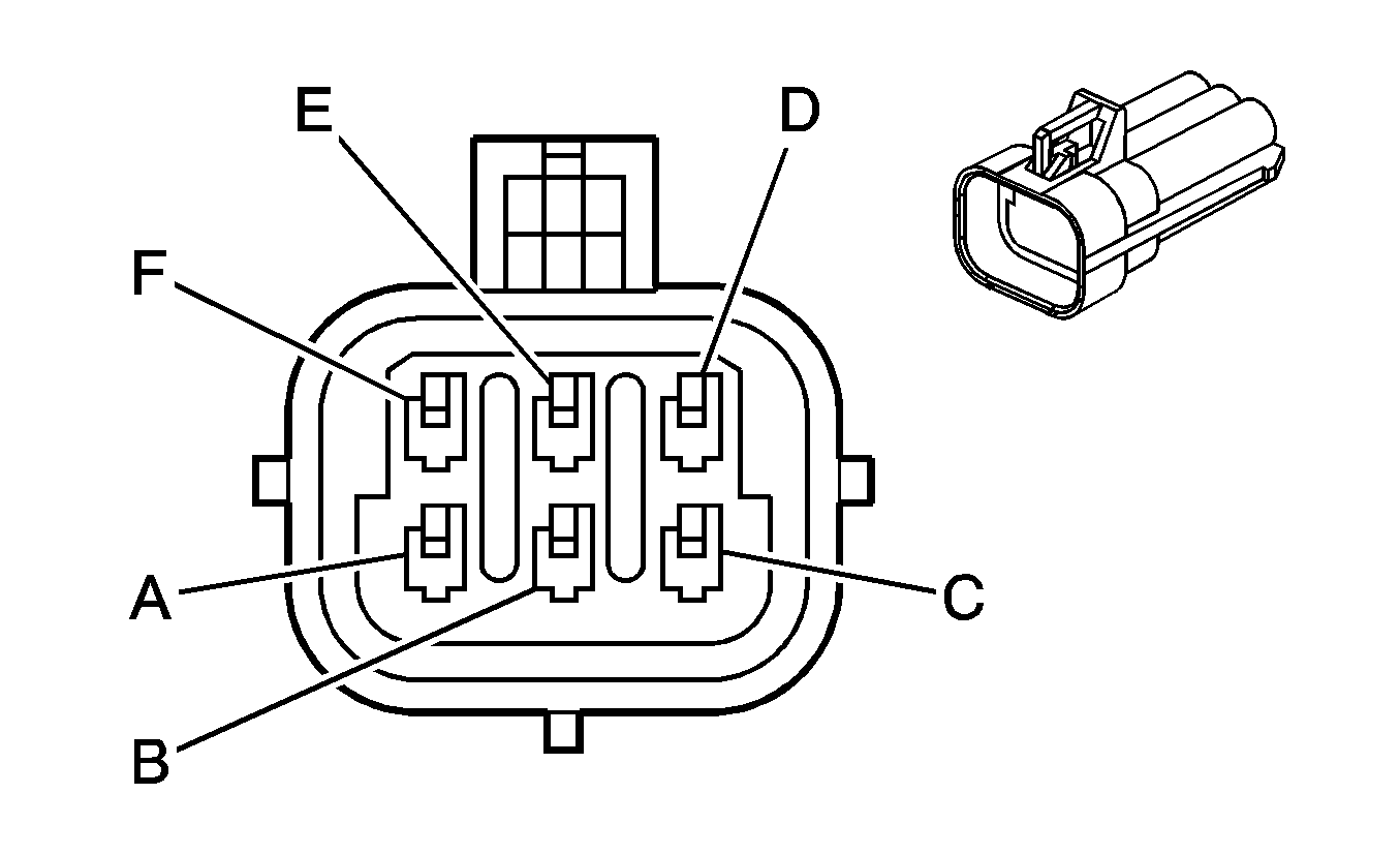
| Table 1: | C110 (Sedan) |
| Table 2: | C111 (Sedan) |
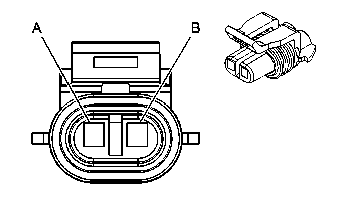
| Table 3: | C121 (DF5) |
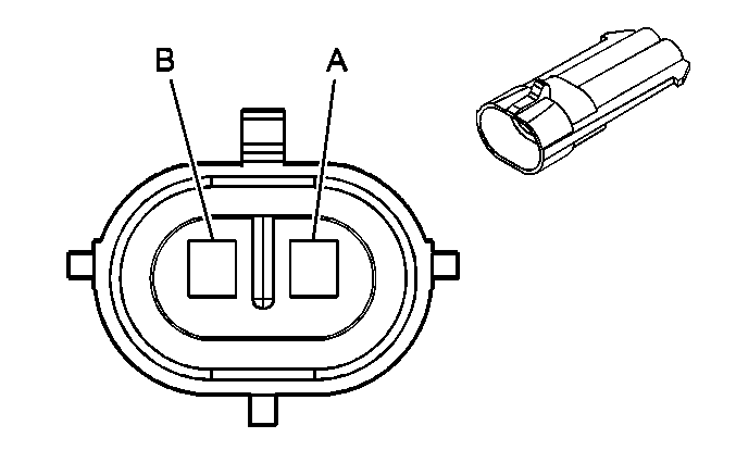
| Table 4: | C150 (2.2L) |
| Table 5: | C150 (2.0L) |
| Table 6: | C155 (2.0L) |
| Table 7: | C160 (JM4/JL9) |
| Table 8: | C161 (JM4/JL9) |
| Table 9: | C171 (2.0L) |
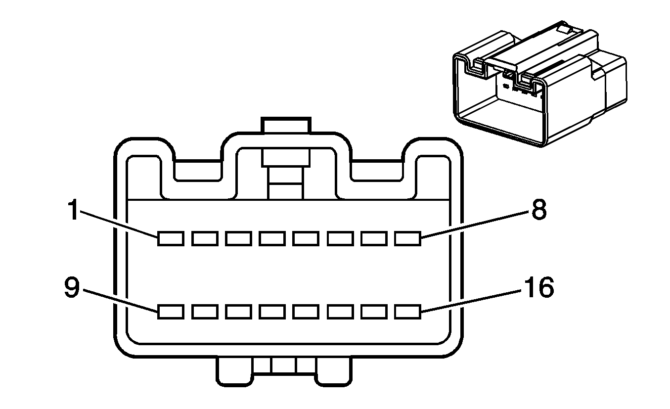
| Table 10: | C200 |
| Table 11: | C201 (2.2L) |
| Table 12: | C201 (2.0L) |
| Table 13: | C215 |
| Table 14: | C216 |
| Table 15: | C218 (ASF) |
| Table 16: | C220 (2.0L) |
| Table 17: | C225 |
| Table 18: | C235 (2.2L w/K34) |
| Table 19: | C340 (UE1/U2K) |
| Table 20: | C351 (M43/M75) |
| Table 21: | C375 (Sedan) |
| Table 22: | C375 (Coupe) |
| Table 23: | C380 (UE1) |
| Table 24: | C401 |
| Table 25: | C406 (EVAP Controls) |
| Table 26: | C406 (Rear WSS) (JM4/JL9) |
| Table 27: | C406 (Fuel Controls) |
| Table 28: | C490 |
| Table 29: | C491 |
| Table 30: | C501 (AU3) |
| Table 31: | C503 (Coupe w/A31 and DG7) |
| Table 32: | C503 (Sedan w/A31 and DG7) |
| Table 33: | C507 (w/o AU3) |
| Table 34: | C602 (AU3) |
| Table 35: | C604 (A31) |
| Table 36: | C608 (w/o AU3) |
| Table 37: | C759 (Sedan w/AU3) |
| Table 38: | C860 (Sedan w/AU3) |
|
| ||||||||||||||
|---|---|---|---|---|---|---|---|---|---|---|---|---|---|---|---|
Connector Part Information |
| Connector Part Information |
| ||||||||||||
Pin | Wire Color | Circuit No. | Function | Pin | Wire Color | Circuit No. | Function | ||||||||
A | OG | 640 | Battery Positive Voltage | A | OG | 640 | Battery Positive Voltage | ||||||||
B | BN | 9 | Park Lamp Supply Voltage | B | BN | 9 | Park Lamp Supply Voltage | ||||||||
C | D-BU | 15 | Right Turn Signal Lamps Supply Voltage | C | L-BU | 15 | Right Turn Signal Lamps Supply Voltage | ||||||||
D | PK | 1200 | Headlamp High Beam Signal | D | PK | 1200 | Headlamp High Beam Signal | ||||||||
E | D-BU | 1201 | Head Lamp Low Beam Signal | E | D-BU | 1201 | Head Lamp Low Beam Signal | ||||||||
F | BK | 150 | Ground | F | BK | 150 | Ground | ||||||||

|

| ||||||||||||||
|---|---|---|---|---|---|---|---|---|---|---|---|---|---|---|---|
Connector Part Information |
| Connector Part Information |
| ||||||||||||
Pin | Wire Color | Circuit No. | Function | Pin | Wire Color | Circuit No. | Function | ||||||||
A | OG | 740 | Battery Positive Voltage | A | OG | 640 | Battery Positive Voltage | ||||||||
B | BN | 9 | Park Lamp Supply Voltage | B | BN | 9 | Park Lamp Supply Voltage | ||||||||
C | L-BU | 14 | Left Turn Signal Lamps Supply Voltage | C | L-BU | 15 | Left Turn Signal Lamps Supply Voltage | ||||||||
D | PK | 1200 | Headlamp High Beam Signal | D | PK | 1200 | Headlamp High Beam Signal | ||||||||
E | D-BU | 1201 | Headlamp Low Beam Signal | E | D-BU | 1201 | Headlamp Low Beam Signal | ||||||||
F | BK | 150 | Ground | F | BK | 150 | Ground | ||||||||
|
| ||||||||||||||||||
|---|---|---|---|---|---|---|---|---|---|---|---|---|---|---|---|---|---|---|---|
Connector Part Information |
| Connector Part Information |
| ||||||||||||||||
Pin | Wire Color | Circuit No. | Function | Pin | Wire Color | Circuit No. | Function | ||||||||||||
A | L-GN/BK | 735 | Ambient Air Temperature Sensor | A | L-GN/BK | 735 | Ambient Air Temperature Sensor Signal | ||||||||||||
B | GY/BK | 1798 | Low Reference | B | L-GN/BK | 1798 | Low Reference | ||||||||||||
|
| ||||||||||||||
|---|---|---|---|---|---|---|---|---|---|---|---|---|---|---|---|
Connector Part Information |
| Connector Part Information |
| ||||||||||||
Pin | Wire Color | Circuit No. | Function | Pin | Wire Color | Circuit No. | Function | ||||||||
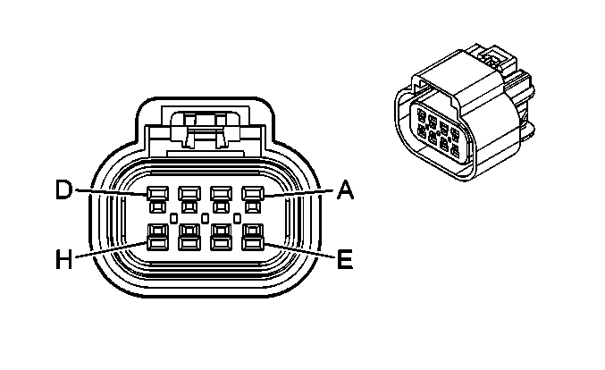
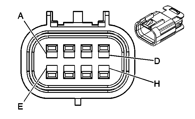
A | BK | 1744 | Fuel Injector 1 Control | A | BK | 1744 | Fuel Injector 1 Control | ||||||||
B | L-GN/BK | 1745 | Fuel Injector 2 Control | B | L-GN/BK | 1745 | Fuel Injector 2 Control | ||||||||
C | PK/BK | 1746 | Fuel Injector 3 Control | C | PK/BK | 1746 | Fuel Injector 3 Control | ||||||||
D | L-BU/BK | 844 | Fuel Injector 4 Control | D | L-BU/BK | 844 | Fuel Injector 4 Control | ||||||||
E | PK | 839 | Ignition 1 Voltage | E | PK | 139 | Ignition 1 Voltage | ||||||||
F | OR/BK | 469 | Low Reference | F | OR/BK | 469 | Low Reference | ||||||||
G | L-GN | 432 | MAP Sensor Signal | G | L-GN | 432 | MAP Sensor Signal | ||||||||
H | GY | 2704 | 5-Volt Reference | H | GY | 2704 | 5-Volt Reference | ||||||||
|
| ||||||||||||||
|---|---|---|---|---|---|---|---|---|---|---|---|---|---|---|---|
Connector Part Information |
| Connector Part Information |
| ||||||||||||
Pin | Wire Color | Circuit No. | Function | Pin | Wire Color | Circuit No. | Function | ||||||||
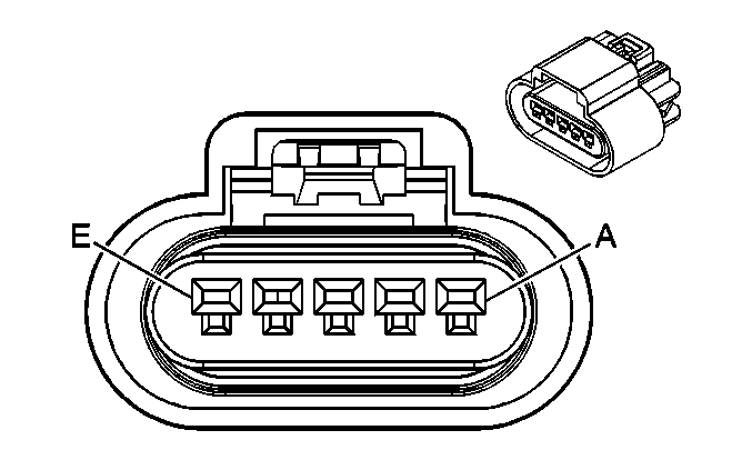
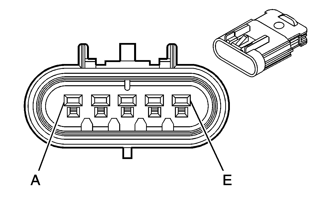
A | PK/BK | 5293 | Ignition 1 Voltage | A | PK/BK | 5293 | Ignition 1 Voltage | ||||||||
B | BK | 1744 | Fuel Injector 1 Control | B | BK | 1744 | Fuel Injector 1 Control | ||||||||
C | L-GN/BK | 1745 | Fuel Injector 2 Control | C | L-GN/BK | 1745 | Fuel Injector 2 Control | ||||||||
D | PK/BK | 1746 | Fuel Injector 3 Control | D | PK/BK | 1746 | Fuel Injector 3 Control | ||||||||
E | L-BU/BK | 844 | Fuel Injector 4 Control | E | L-BU/BK | 844 | Fuel Injector 4 Control | ||||||||

|

| ||||||||||||||
|---|---|---|---|---|---|---|---|---|---|---|---|---|---|---|---|
Connector Part Information |
| Connector Part Information |
| ||||||||||||
Pin | Wire Color | Circuit No. | Function | Pin | Wire Color | Circuit No. | Function | ||||||||
A | PK/BK | 5292 | Ignition 1 Voltage | A | PK/BK | 5292 | Ignition 1 Voltage | ||||||||
B | PU | 6413 | Low Reference | B | VT | 6413 | Low Reference | ||||||||
C | BN/WH | 6405 | IC 1 Control | C | TN/WH | 6405 | IC 1 Control | ||||||||
D | D-BU/WH | 6406 | IC 3 Control | D | D-BU/WH | 6406 | IC 3 Control | ||||||||
E | D-GN/WH | 6407 | IC 4 Control | E | D-GN/WH | 6407 | IC 4 Control | ||||||||
F | L-BU/WH | 6408 | IC 2 Control | F | L-BU/WH | 6408 | IC 2 Control | ||||||||
G | BK/WH | 451 | Ground | G | BK/WH | 451 | Ground | ||||||||
H | -- | -- | Not Used | H | -- | -- | Not Used | ||||||||

|

| ||||||||||||||
|---|---|---|---|---|---|---|---|---|---|---|---|---|---|---|---|
Connector Part Information |
| Connector Part Information |
| ||||||||||||
Pin | Wire Color | Circuit No. | Function | Pin | Wire Color | Circuit No. | Function | ||||||||
A | D-GN | 872 | Right Front Wheel Speed Sensor Signal | A | L-BU | 872 | Right Front Wheel Speed Sensor Signal | ||||||||
B | TN | 833 | Right Front Wheel Speed Sensor Low Reference | B | YE | 833 | Right Front Wheel Speed Sensor Low Reference | ||||||||

|

| ||||||||||||||
|---|---|---|---|---|---|---|---|---|---|---|---|---|---|---|---|
Connector Part Information |
| Connector Part Information |
| ||||||||||||
Pin | Wire Color | Circuit No. | Function | Pin | Wire Color | Circuit No. | Function | ||||||||
A | L-BU | 830 | Left Front Wheel Speed Sensor Signal | A | L-BU | 872 | Left Front Wheel Speed Sensor Signal | ||||||||
B | YE | 873 | Left Front Wheel Speed Sensor Low Reference | B | YE | 833 | Left Front Wheel Speed Sensor Low Reference | ||||||||

|

| ||||||||||||||
|---|---|---|---|---|---|---|---|---|---|---|---|---|---|---|---|
Connector Part Information |
| Connector Part Information |
| ||||||||||||
Pin | Wire Color | Circuit No. | Function | Pin | Wire Color | Circuit No. | Function | ||||||||
A | -- | -- | Not Used | A | -- | -- | Not Used | ||||||||
B | L-BU | 6118 | IAT 2 Sensor Signal | B | L-BU | 6118 | IAT 2 Sensor Signal | ||||||||
C | D-GN | 335 | Low Speed Cooling Fan Relay Control | C | D-GN | 335 | Low Speed Cooling Fan Relay Control | ||||||||
D | D-BU | 473 | High Speed Cooling Fan Relay Control | D | D-BU | 473 | High Speed Cooling Fan Relay Control | ||||||||
E | GY | 2700 | 5-Volt Reference | E | GY | 2700 | 5-Volt Reference | ||||||||
F | RD/BK | 380 | A/C Refrigerant Pressure Sensor Signal | F | RD/BK | 380 | A/C Refrigerant Pressure Sensor Signal | ||||||||
G | BK | 2751 | Low Reference | G | BK | 2751 | Low Reference | ||||||||
H | PK/BK | 5290 | Ignition 1 Voltage | H | PK/BK | 5290 | Ignition 1 Voltage | ||||||||
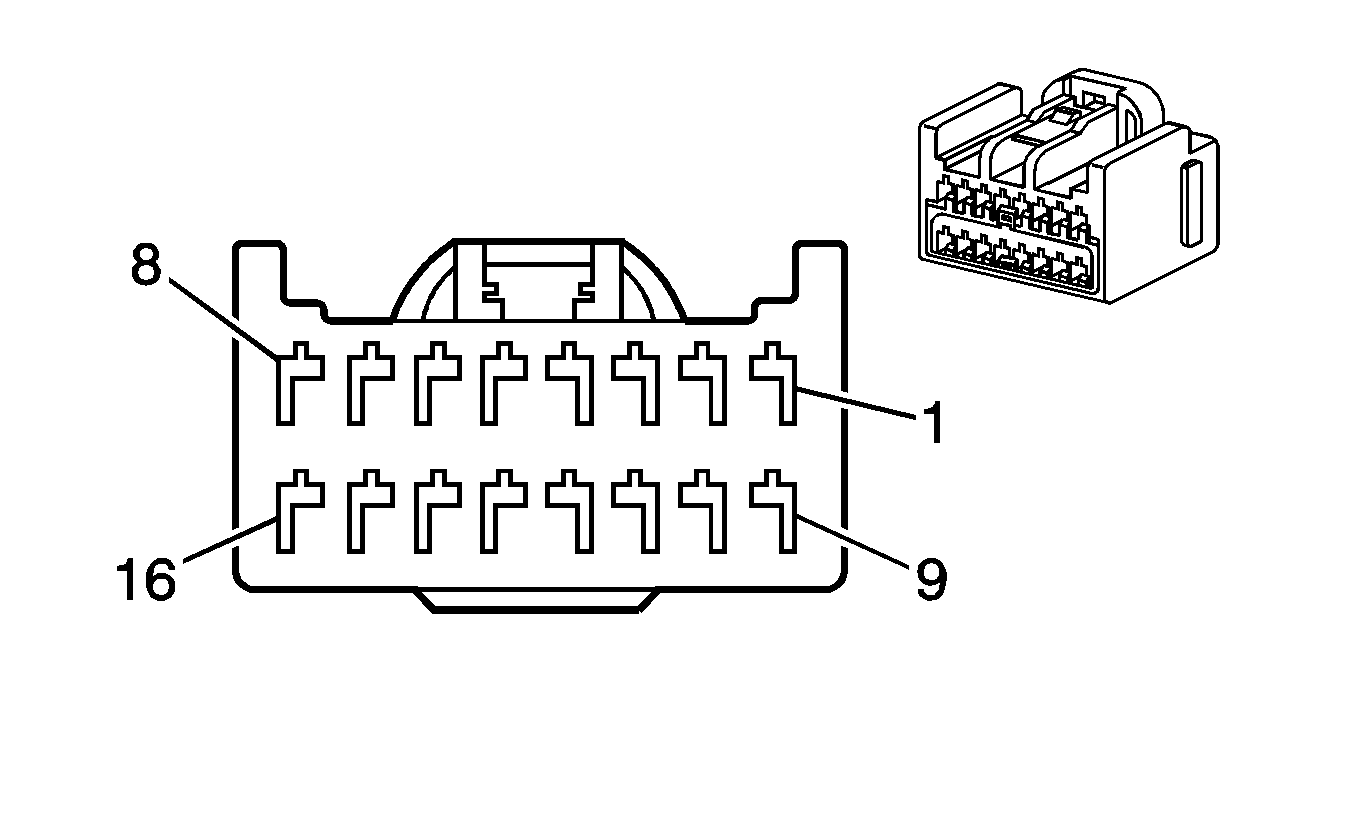
|
| ||||||||||||||
|---|---|---|---|---|---|---|---|---|---|---|---|---|---|---|---|
Connector Part Information |
| Connector Part Information |
| ||||||||||||
Pin | Wire Color | Circuit No. | Function | Pin | Wire Color | Circuit No. | Function | ||||||||
1 | L-BU | 115 | Right Rear Speaker Output (-) | 1 | L-BU | 115 | Right Rear Speaker Output (-) | ||||||||
2 | D-BU | 46 | Right Rear Speaker Output (+) | 2 | D-BU | 46 | Right Rear Speaker Output (+) | ||||||||
3 | YE | 116 | Left Rear Speaker Output (-) | 3 | YE | 116 | Left Rear Speaker Output (-) | ||||||||
4 | BN | 199 | Left Rear Speaker Output (+) | 4 | BN | 199 | Left Rear Speaker Door Output (+) | ||||||||
5 | D-GN | 117 | Right Front Speaker Output (-) | 5 | D-GN | 117 | Right Front Speaker Door Output (-) | ||||||||
6 | L-GN | 200 | Right Front Speaker Output (+) | 6 | L-GN | 200 | Right Front Speaker Door Output (+) | ||||||||
7 | GY | 118 | Left Front Speaker Output (-) | 7 | GY | 118 | Left Front Speaker Door Output (-) | ||||||||
8 | TN | 201 | Left Front Speaker Output (+) | 8 | TN | 201 | Left Front Speaker Door Output (+) | ||||||||
9 | PK | 314 | Radio On Signal | 9 | PK | 314 | Radio On Signal (UZ6) | ||||||||
10 | L-BU | 1957 | Left Front Midrange Speaker Output (-) | 10 | GY | 118 | Left Front Speaker Output (-) (UZ6) | ||||||||
10 | L-BU | 1957 | Left Front Midrange Speaker Output (-) (U79/UX7) | ||||||||||||
11 | D-BU | 1857 | Left Front Midrange Speaker Output (+) | 11 | TN | 201 | Left Front Speaker Output (+) (UZ6) | ||||||||
11 | D-BU | 1857 | Left Front Midrange Speaker Output (+) (U79/UX7) | ||||||||||||
12 | TN | 2133 | Side Impact Sensing Module - Right - Voltage | 12 | TN | 2133 | Side Impact Sensing Module - Right - Voltage | ||||||||
13 | D-GN | 2134 | Side Impact Sensing Module - Right - Voltage | 13 | D-GN | 2134 | Side Impact Sensing Module - Right - Voltage | ||||||||
14 | L-GN | 2116 | Seat Belt Pretensioner - Right - High Control | 14 | L-GN | 2116 | Seat Belt Pretensioner - Right - High Control | ||||||||
15 | OG | 2117 | Seat Belt Pretensioner - Right - Low Control | 15 | OG | 2117 | Seat Belt Pretensioner - Right - Low Control | ||||||||
16 | -- | -- | Not Used | 16 | -- | -- | Not Used | ||||||||
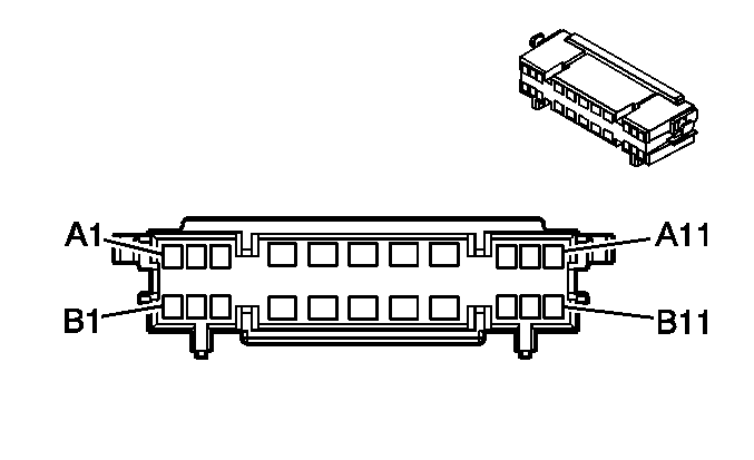
|
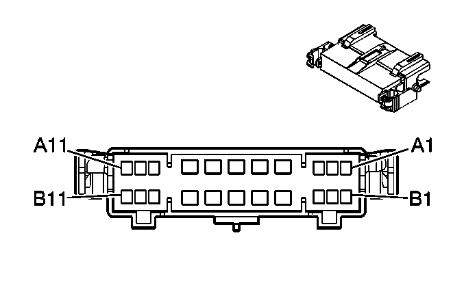
| ||||||||||||||
|---|---|---|---|---|---|---|---|---|---|---|---|---|---|---|---|
Connector Part Information |
| Connector Part Information |
| ||||||||||||
Pin | Wire Color | Circuit No. | Function | Pin | Wire Color | Circuit No. | Function | ||||||||
A1 | PU | 420 | Stop Lamp Switch Signal | A1 | PU | 420 | Stop Lamp Switch Signal | ||||||||
A2 | -- | -- | Not Used | A2 | -- | -- | Not Used | ||||||||
A3 | BK/WH | 56 | Supply Voltage | A3 | BK/WH | 56 | Valet Switch Release Actuator | ||||||||
A4 | TN/WH | 2500 | High Speed GM LAN Serial Data Bus (+) | A4 | TN/WH | 2500 | High Speed GM LAN Serial Data Bus (+) | ||||||||
A5 | TN | 2501 | High Speed GM LAN Serial Data Bus (-) | A5 | TN | 2501 | High Speed GM LAN Serial Data Bus (-) | ||||||||
A6 | OG | 1140 | Battery Positive Voltage | A6 | OG | 1140 | Battery Positive Voltage | ||||||||
OG | 1140 | Battery Positive Voltage | |||||||||||||
A7 | BK/WH | 2118 | Seat Belt Pretensioner - Left - High Control | A7 | BK/WH | 2118 | Seat Belt Pretensioner - Left - Front | ||||||||
A8 | OG/BK | 2119 | Seat Belt Pretensioner - Left - Low Control | A8 | OG/BK | 2119 | Seat Belt Pretensioner - Left - Front | ||||||||
A9 | -- | -- | Not Used | A9 | -- | -- | Not Used | ||||||||
A10 | L-BU | 1957 | Left Front Speaker Output (+) | A10 | L-BU | 1957 | Left Front Door Tweeter Speaker (-) | ||||||||
A11 | D-BU | 1857 | Left Front Midrange Speaker Output (-) | A11 | D-BU | 1857 | Left Front Door Speaker (+) | ||||||||
B1 | -- | -- | Not Used | B1 | -- | -- | Not Used | ||||||||
B2 | L-GN | 1715 | Windshield Wiper Switch High Signal | B2 | L-GN | 1715 | Windshield Wiper Switch High Signal Power Voltage | ||||||||
B3 | YE | 575 | Starter Control | B3 | YE | 575 | Starter Control | ||||||||
B4 | BN/WH | 419 | Malfunction Indicator Lamp (MIL) Control | B4 | BN/WH | 419 | MIL Control | ||||||||
B5 | L-BU | 1888 | Cruise Control Servo Clutch Control | B5 | L-BU | 1888 | Cruise Control Servo Clutch Control | ||||||||
B6 | L-GN | 1887 | Cruise Control Servo Move Direction Signal | B6 | L-GN | 1887 | Cruise Control Servo Move Direction Signal | ||||||||
B7 | PK | 1886 | Cruise Control Servo Move Signal | B7 | PK | 1886 | Cruise Control Servo Move Signal | ||||||||
B8 | GY | 1884 | Cruise Control Set/Coast and Resume/Accelerate Switch Signal | B8 | GY | 1884 | Cruise Control Set/Coast and Resume/Accelerate Switch Signal | ||||||||
B9 | WH | 2132 | Side Impact Sensing Module - Left - Signal | B9 | WH | 2132 | Inflatable Restraint Side Impact Sensor - Left | ||||||||
B10 | YE | 2131 | Side Impact Sensing Module - Left - Voltage | B10 | YE | 2131 | Inflatable Restraint Side Impact Sensor - Left Signal | ||||||||
B11 | -- | -- | Not Used | B11 | -- | -- | Not Used | ||||||||

|

| ||||||||||||||
|---|---|---|---|---|---|---|---|---|---|---|---|---|---|---|---|
Connector Part Information |
| Connector Part Information |
| ||||||||||||
Pin | Wire Color | Circuit No. | Function | Pin | Wire Color | Circuit No. | Function | ||||||||
A1 | PU | 420 | Stop Lamp Switch Signal | A1 | PU | 420 | Stop Lamp Switch Signal | ||||||||
A2 | BN/WH | 419 | MIL Control | A2 | BN/WH | 419 | MIL Control | ||||||||
A3 | BK/WH | 56 | Rear Compartment Lid Release Switch | A3 | BK/WH | 56 | Rear Compartment Lid Release Switch | ||||||||
A4-A5 | -- | -- | Not Used | A4-A5 | -- | -- | Not Used | ||||||||
A6 | OG | 1140 | Battery Positive Voltage | A6 | OG | 1140 | Battery Positive Voltage | ||||||||
OG | 1140 | Battery Positive Voltage | |||||||||||||
A7 | BK/WH | 2118 | Seat Belt Pretensioner - Left - High Control | A7 | BK/WH | 2118 | Seat Belt Pretensioner - Left - High Control | ||||||||
A8 | OG/BK | 2119 | Seat Belt Pretensioner - Left - Low Control | A8 | OG/BK | 2119 | Seat Belt Pretensioner - Left - Front | ||||||||
A9 | WH/BK | 1164 | 5-Volt Reference | A9 | WH/BK | 1164 | 5-Volt Reference | ||||||||
A10 | BN | 1271 | Low Reference | A10 | BN | 1271 | Low Reference | ||||||||
A11 | D-BU | 1161 | APP Sensor 1 Signal | A11 | D-BU | 1161 | APP Sensor 1 Signal | ||||||||
B1 | BN/WH | 379 | CPP Switch Signal | B1 | BN/WH | 379 | CPP Switch Signal | ||||||||
B2 | L-GN | 1715 | Windshield Wiper Switch High Signal | B2 | L-GN | 1715 | Windshield Wiper Switch High Signal | ||||||||
B3 | YE | 575 | Starter Control | B3 | YE | 575 | Starter Control | ||||||||
B4 | YE | 2131 | Side Impact Sensing Module - Left -Voltage | B4 | YE | 2131 | Side Impact Sensing Module - Left -Voltage | ||||||||
B5 | WH | 2132 | Side Impact Sensing Module - Left - Signal | B5 | WH | 2132 | Side Impact Sensing Module - Left - Signal | ||||||||
B6 | L-BU | 1957 | Left Front Midrange Speaker Output (-) | B6 | L-BU | 1957 | Left Front Midrange Speaker Output (-) | ||||||||
B7 | D-BU | 1857 | Left Front Midrange Speaker Output (+) | B7 | D-BU | 1857 | Left Front Midrange Speaker Output (+) | ||||||||
B8 | GY | 1884 | Cruise Control Set/Coast and Resume/Accelerate Switch Signal | B8 | GY | 1884 | Cruise Control Set/Coast and Resume/Accelerate Switch Signal | ||||||||
B9 | TN | 1274 | 5-Volt Reference | B9 | TN | 1274 | 5-Volt Reference | ||||||||
B10 | PU | 1272 | Low Reference | B10 | PU | 1272 | Low Reference | ||||||||
B11 | L-BU | 1162 | APP Sensor 2 Signal | B11 | L-BU | 1162 | APP Sensor 2 Signal | ||||||||
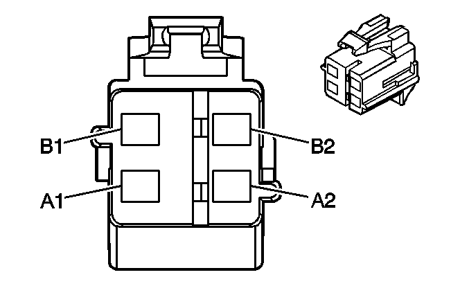
|
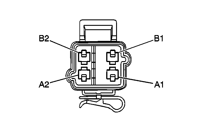
| ||||||||||||||
|---|---|---|---|---|---|---|---|---|---|---|---|---|---|---|---|
Connector Part Information |
| Connector Part Information |
| ||||||||||||
Pin | Wire Color | Circuit No. | Function | Pin | Wire Color | Circuit No. | Function | ||||||||
A1 | BN | 3020 | Steering Wheel Module - Stage 1 - Low Control | A1 | BN | 3020 | Steering Wheel Module - Stage 1 - Low Control | ||||||||
A2 | TN | 3021 | Steering Wheel Module - Stage 1 - High Control | A2 | TN | 3021 | Steering Wheel Module - Stage 1 - High Control | ||||||||
B1 | PK | 3022 | Steering Wheel Module - Stage 2 - Low Control | B1 | PK | 3022 | Steering Wheel Module - Stage 2 - Low Control | ||||||||
B2 | WH | 3023 | Steering Wheel Module - Stage 2 - High Control | B2 | WH | 3023 | Steering Wheel Module - Stage 2 - High Control | ||||||||

|

| ||||||||||||||
|---|---|---|---|---|---|---|---|---|---|---|---|---|---|---|---|
Connector Part Information |
| Connector Part Information |
| ||||||||||||
Pin | Wire Color | Circuit No. | Function | Pin | Wire Color | Circuit No. | Function | ||||||||
A1 | L-GN/RD | 3024 | I/P Module - Stage 1 - High Control | A1 | OG | 3024 | I/P Module - Stage 1 - High Control | ||||||||
A2 | RD/WH | 3025 | I/P Module - Stage 1 - Low Control | A2 | YE | 3025 | I/P Module - Stage 1 - Low Control | ||||||||
B1 | PK/BK | 3026 | I/P Module - Stage 2 - Low Control | B1 | PU | 3026 | I/P Module - Stage 2 - Low Control | ||||||||
B2 | L-BU/OG | 3027 | I/P Module - Stage 2 - High Control | B2 | GY | 3027 | I/P Module - Stage 2 - High Control | ||||||||

|
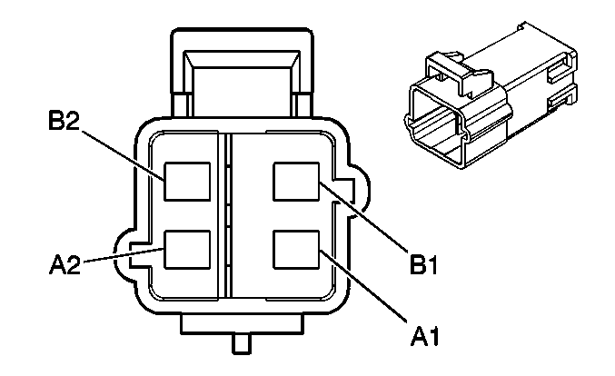
| ||||||||||||||
|---|---|---|---|---|---|---|---|---|---|---|---|---|---|---|---|
Connector Part Information |
| Connector Part Information |
| ||||||||||||
Pin | Wire Color | Circuit No. | Function | Pin | Wire Color | Circuit No. | Function | ||||||||
A1 | PU/WH | 5019 | Roof Rail Module - Left - High Control | A1 | PU/WH | 5019 | Roof Rail Module - Left - High Control | ||||||||
A2 | PK | 5020 | Roof Rail Module - Left - Low Control | A2 | PK | 5020 | Roof Rail Module - Left - Low Control | ||||||||
B1 | YE/BK | 5021 | Roof Rail Module - Right - High Control | B1 | YE/BK | 5021 | Roof Rail Module - Right - High Control | ||||||||
B2 | WH/BK | 5022 | Roof Rail Module - Right - Low Control | B2 | WH/BK | 5022 | Roof Rail Module - Right - Low Control | ||||||||
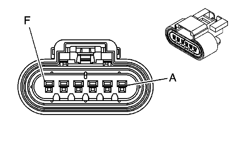
|
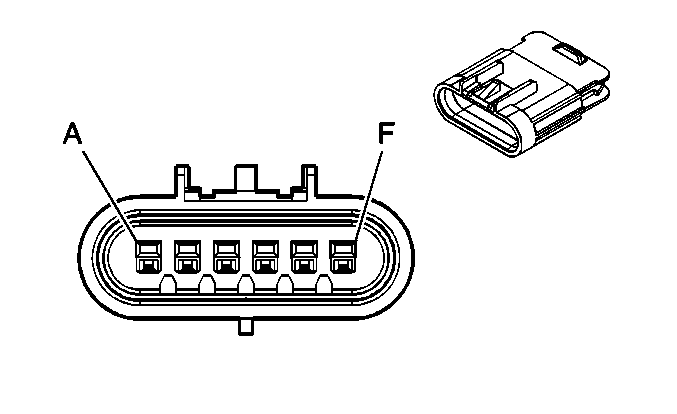
| ||||||||||||||
|---|---|---|---|---|---|---|---|---|---|---|---|---|---|---|---|
Connector Part Information |
| Connector Part Information |
| ||||||||||||
Pin | Wire Color | Circuit No. | Function | Pin | Wire Color | Circuit No. | Function | ||||||||
A | TN | 1274 | 5-Volt Reference | A | TN | 1274 | 5-Volt Reference | ||||||||
B | L-BU | 1162 | APP Sensor 2 Signal | B | L-BU | 1162 | APP Sensor 2 Signal | ||||||||
C | PU | 1272 | Low Reference | C | PU | 1272 | Low Reference | ||||||||
D | BN | 1271 | Low Reference | D | BN | 1271 | Low Reference | ||||||||
E | D-BU | 1161 | APP Sensor 1 Signal | E | D-BU | 1161 | APP Sensor 1 Signal | ||||||||
F | WH/BK | 1164 | 5-Volt Reference | F | WH/BK | 1164 | 5-Volt Reference | ||||||||

| |||||||||||||||
|---|---|---|---|---|---|---|---|---|---|---|---|---|---|---|---|
Connector Part Information |
| Connector Part Information |
| ||||||||||||
Pin | Wire Color | Circuit No. | Function | Pin | Wire Color | Circuit No. | Function | ||||||||
A | OG | 140 | Battery Positive Voltage | A | OG | 140 | Battery Positive Voltage | ||||||||
B | L-BU | 20 | Stop Lamp Switch Signal | B | L-BU | 20 | Stop Lamp Switch Signal | ||||||||
C | PK | 339 | Ignition 1 Voltage | C | PK | 339 | Ignition 1 Voltage | ||||||||
D | PU | 420 | Stop Lamp Switch Signal | D | PU | 420 | Stop Lamp Switch Signal | ||||||||
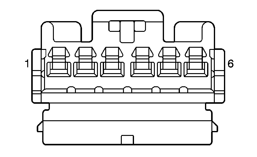
|
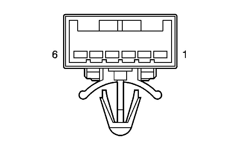
| ||||||||||||||
|---|---|---|---|---|---|---|---|---|---|---|---|---|---|---|---|
Connector Part Information |
| Connector Part Information |
| ||||||||||||
Pin | Wire Color | Circuit No. | Function | Pin | Wire Color | Circuit No. | Function | ||||||||
1 | PK | 339 | Ignition 1 Voltage | 1 | BK | 339 | Ignition 1 Voltage | ||||||||
2 | L-BU | 1888 | Cruise Control Servo Clutch Control | 2 | BK | 1888 | Cruise Control Servo Clutch Control | ||||||||
3 | PU | 420 | Stop Lamp Switch - Lower | 3 | BK | 420 | Stop Lamp Switch - Lower | ||||||||
4 | PK | 1886 | Cruise Control Servo Move Signal | 4 | BK | 1886 | Cruise Control Servo Move Signal | ||||||||
5 | BK | 550 | Ground | 5 | BK | 550 | Ground | ||||||||
6 | L-GN | 1887 | Cruise Control Servo Move Direction Signal | 6 | BK | 1887 | Cruise Control Servo Move Direction Signal | ||||||||
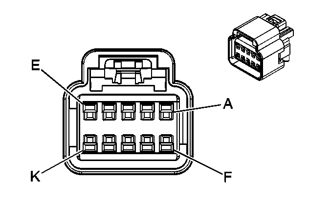
|
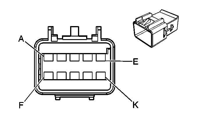
| ||||||||||||||
|---|---|---|---|---|---|---|---|---|---|---|---|---|---|---|---|
Connector Part Information |
| Connector Part Information |
| ||||||||||||
Pin | Wire Color | Circuit No. | Function | Pin | Wire Color | Circuit No. | Function | ||||||||
A | OG | 1340 | Battery Positive Voltage | A | OG | 1340 | Battery Positive Voltage | ||||||||
B | PU | 1807 | Class 2 Serial Data (UE1) | B | PU | 1807 | Class 2 Serial Data (UE1) | ||||||||
C | YE/BK | 693 | Cellular Telephone Mute Signal (UE1) | C | YE/BK | 693 | Cellular Telephone Mute Signal (UE1) | ||||||||
D | BARE | 814 | Drain Wire (UE1) | D | BARE | 814 | Drain Wire (UE1) | ||||||||
E | BN/WH | 367 | Remote Radio Left Audio Signal (U2K) | E | BN/WH | 367 | Remote Radio Left Audio Signal (U2K) | ||||||||
F | BK/WH | 372 | Remote Radio Audio Output (-) (U2K) | F | BK/WH | 372 | Remote Radio Audio Output (-) (U2K) | ||||||||
G | D-GN/WH | 368 | Remote Radio Right Audio Signal (U2K) | G | D-GN/WH | 368 | Remote Radio Right Audio Signal (U2K) | ||||||||
H | OG/BK | 2061 | Cellular Telephone Voice Low Reference (UE1) | H | OG/BK | 2061 | Cellular Telephone Voice Low Reference (UE1) | ||||||||
J | PK/BK | 2062 | Cellular Telephone Voice Signal (UE1) | J | PK/BK | 2062 | Cellular Telephone Voice Signal (UE1) | ||||||||
K | D-GN | 5060 | Low Speed GMLAN Serial Data (U2K) | K | D-GN | 5060 | Low Speed GMLAN Serial Data (U2K) | ||||||||
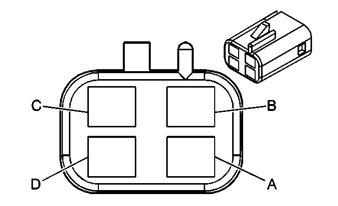
|
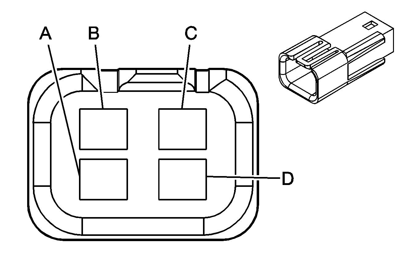
| ||||||||||||||
|---|---|---|---|---|---|---|---|---|---|---|---|---|---|---|---|
Connector Part Information |
| Connector Part Information |
| ||||||||||||
Pin | Wire Color | Circuit No. | Function | Pin | Wire Color | Circuit No. | Function | ||||||||
A | GY | 8 | Instrument Panel Lamp Supply Voltage - 1 | A | GY | 8 | Instrument Panel Lamp Supply Voltage - 1 | ||||||||
B | BN | 323 | Shift Lock Solenoid Supply Voltage | B | BN | 323 | Shift Lock Solenoid Supply Voltage | ||||||||
C | D-GN/WH | 1932 | Transmission Shift Select Switch (Park) Signal | C | D-GN/WH | 1932 | Transmission Shift Select Switch (Park) Signal | ||||||||
D | BK | 550 | Ground | D | BK | 550 | Ground | ||||||||
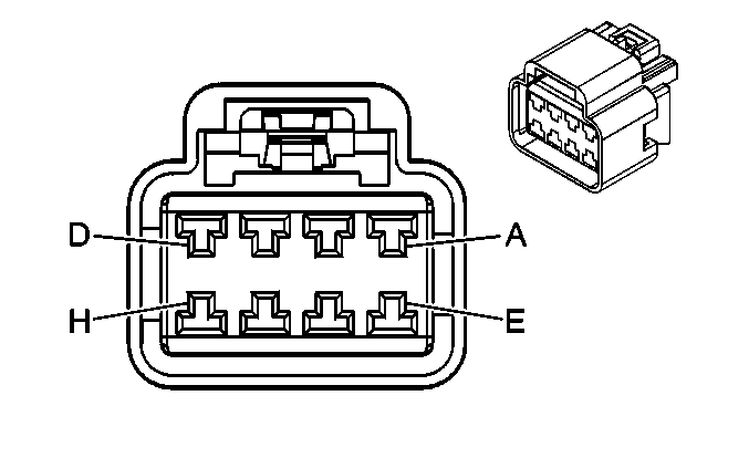
|
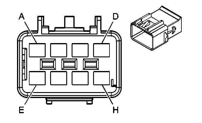
| ||||||||||||||
|---|---|---|---|---|---|---|---|---|---|---|---|---|---|---|---|
Connector Part Information |
| Connector Part Information |
| ||||||||||||
Pin | Wire Color | Circuit No. | Function | Pin | Wire Color | Circuit No. | Function | ||||||||
A | YE | 243 | Accessory Voltage | A | YE | 243 | Accessory Voltage | ||||||||
B | L-GN | 24 | Backup Lamp Supply Voltage | B | L-GN | 24 | Backup Lamp Supply Voltage | ||||||||
C | BK | 750 | Ground | C | BK | 750 | Ground | ||||||||
D | GY/BK | 1798 | Low Reference (DF5) | D | L-GN/BK | 1798 | Low Reference | ||||||||
E | L-GN/BK | 735 | Ambient Air Temperature Sensor Signal (DF5) | E | L-GN/BK | 735 | Ambient Air Temperature Sensor Signal | ||||||||
F | OG | 1732 | Inadvertent Power Supply Voltage | F | OG | 1732 | Inadvertent Power Supply Voltage | ||||||||
OG | 1732 | Inadvertent Power Supply Voltage | |||||||||||||
G | WH | 156 | Courtesy Lamp Low Control | G | WH | 156 | Courtesy Lamp Low Control | ||||||||
WH | 156 | Courtesy Lamp Low Control | |||||||||||||
H | L-BU | 20 | Stop Lamp Supply Voltage/Stop Lamp Switch Signal | H | L-BU | 20 | Stop Lamp Supply Voltage/Stop Lamp Switch Signal | ||||||||

|

| ||||||||||||||
|---|---|---|---|---|---|---|---|---|---|---|---|---|---|---|---|
Connector Part Information |
| Connector Part Information |
| ||||||||||||
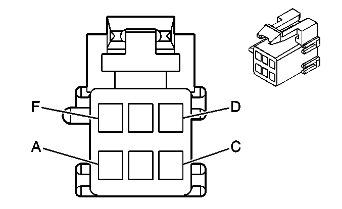
Pin | Wire Color | Circuit No. | Function | Pin | Wire Color | Circuit No. | Function | ||||||||
A | YE | 243 | Accessory Voltage | A | YE | 243 | Accessory Voltage | ||||||||
B | L-GN | 24 | Backup Lamp Supply Voltage | B | L-GN | 24 | Backup Lamp Supply Voltage | ||||||||
C | BK | 750 | Ground | C | BK | 750 | Ground | ||||||||
D | GY/BK | 1798 | Low Reference (2.2L) | D | L-GN/BK | 1798 | Low Reference (DF5) | ||||||||
E | L-GN/BK | 735 | Ambient Air Temperature Sensor Signal (2.2L) | E | L-GN/BK | 735 | Ambient Air Temperature Sensor Signal (DF5) | ||||||||
F | OG | 1732 | Inadvertent Power Supply Voltage | F | OG | 1732 | Inadvertent Power Supply Voltage | ||||||||
OG | 1732 | Inadvertent Power Supply Voltage (2.0L) | OG | 1732 | Inadvertent Power Supply Voltage | ||||||||||
G | WH | 156 | Courtesy Lamp Low Control | G | WH | 156 | Courtesy Lamp Low Control | ||||||||
WH | 156 | Courtesy Lamp Low Control | |||||||||||||
H | L-BU | 20 | Stop Lamp Supply Voltage/Stop Lamp Switch Signal | H | L-BU | 20 | Stop Lamp Supply Voltage/Stop Lamp Switch Signal | ||||||||
|
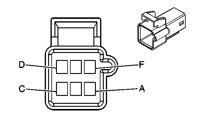
| ||||||||||||||
|---|---|---|---|---|---|---|---|---|---|---|---|---|---|---|---|
Connector Part Information |
| Connector Part Information |
| ||||||||||||
Pin | Wire Color | Circuit No. | Function | Pin | Wire Color | Circuit No. | Function | ||||||||
A | BN/WH | 2517 | Keypad Red LED Signal | A | BN/WH | 2517 | Keypad Red LED Signal | ||||||||
B | YE/BK | 2516 | Keypad Green LED Signal | B | YE/BK | 2516 | Keypad Green LED Signal | ||||||||
C | D-GN/WH | 2514 | Keypad Signal | C | D-GN/WH | 2514 | Keypad Signal | ||||||||
D | L-GN/BK | 2515 | Keypad Supply Voltage | D | L-GN/BK | 2515 | Keypad Supply Voltage | ||||||||
E | BARE | 654 | Cellular Telephone Microphone Low Reference | E | BARE | 654 | Cellular Telephone Microphone Low Reference | ||||||||
F | GY | 655 | Cellular Microphone Signal | F | GY | 655 | Cellular Microphone Signal | ||||||||

| |||||||||||||||
|---|---|---|---|---|---|---|---|---|---|---|---|---|---|---|---|
Connector Part Information |
| Connector Part Information |
| ||||||||||||
Pin | Wire Color | Circuit No. | Function | Pin | Wire Color | Circuit No. | Function | ||||||||
A | BK | 850 | Ground | A | BK | 850 | Ground | ||||||||
B | D-GN | 146 | Trunk Ajar Indicator Control (AU0) | B | OG/BK | 737 | Rear Compartment Lamp Control (W/O AUO) | ||||||||
D-GN | 146 | Trunk Ajar Indicator Control (AU0) | |||||||||||||
C | BN | 9 | Park Lamp Supply Voltage | C | BN | 9 | Park Lamp Supply Voltage | ||||||||
D | BK/WH | 56 | Trunk Release Motor Control | D | BK/WH | 56 | Trunk Release Motor Control | ||||||||
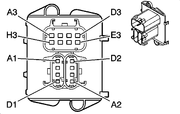
|
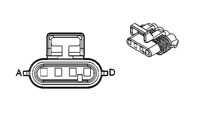
| ||||||||||||||||
|---|---|---|---|---|---|---|---|---|---|---|---|---|---|---|---|---|---|
Connector Part Information |
| Connector Part Information |
| ||||||||||||||
Pin | Wire Color | Circuit No. | Function | Pin | Wire Color | Circuit No. | Function | ||||||||||
A1 | PK | 439 | Ignition 1 Voltage (2.2L) | A | PK | 439 | Ignition 1 Voltage (2.2L) | ||||||||||
OG | 840 | Battery Positive Voltage (2.0L) | OG | 840 | Battery Positive Voltage (2.0L) | ||||||||||||
B1 | WH | 1310 | EVAP Canister Vent Solenoid Control | B | WH | 1310 | EVAP Canister Vent Solenoid Control | ||||||||||
C1-D1 | -- | -- | Not Used | C-D | -- | -- | Not Used | ||||||||||

|
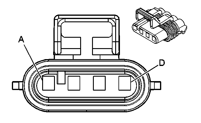
| ||||||||||||||
|---|---|---|---|---|---|---|---|---|---|---|---|---|---|---|---|
Connector Part Information |
| Connector Part Information |
| ||||||||||||
Pin | Wire Color | Circuit No. | Function | Pin | Wire Color | Circuit No. | Function | ||||||||
A2 | WH | 883 | Right Rear Wheel Speed Sensor Low Reference | A | WH | 883 | Right Rear Wheel Speed Sensor Low Reference | ||||||||
B2 | BN | 882 | Right Rear Wheel Speed Sensor Signal | B | BN | 882 | Right Rear Wheel Speed Sensor Signal | ||||||||
C2 | RD | 885 | Left Rear Wheel Speed Sensor Low Reference | C | RD | 885 | Left Rear Wheel Speed Sensor Low Reference | ||||||||
D2 | BK | 884 | Left Rear Wheel Speed Sensor Signal | D | BK | 884 | Left Rear Wheel Speed Sensor Signal | ||||||||

|
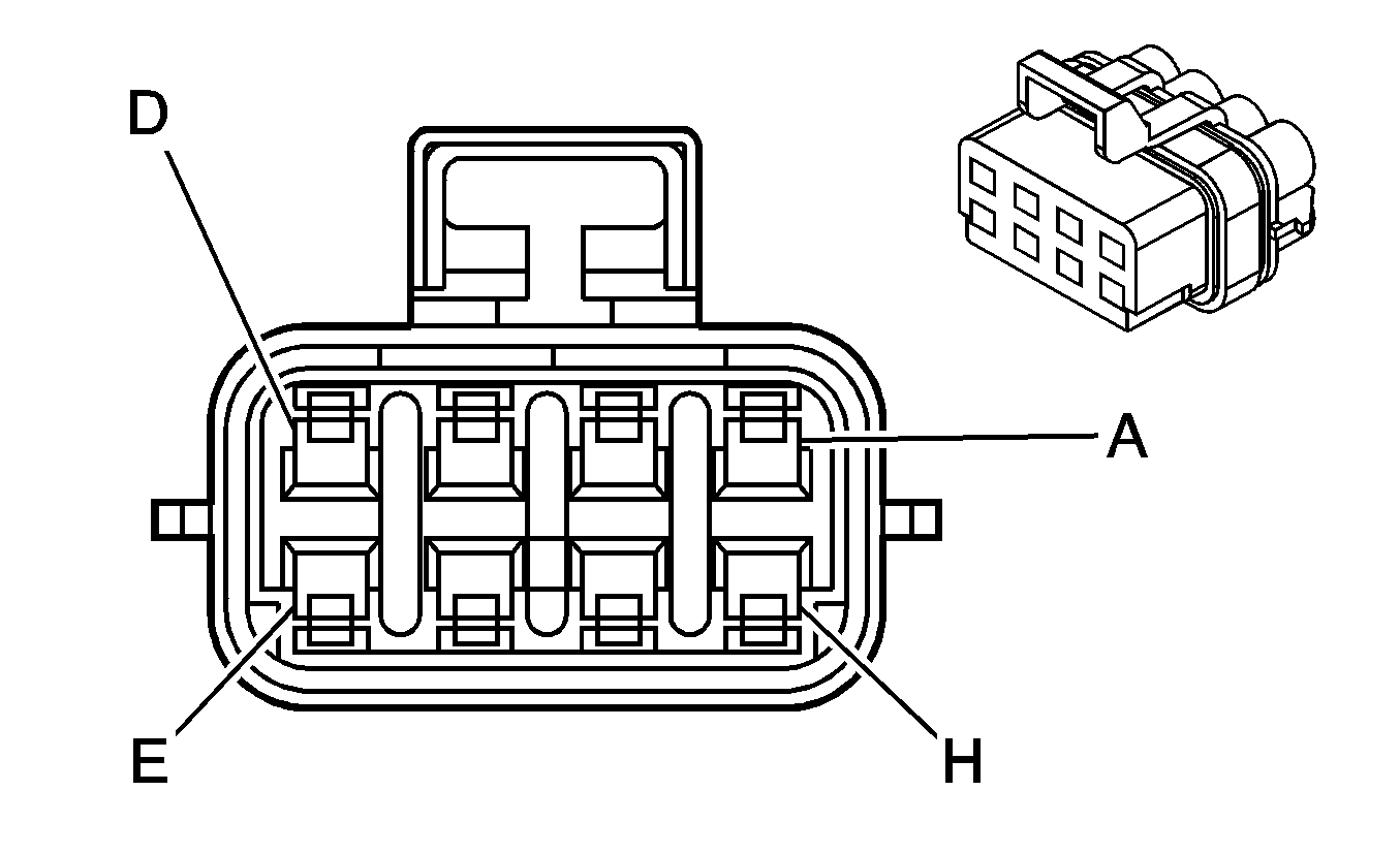
| ||||||||||||||||
|---|---|---|---|---|---|---|---|---|---|---|---|---|---|---|---|---|---|
Connector Part Information |
| Connector Part Information |
| ||||||||||||||
Pin | Wire Color | Circuit No. | Function | Pin | Wire Color | Circuit No. | Function | ||||||||||
A3 | BK | 650 | Ground | A | BK | 650 | Ground | ||||||||||
B3 | BK | 2759 | Low Reference | B | PK/OG | 2759 | Low Reference | ||||||||||
BK | 2759 | Low Reference | |||||||||||||||
C3 | GY | 120 | Fuel Pump Supply Voltage | C | PK/BK | 120 | Fuel Pump Supply Voltage | ||||||||||
D3 | PU | 1589 | Fuel Level Sensor Signal | D | YE/WH | 1589 | Fuel Level Sensor Signal | ||||||||||
E3 | -- | -- | Not Used | E | -- | -- | Not Available | ||||||||||
F3 | GY | 705 | 5-Volt Reference | F | BN/WH | 416 | 5-Volt Reference | ||||||||||
G3 | D-GN | 890 | Fuel Tank Pressure Sensor Signal | G | GY/RD | 890 | Fuel Tank Pressure Sensor Signal | ||||||||||
H3 | BK | 2759 | Low Reference | H | RD/PK | 2759 | Low Reference | ||||||||||

|

| ||||||||||||||
|---|---|---|---|---|---|---|---|---|---|---|---|---|---|---|---|
Connector Part Information |
| Connector Part Information |
| ||||||||||||
Pin | Wire Color | Circuit No. | Function | Pin | Wire Color | Circuit No. | Function | ||||||||
A | D-GN | 19 | Right Rear Stop/Turn Lamp Supply Voltage | A | YE | 19 | Right Rear Stop/Turn Lamp Supply Voltage | ||||||||
B | L-BU | 20 | Stop Lamp Switch Signal | B | L-BU | 20 | Stop Lamp Switch Signal | ||||||||
C | BN | 9 | Park Lamp Supply Voltage | C | BN | 9 | Park Lamp Supply Voltage | ||||||||
D | L-GN | 24 | Backup Lamp Supply Voltage | D | L-GN | 24 | Backup Lamp Supply Voltage | ||||||||
E | BK | 850 | Ground | E | BK | 850 | Ground | ||||||||
F | -- | -- | Not Used | F | -- | -- | Not Used | ||||||||

|

| ||||||||||||||
|---|---|---|---|---|---|---|---|---|---|---|---|---|---|---|---|
Connector Part Information |
| Connector Part Information |
| ||||||||||||
Pin | Wire Color | Circuit No. | Function | Pin | Wire Color | Circuit No. | Function | ||||||||
A | YE | 18 | Left Rear Stop/Turn Lamp Supply Voltage | A | YE | 18 | Left Rear Stop/Turn Lamp Supply Voltage | ||||||||
B | L-BU | 20 | Stop Lamp Switch Signal | B | L-BU | 20 | Stop Lamp Switch Signal | ||||||||
C | BN | 9 | Park Lamp Supply Voltage | C | BN | 9 | Park Lamp Supply Voltage | ||||||||
D | L-GN | 24 | Backup Lamp Supply Voltage | D | L-GN | 24 | Backup Lamp Supply Voltage | ||||||||
E | BK | 750 | Ground | E | BK | 750 | Ground | ||||||||
F | -- | -- | Not Used | F | -- | -- | Not Used | ||||||||

|

| ||||||||||||||
|---|---|---|---|---|---|---|---|---|---|---|---|---|---|---|---|
Connector Part Information |
| Connector Part Information |
| ||||||||||||
Pin | Wire Color | Circuit No. | Function | Pin | Wire Color | Circuit No. | Function | ||||||||
A | D-BU | 1857 | Left Front Speaker Output (-) | A | D-BU | 1857 | Left Front Speaker Output (-) | ||||||||
B | L-BU | 1957 | Left Front Speaker Output (+) | B | L-BU | 1957 | Left Front Speaker Output (+) | ||||||||
C | WH | 682 | Door Lock/Unlock Signal (AU3) | C | WH | 682 | Door Lock/Unlock Signal (AU3) | ||||||||
D | BK | 650 | Ground (AU3) | D | BK | 650 | Ground (AU3 w/D35) | ||||||||
PU/WH | 889 | Passenger Mirror Motor Down Control (Sedan w/DG7) | PU/WH | 889 | Passenger Mirror Motor Down Control (Sedan w/DG7) | ||||||||||
E | TN | 694 | Driver Door Lock Actuator Unlock Control | E | TN | 694 | Driver Door Lock Actuator Unlock Control | ||||||||
F | GY | 295 | Door Lock Actuator Unlock Control | F | GY | 295 | Door Lock Actuator Lock Control | ||||||||
G | RD/WH | 881 | Passenger Mirror Motor Right Control (Sedan w/DG7) | G | RD/WH | 881 | Passenger Mirror Motor Right Control (Sedan w/DG7) | ||||||||
WH | 2132 | Side Impact Sensing Module - Left - Signal (Coupe w/ASF) | WH | 2132 | Side Impact Sensing Module - Left - Signal (Coupe w/ASF) | ||||||||||
H | GY | 90 | Passenger Mirror Motor Up/Right (Sedan w/DG7) | H | GY | 90 | Passenger Mirror Motor Up/Right (Sedan w/DG7) | ||||||||
YE | 2131 | Side Impact Sensing Module - Left - Voltage (Coupe w/ASF) | YE | 2131 | Side Impact Sensing Module - Left - Voltage (Coupe w/ASF) | ||||||||||
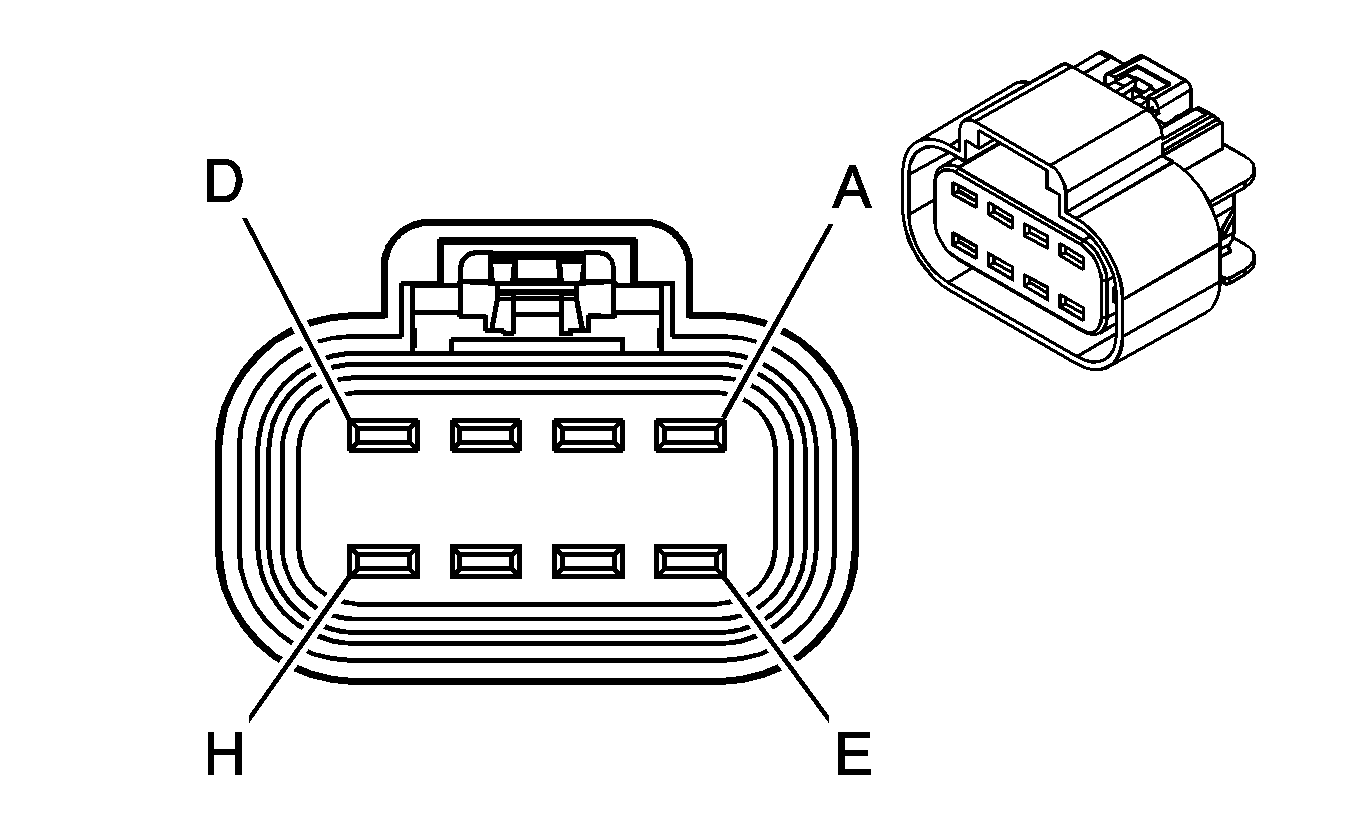
|
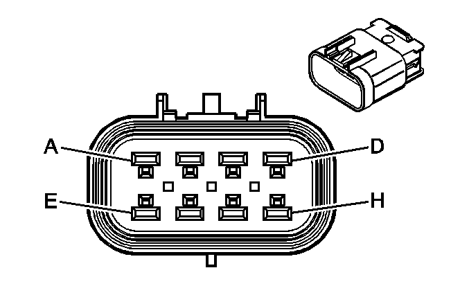
| ||||||||||||||
|---|---|---|---|---|---|---|---|---|---|---|---|---|---|---|---|
Connector Part Information |
| Connector Part Information |
| ||||||||||||
Pin | Wire Color | Circuit No. | Function | Pin | Wire Color | Circuit No. | Function | ||||||||
A | OG | 1732 | Courtesy Lamps Supply Voltage (DG7) | A | OG | 1732 | Courtesy Lamps Supply Voltage (DG7) | ||||||||
B | RD/WH | 881 | Passenger Mirror Motor Right Control (DG7) | B | RD/WH | 881 | Passenger Mirror Motor Right Control (DG7) | ||||||||
C | PU/WH | 889 | Passenger Mirror Motor Down Control (DG7) | C | PU/WH | 889 | Passenger Mirror Motor Down Control (DG7) | ||||||||
D | GY | 90 | Passenger Mirror Motor Left Control (DG7) | D | GY | 90 | Passenger Mirror Motor Left Control (DG7) | ||||||||
E | BN | 441 | Ignition 3 Voltage (A31) | E | BN | 441 | Ignition 3 Voltage (A31) | ||||||||
F | L-BU | 166 | Power Window Master Switch Right Front Up Signal (A31) | F | L-BU | 166 | Power Window Master Switch Right Front Up Signal (A31) | ||||||||
G | TN | 167 | Power Window Master Switch Right Front Down Signal (A31) | G | TN | 167 | Power Window Master Switch Right Front Down Signal (A31) | ||||||||
H | BK | 650 | Ground | H | BK | 650 | Ground | ||||||||
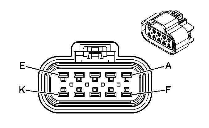
|
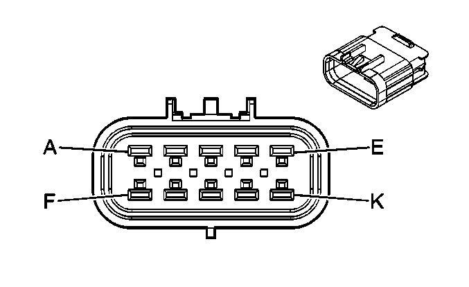
| ||||||||||||||
|---|---|---|---|---|---|---|---|---|---|---|---|---|---|---|---|
Connector Part Information |
| Connector Part Information |
| ||||||||||||
Pin | Wire Color | Circuit No. | Function | Pin | Wire Color | Circuit No. | Function | ||||||||
A | BN | 441 | Ignition 3 Voltage (A31) | A | BN | 441 | Ignition 3 Voltage (A31) | ||||||||
B | L-BU | 166 | Power Window Master Switch Right Front Up Signal (A31) | B | L-BU | 166 | Power Window Master Switch Right Front Up Signal (A31) | ||||||||
C | TN | 167 | Power Window Master Switch Right Front Down Signal (A31) | C | TN | 167 | Power Window Master Switch Right Front Down Signal (A31) | ||||||||
D | D-GN | 168 | Power Window Master Switch Left Rear Up Signal (A31) | D | D-GN | 168 | Power Window Master Switch Left Rear Up Signal (A31) | ||||||||
E | PU | 169 | Power Window Master Switch Left Rear Down Signal (A31) | E | PU | 169 | Power Window Master Switch Left Rear Down Signal (A31) | ||||||||
F | L-GN | 170 | Power Window Master Switch Right Rear Up Signal (A31) | F | L-GN | 170 | Power Window Master Switch Right Rear Up Signal (A31) | ||||||||
G | PU | 171 | Power Window Master Switch Right Rear Down Signal (A31) | G | PU | 171 | Power Window Master Switch Right Rear Down Signal (A31) | ||||||||
H | BK | 650 | Ground | H | BK | 650 | Ground | ||||||||
J | OG | 1732 | Inadvertent Power Supply Voltage (DG7) | J | OG | 1732 | Inadvertent Power Supply Voltage (DG7) | ||||||||
K | D-BU | 1307 | Power Window Master Switch Lockout Signal (A31) | K | D-BU | 1307 | Power Window Master Switch Lockout Signal (A31) | ||||||||

|

| ||||||||||||||
|---|---|---|---|---|---|---|---|---|---|---|---|---|---|---|---|
Connector Part Information |
| Connector Part Information |
| ||||||||||||
Pin | Wire Color | Circuit No. | Function | Pin | Wire Color | Circuit No. | Function | ||||||||
A | D-BU | 1857 | Left Front Speaker Output (-) | A | D-BU | 1857 | Left Front Speaker Output (-) | ||||||||
B | L-BU | 1957 | Left Front Speaker Output (+) | B | L-BU | 1957 | Left Front Speaker Output (+) | ||||||||

|

| ||||||||||||||
|---|---|---|---|---|---|---|---|---|---|---|---|---|---|---|---|
Connector Part Information |
| Connector Part Information |
| ||||||||||||
Pin | Wire Color | Circuit No. | Function | Pin | Wire Color | Circuit No. | Function | ||||||||
A | D-GN | 117 | Right Front Speaker Output (-) (U79/UX7) | A | D-GN | 117 | Right Front Speaker Output (-) (U79/UX7) | ||||||||
OR | 1853 | Right Front Speaker Output (-) (UZ6) | OR | 1853 | Right Front Speaker Output (-) (UZ6) | ||||||||||
B | L-GN | 200 | Right Front Speaker Output (+) (U79/UX7) | B | L-GN | 200 | Right Front Speaker Output (+) (U79/UX7) | ||||||||
D-GN | 1953 | Right Front Speaker Output (+) (UZ6) | D-GN | 1953 | Right Front Midrange Speaker Output (+) (UZ6) | ||||||||||
C | WH | 682 | Door Lock/Unlock Signal | C | WH | 682 | Door Lock/Unlock Signal | ||||||||
D | BK | 650 | Ground | D | BK | 650 | Ground | ||||||||
E | TN | 294 | Door Lock Actuator Unlock Control | E | TN | 294 | Door Lock Actuator Unlock Control | ||||||||
F | GY | 295 | Door Lock Actuator Lock Control | F | GY | 295 | Door Lock Actuator Lock Control | ||||||||
G | D-GN | 2134 | Side Impact Sensing Module - Right - Signal | G | D-GN | 2134 | Side Impact Sensing Module - Right - Signal | ||||||||
H | TN | 2133 | Side Impact Sensing Module - Right - Voltage | H | TN | 2133 | Side Impact Sensing Module - Right - Voltage | ||||||||

|

| ||||||||||||||
|---|---|---|---|---|---|---|---|---|---|---|---|---|---|---|---|
Connector Part Information |
| Connector Part Information |
| ||||||||||||
Pin | Wire Color | Circuit No. | Function | Pin | Wire Color | Circuit No. | Function | ||||||||
A | -- | -- | Not Used | A | -- | -- | Not Used | ||||||||
B | RD/WH | 881 | Passenger Mirror Motor Right Control | B | RD/WH | 881 | Passenger Mirror Motor Right Control | ||||||||
C | PU/WH | 889 | Passenger Mirror Motor Down Control | C | PU/WH | 889 | Passenger Mirror Motor Down Control | ||||||||
D | GY | 90 | Passenger Mirror Motor Left Control | D | GY | 90 | Passenger Mirror Motor Left Control | ||||||||
E | BN | 441 | Ignition 3 Voltage | E | BN | 441 | Ignition 3 Voltage | ||||||||
F | L-BU | 166 | Power Window Master Switch Right Front Up Signal | F | L-BU | 166 | Power Window Master Switch Right Front Up Signal | ||||||||
G | TN | 167 | Power Window Master Switch Right Front Down Signal | G | TN | 167 | Power Window Master Switch Right Front Down Signal | ||||||||
H | -- | -- | Not Used | H | -- | -- | Not Used | ||||||||

|

| ||||||||||||||
|---|---|---|---|---|---|---|---|---|---|---|---|---|---|---|---|
Connector Part Information |
| Connector Part Information |
| ||||||||||||
Pin | Wire Color | Circuit No. | Function | Pin | Wire Color | Circuit No. | Function | ||||||||
A | D-GN | 117 | Right Front Speaker Output (-) | A | D-GN | 117 | Right Front Speaker Output (-) | ||||||||
B | L-GN | 200 | Right Front Speaker Output (+) | B | L-GN | 200 | Right Front Speaker Output (+) | ||||||||
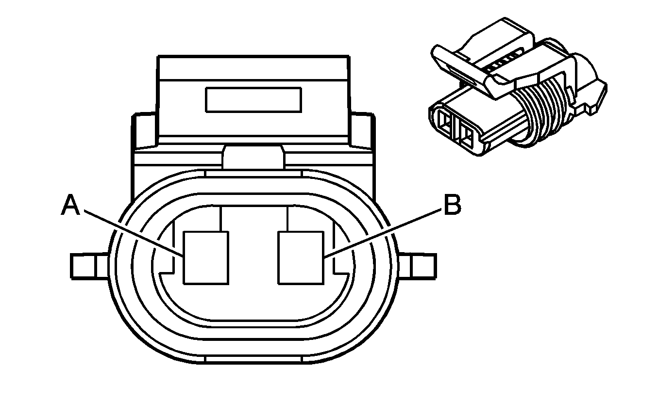
|
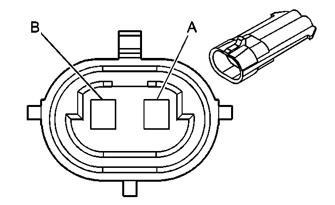
| ||||||||||||||
|---|---|---|---|---|---|---|---|---|---|---|---|---|---|---|---|
Connector Part Information |
| Connector Part Information |
| ||||||||||||
Pin | Wire Color | Circuit No. | Function | Pin | Wire Color | Circuit No. | Function | ||||||||
A | GY | 295 | Door Lock Actuator Lock Control | A | GY | 295 | Door Lock Actuator Lock Control | ||||||||
B | TN | 294 | Door Lock Actuator Unlock Control | B | TN | 294 | Door Lock Actuator Unlock Control | ||||||||

|

| ||||||||||||||
|---|---|---|---|---|---|---|---|---|---|---|---|---|---|---|---|
Connector Part Information |
| Connector Part Information |
| ||||||||||||
Pin | Wire Color | Circuit No. | Function | Pin | Wire Color | Circuit No. | Function | ||||||||
A | GY | 295 | Door Lock Actuator Lock Control | A | GY | 295 | Door Lock Actuator Lock Control | ||||||||
B | TN | 294 | Door Lock Actuator Unlock Control | B | TN | 294 | Door Lock Actuator Unlock Control | ||||||||
