Tools Required
| • | J 45341
Rear Wheel Drive Shaft Removal Tool |
Removal Procedure
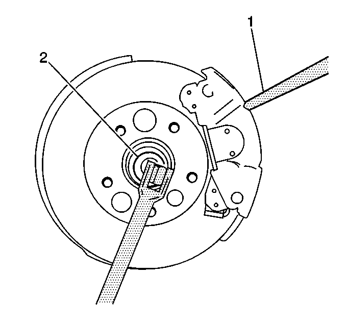
- Raise and support the vehicle. Refer to
Lifting and Jacking the Vehicle
.
- Remove the tire and wheel assembly. Refer to
Tire and Wheel Removal and Installation
.
- Insert a brass drift or punch (1) in the brake rotor and rest it against the brace caliper mounting bracket.
- Using a socket and breaker bar (2), remove the wheel drive shaft retaining nut.
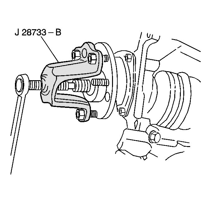
- Install the
J 28733-B
, 7208A Hub Remover - OTC, CJ129 Universal Hub
Puller - Snap-On, 7394 Universal Hub Puller - OTC, or equivalent, to the wheel bearing/hub assembly and secure with lug nuts.
Important: Ensure the wheel speed sensor wiring harness is repositioned away from the ball joint after disconnecting the electrical connector from the sensor.
- Disconnect the ball joint from the steering knuckle. Refer to
Lower Control Arm Replacement
.
- Separate the wheel drive shaft from the wheel bearing/hub assembly, then support the shaft assembly.
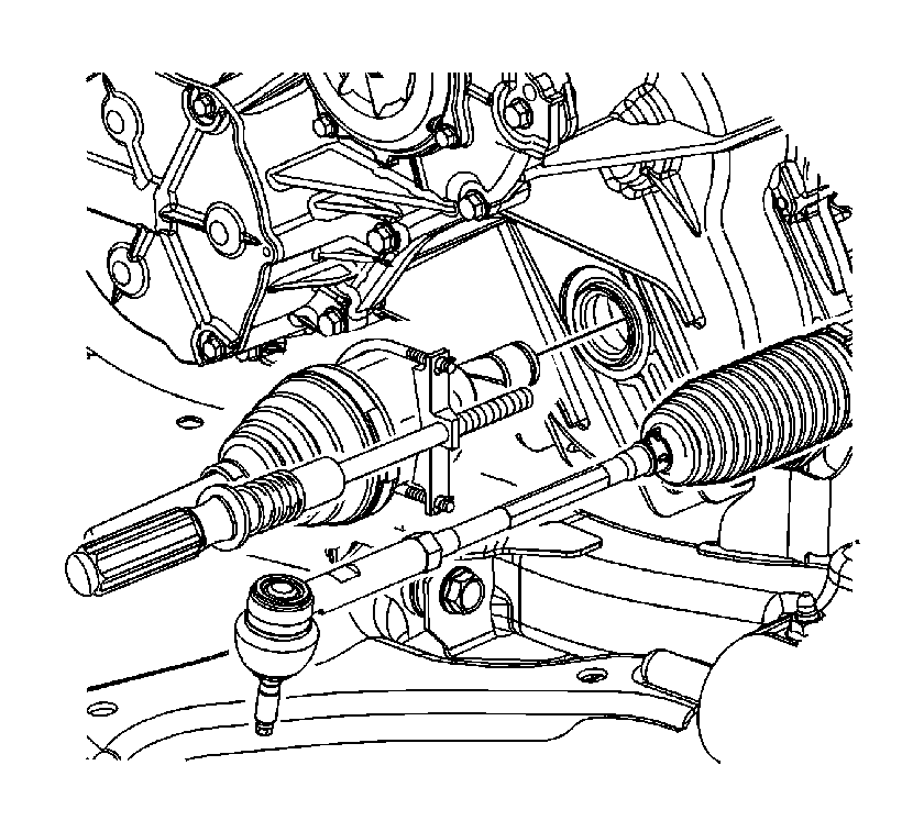
- Assemble the
J 45341
and the
J-2619-A
to the
wheel drive shaft inner tripot housing assembly.
Important: The transmission stub staff may still could be attached to the right wheel drive shaft and be removed at the same time as the wheel drive shaft. If this occurs, refer to
Stub Shaft Removal
.
- Using the
J 45341
and the
J-2619-A
, separate the wheel drive shaft from the transaxle, then remove the shaft assembly.
- Inspect the transaxle output shaft seal for damage and/or contamination and replace if necessary. Refer to
Right Hand Axle Seal Removal
for the 4T45-E transmission or
Front Wheel Drive Shaft Seal Replacement
for the M86 Getrag transmission.
Installation Procedure
- Install the
J 44394
into the transaxle output shaft seal.
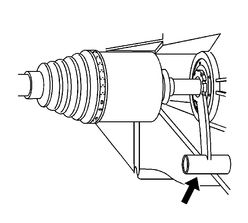
- Install the wheel drive shaft into the transaxle until the drive shaft splines are past the seal, remove the
J 44394
, then fully install the drive shaft.
- Verify that the wheel drive shaft is properly engaged:
| • | Grasp the inner tripod housing and pull the inner housing outward. Do NOT pull on the wheel drive axle shaft. |
| • | The wheel drive shaft will remain firmly in place when properly engaged. |
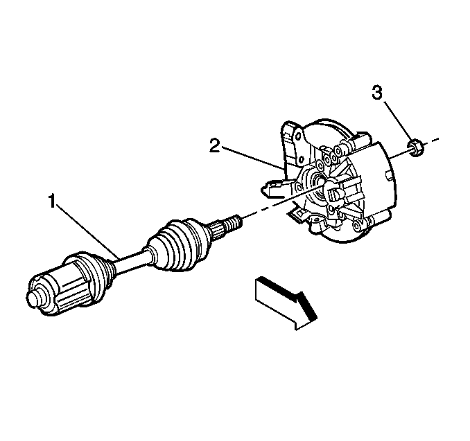
- Install the wheel drive shaft (1) to the wheel bearing/hub assembly.
- Connect the ball joint to the steering knuckle. Refer to
Lower Control Arm Replacement
.
Notice: Refer to Fastener Notice in the Preface section.
- Install the wheel drive shaft nut (3) to the wheel drive shaft assembly (1).
Tighten
Tighten the nut to 100 N·m (74 lb ft) plus 35°.
- Install the tire and wheel assembly. Refer to
Tire and Wheel Removal and Installation
.
- Lower the vehicle.
- Inspect the transaxle fluid level.


