Customer Satisfaction - Camshaft Position Sensor Housing Seal Replacement

| Subject: | CAMSHAFT POSITION SENSOR HOUSING SEAL REPLACEMENT |
| Models: | 2004-2005 ION Red Line Vehicles with Supercharged 2.0L 4-Cylinder (LSJ) Engines |
| Attention: | All Saturn Retailers and Authorized Service Providers in the United States |
Important: Saturn Retailers in Canada: The Canadian version of this bulletin follows the U.S. version.
Saturn has learned that certain 2004 and 2005 model year Saturn ION Red Line vehicles equipped with supercharged 2.0L 4-cylinder (LSJ) engines have a condition where the camshaft position sensor housing seal may fail prematurely, resulting in an engine oil leak. Engine damage could occur if the oil level is significantly low.
To correct this condition, Saturn retailers will install a new camshaft position sensor housing seal that has been re-designed to improve seal life. This service will be performed at no cost to the owner.
Vehicles Involved
Certain 2004 and 2005 model year Saturn ION Red Line vehicles within the following VIN range will require participation in this program.
4Z100063 - 5Z139240
You must verify program involvement through your AS400 system. It is important to note that program claims will only be paid on involved vehicles.
Owner Notification
Owners of all involved vehicles will be notified of this customer satisfaction program by Saturn. (Refer to the owner letter included in this bulletin.)
Facility VIN Listing
A list of vehicles assigned to you (Facility VIN Listing), which our records indicate were sold by or shipped to you, (or are located in close proximity to your facility) is enclosed. This listing contains:
| • | Complete vehicle identification number (VIN); and |
| • | VINs of vehicles, which according to Saturn records are in retail stock. |
The Facility VIN Listing is furnished to involved Retailers with the customer satisfaction program bulletin.
Those Retailers not involved initially in this program will receive a message at the top of a blank Facility VIN Listing that states: NO VEHICLES ASSIGNED AT THIS TIME.
Retailer Responsibility
All unsold vehicles in Retailers’ possession and subject to this recall must be held and inspected/repaired per the service procedure of this program bulletin before owners take possession of these vehicles.
Retailers are to service all vehicles subject to this program at no charge to owners, regardless of mileage, age of vehicle, or ownership, from this time forward.
Owners who have recently purchased vehicles sold from your vehicle inventory, and for which there is no customer information indicated on the retailer listing, are to be contacted by the retailer. Arrangements are to be made to make the required correction according to the procedure contained in this bulletin. This could be done by mailing to such customers, a copy of the customer letter accompanying this bulletin. Recall follow-up cards should not be used for this purpose, since the customer may not have received the notification letter.
In summary, whenever a vehicle subject to this program enters your vehicle inventory, or is in your retail facility for service in the future, you must take the steps necessary to be sure the program correction has been made before selling or releasing the vehicle.
Customer Reimbursement
All customer requests for reimbursement for previous repairs for the customer satisfaction program condition will be handled by the Customer Assistance Center or Saturn retailer.
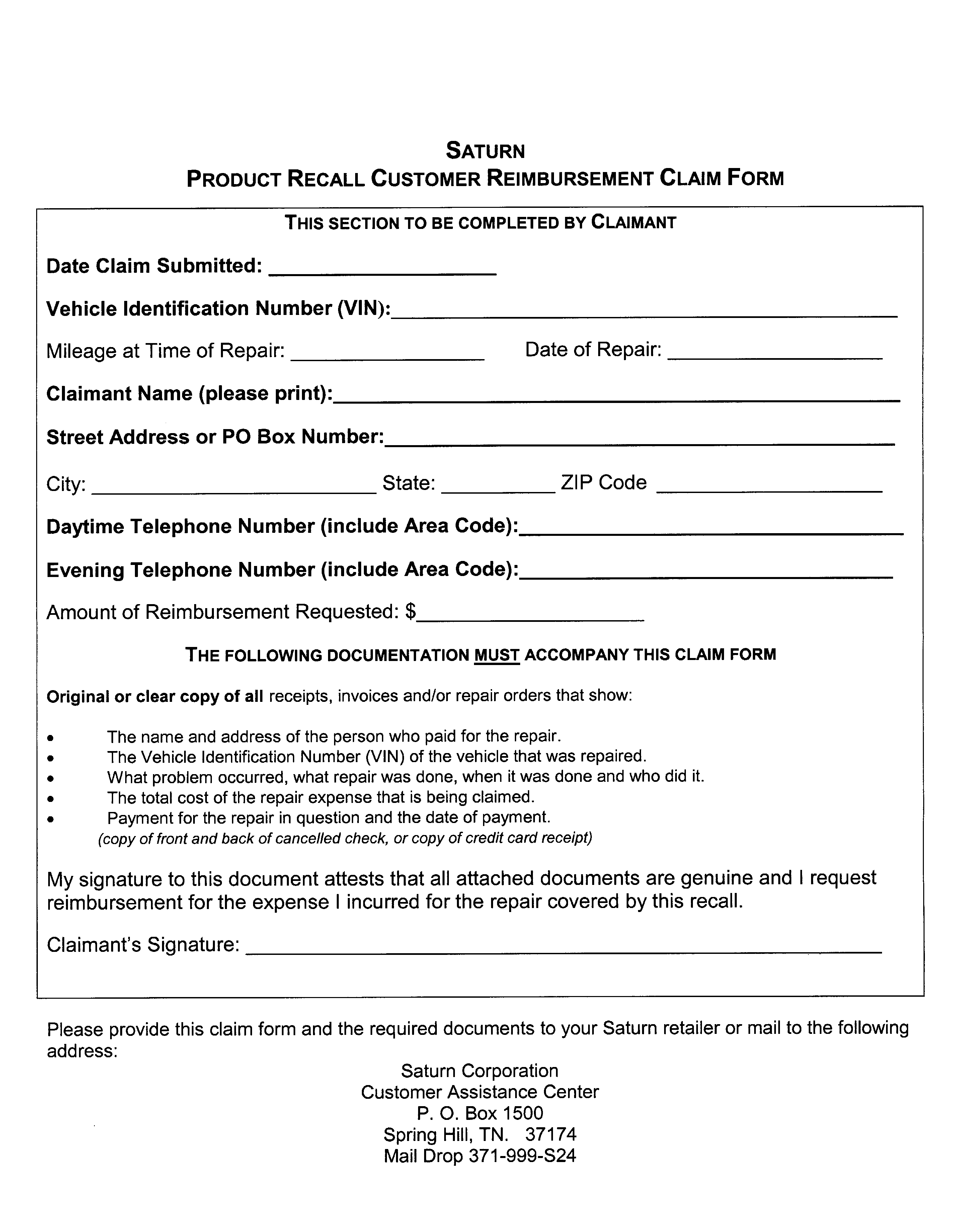
A Saturn Product Recall Customer Reimbursement Procedure Form will be included with the customer letter.
Transfer of Customer Satisfaction Program Responsibility
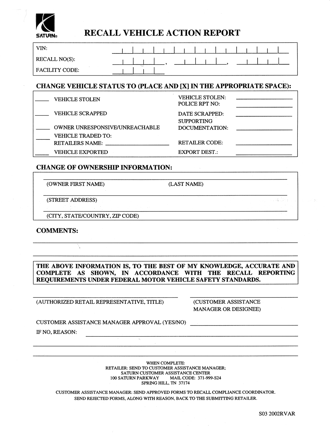
Saturn vehicles that have been sold to you, which may be closer in proximity to another Saturn Retailer, may still appear on your Facility VIN Listing. If you determine that it is more desirable for a vehicle on your Facility VIN Listing to be serviced by another Saturn Retailer, responsibility may be transferred by completing a Recall Vehicle Action Report and submitting it to your Customer Assistance Manager (CAM) at the Saturn Customer Assistance Center.
A copy of the Recall Vehicle Action Report is included for your reference. Additional copies can be ordered from Saturn Publications (win.wallace.com/Saturn or 1-800-828-2112, prompt 3, Item # S03 2002 RVAR). All changes to program responsibility will be reflected in your next Unfixed VIN Report.
All other changes in vehicle status (e.g., scrapped, stolen, etc.) are to be made in accordance with section 4.4.3 of the Retailer Service Reference Guide, "Notifying Saturn of Vehicle Status Change."
Parts Information
- A pre-shipment of the required parts to perform this program has been automatically sent to involved Retailers from Saturn Service Parts Operations (SSPO). These initial shipments are to aid Retailers in program preparation and ensure minimal customer inconvenience.
- Should you require any additional parts, please contact your Parts Support Analyst (PSA) to expedite parts shipment.
Part Number | Description | Qty/ Vehicle |
|---|---|---|
12597644 | SEAL - CM/SHF POSN SEN HSG OIL (O-RING) (Camshaft Position Sensor Housing Seal) | 1 |
U.S.A 12378521 Canada 88901148 | ThreeBond 1217F® Sealant | $2.07 per vehicle* Billed as Net Item "M" |
Important: All material prices are retailer cost plus 40%.
* One tube will service 12 vehicles. One tube $24.81/12 vehicles = $2.07 per vehicle.
Total Material Allowance is $2.07 per vehicle.
Disposition of Replaced Parts
Retailers will scrap all replaced parts in a manner that ensures that they cannot be reused, remanufactured, or otherwise entered into the stream of commerce in the future.
Suggestions for Ensuring Customer Satisfaction
As you know, Saturn’s success hinges upon our ability to execute superior customer support throughout the ownership experience, especially when important corrective actions such as this are required.
It is imperative that every effort is made to accommodate the affected owners. Additionally, priority should be given to customer vehicles over retail inventory vehicles. If you have any questions, please coordinate with the Saturn Customer Assistance Center to help ensure customer satisfaction.
Service Procedure
- Record vehicle preset radio stations.
- Turn OFF all the lamps and the accessories.
- Make sure the ignition switch is in the OFF position.
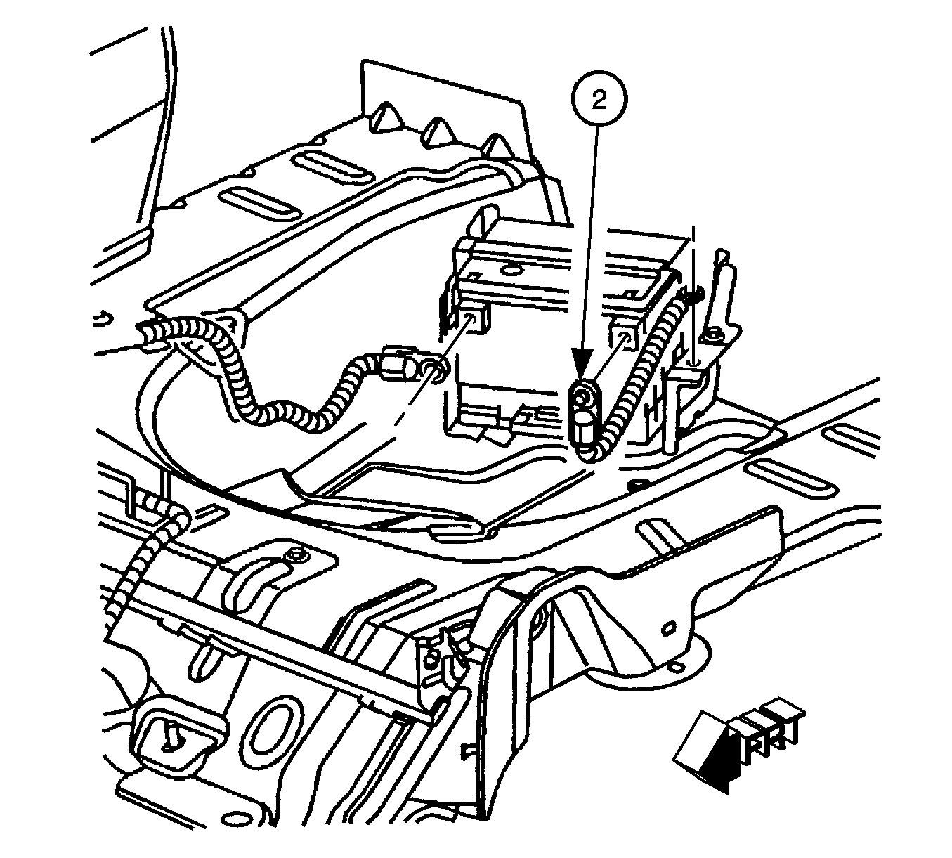
- Disconnect negative battery cable (2).
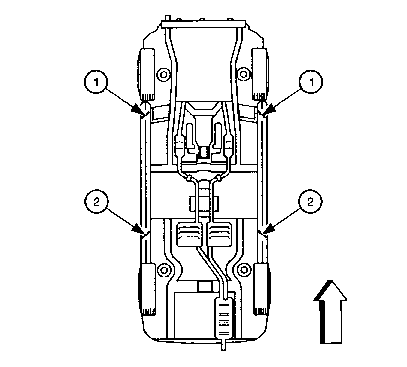
- Raise vehicle on hoist until the tires are off the ground. Place front lift pads (1 in illustration) 170 mm (6.69 in) from front pinchweld flanges, rear lift pads (2) 55 mm (2.17 in) from rear pinchweld flanges.
- Remove right front tire.
- Remove inner right side splash shield to gain access to crankshaft pulley.
- Remove ignition coil/spark plug cover.
- Remove cylinder #4 ignition coil and spark plug.
- Install spark plug adapter 309729 from SA9127E Universal Pressure Test Kit in #4 cylinder spark plug hole.
- Hang gauge bar 53476 from "D-Ring" on the hood and align the gauge so that you can see it from the right front tire area of the vehicle. Attach pressure hose 309734 to the "Pressure Oil, Fuel, Cylinder Leak" port of the gauge bar and spark plug adapter.
- Rotate the engine to bring the cylinder #4 to top dead center (TDC) compression stroke. The crankshaft pulley-timing notch should be aligned with the timing mark on the front cover.
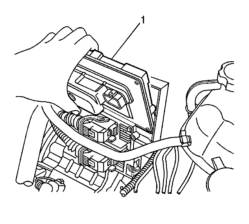
- Remove powertrain control module (PCM) from mounting bracket. Do NOT disconnect any electrical connectors. Use the retaining tab to release the PCM from the underhood junction block bracket.
- Perform underhood electrical center removal procedure.
- Remove the two fasteners holding the clutch master cylinder to the front of dash to allow easier access to the camshaft position sensor housing.
- Remove the brake booster vacuum hose from the supercharger and set it aside.
- Remove the two fasteners (studs) holding the camshaft position sensor housing assembly to the cylinder head.
- Slide the camshaft position sensor housing assembly back away from the cylinder head.
- Remove and discard green camshaft position sensor housing seal.
- Using a shop towel, wipe clean the "cog" (hex shaft) of the camshaft position trigger and the mating surfaces of the camshaft position sensor housing assembly and the cylinder head.
- Place two 6 mm (0.236 in) - 10 mm (0.393 in) dots of ThreeBond 1217F® sealant, P/N 12378521, on the cylinder head as shown in illustration.
- Install the NEW camshaft position sensor housing seal, P/N 12597644. The new seal is black.
- Align the timing mark on the "cog" (hex shaft) to the timing mark on the camshaft position sensor housing.
- Install the camshaft position sensor housing assembly to the cylinder head.
- Install the camshaft position sensor housing studs.
- Install brake booster vacuum hose to supercharger.
- Install the two fasteners to the clutch master cylinder.
- Perform underhood electrical center installation procedure.
- Install PCM. Secure PCM to underhood junction block bracket with retaining tab.
- Install the right front inner splash shield.
- Install the right front tire. Tighten nuts in a "star" pattern.
- Lower vehicle.
- Remove spark plug adapter, house and gauge bar.
- Install cylinder #4 ignition coil and spark plug.
- Install ignition coil/spark plug cover retaining bolts.
- Connect the battery negative cable to the battery (2).
- Reset the radio stations and the clock.
- Check oil level and adjust if necessary.
Caution: Before servicing any electrical component, the ignition key must be in the OFF or LOCK position and all electrical loads must be OFF, unless instructed otherwise in these procedures. If a tool or equipment could easily come in contact with a live exposed electrical terminal, also disconnect the negative battery cable. Failure to follow these precautions may cause personal injury and/or damage to the vehicle or its components.
Caution: To avoid any vehicle damage, serious personal injury or death when major components are removed from the vehicle and the vehicle is supported by a hoist, support the vehicle with jack stands at the opposite end from which the components are being removed.
Caution: To avoid any vehicle damage, serious personal injury or death, always use the jackstands to support the vehicle when lifting the vehicle with a jack.
Notice: Perform the following steps before beginning any vehicle lifting or jacking procedure:
• Remove or secure all of the vehicle's contents in order to avoid any shifting or any movement that may occur during the vehicle lifting or jacking procedure. • The lifting or jacking equipment weight rating must meet or exceed the weight of the vehicle and any vehicle contents. • The lifting or jacking equipment must meet the operational standards of the lifting or jacking equipment's manufacturer. • Perform vehicle lifting or jacking procedure on a clean, hard, dry, level surface. • Perform the vehicle lifting or jacking procedure only at the identified lift points. DO NOT allow the lifting equipment or jacking equipment to contact any other vehicle components.
Important: Place jackstands ONLY under strong and stable vehicle structures.
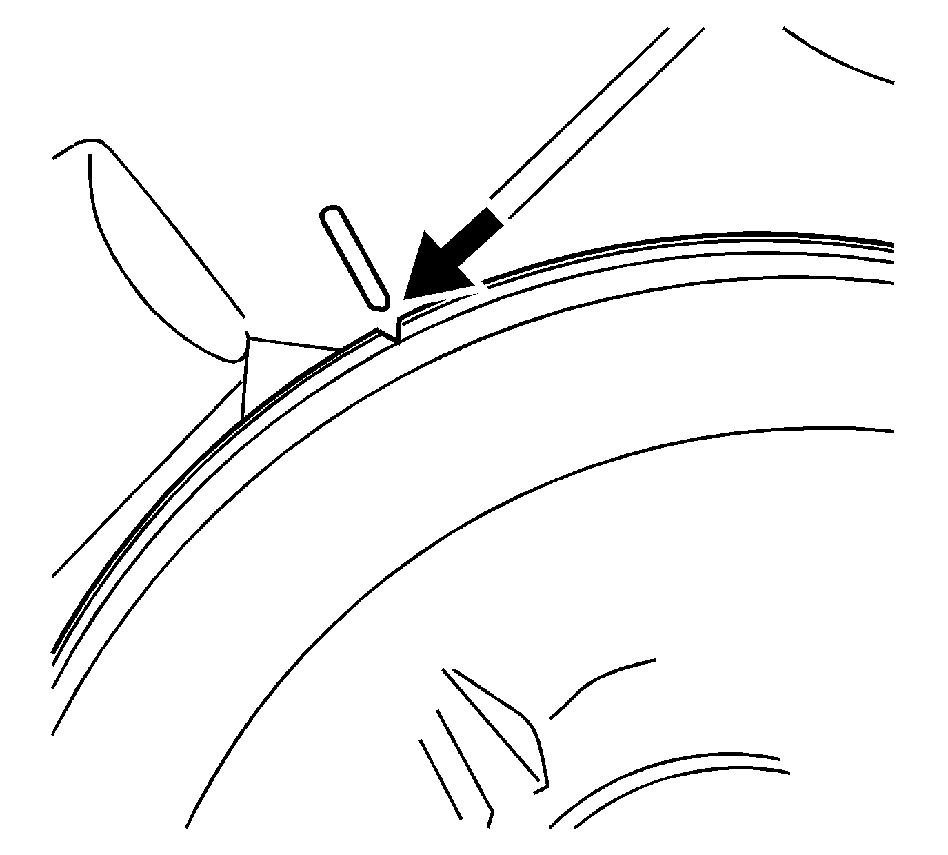
Important: To determine #4 cylinder top dead center (TDC) compression stroke, rotate the engine by the crankshaft pulley and watch the pressure gauge on the gauge bar. When pressure begins to build use an inspection mirror and continue to rotate the crankshaft pulley until the timing marks are aligned as shown in the illustration.
| 14.1. | Remove the cover from the underhood electrical center. |
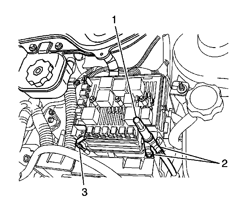
| 14.2. | Remove the underhood positive battery terminal lug (1). |
| Important: Take note of the positioning of the positive battery cables before disconnecting the cables. |
| 14.3. | Disconnect the positive battery cables (2) from the underhood electrical center. |
| 14.4. | Remove the electric power steering (EPS) cable nut from the underhood electrical center. |
| 14.5. | Disconnect the EPS cable (3) from the underhood electrical center. |
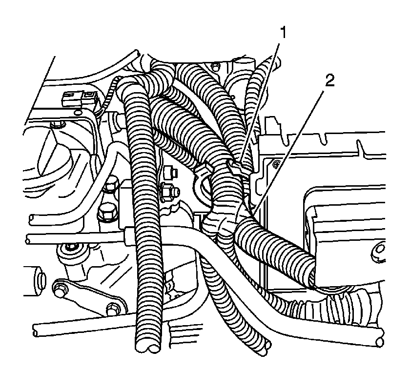
| 14.6. | Release the engine wiring harness retainer (1), next to the powertrain control module (PCM). Reposition the wiring harness (2) toward the engine. |
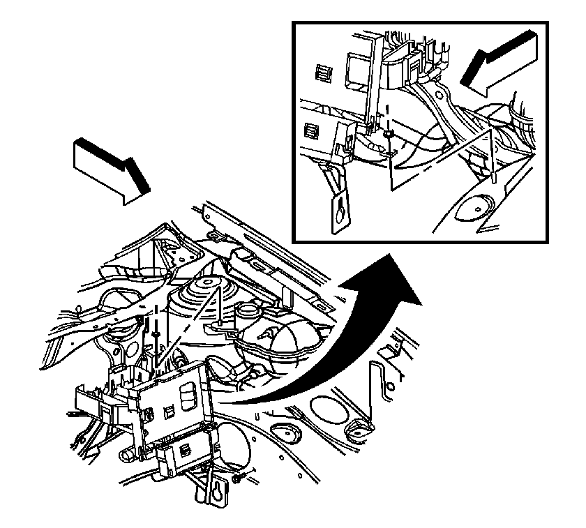
| 14.7. | Release the EPS cable retainer from the underhood electrical center bracket. |
| 14.8. | Release the forward lamp harness retainer from the outboard side of the PCM tray. |
| 14.9. | Release the surge tank inlet hose clip from the electrical center bracket. |
| 14.10. | Remove the cooling system surge tank mounting nut. |
| 14.11. | Remove the underhood electrical center bracket mounting nut. |
| 14.12. | Remove the electrical center bracket mounting bolt. |
| 14.13. | Lift the bracket off of the studs and reposition the bracket slightly toward the engine. |
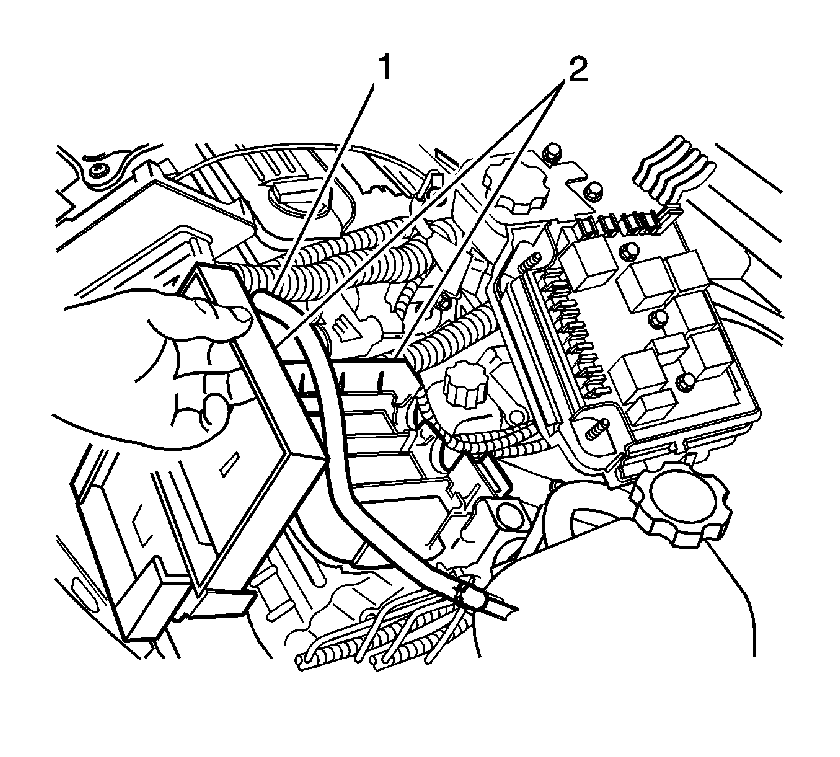
| 14.14. | Lift the surge tank hose (1) slightly and move the electrical center and electrical center bracket (2) toward the front of the vehicle. |
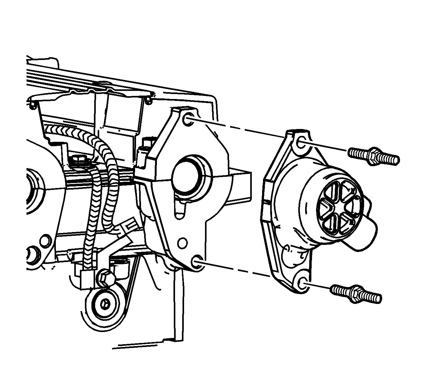
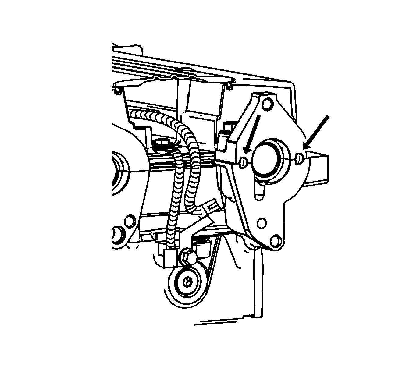
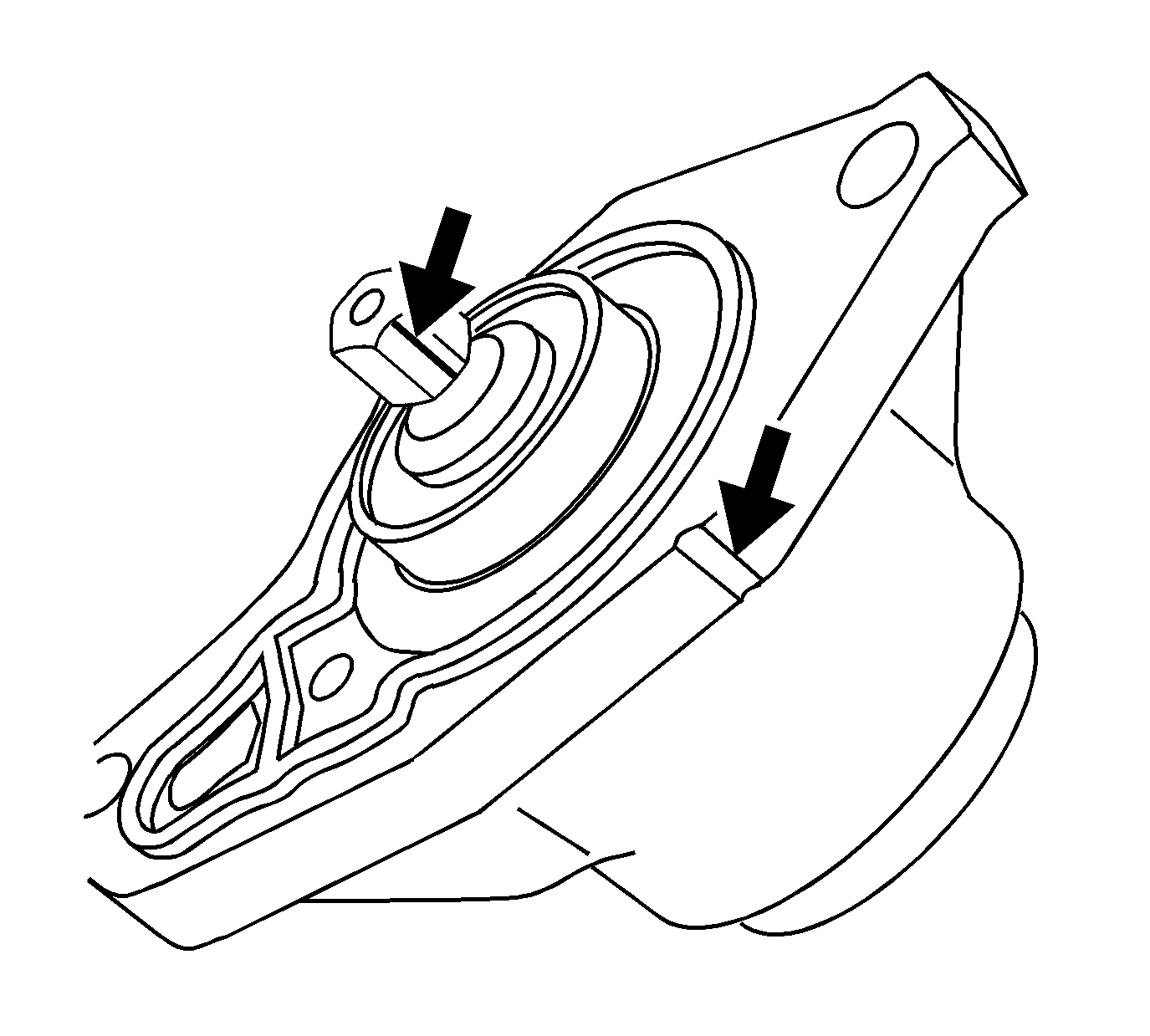

Notice: Use the correct fastener in the correct location. Replacement fasteners must be the correct part number for that application. Fasteners requiring replacement or fasteners requiring the use of thread locking compound or sealant are identified in the service procedure. Do not use paints, lubricants, or corrosion inhibitors on fasteners or fastener joint surfaces unless specified. These coatings affect fastener torque and joint clamping force and may damage the fastener. Use the correct tightening sequence and specifications when installing fasteners in order to avoid damage to parts and systems.
Tighten
Tighten the camshaft position sensor housing studs to 22 N·m (16 lb-ft).
Tighten
Tighten fasteners to 10 N·m (89 lb-in).

| 28.1. | Position the electrical center bracket (2) to the vehicle. |
| 28.2. | Lift the surge tank inlet hose (1) slightly and move the electrical center bracket (2) toward the rear of the vehicle, just inboard of the installed position. |

| 28.3. | Position the electrical center bracket onto the studs at the surge tank and on the frame rail. |
| 28.4. | Install the underhood electrical center bracket mounting bolt. Do not tighten yet. |
| 28.5. | Install the underhood electrical center bracket mounting nut. |
Tighten
Tighten the bracket mounting nut to 10 N·m (89 lb-in).
| 28.6. | Install the cooling system surge tank mounting nut. |
Tighten
Tighten the surge tank mounting nut to 10 N·m (89 lb-in).
| 28.7. | Tighten the underhood electrical center bracket mounting bolt. |
Tighten
Tighten bracket mounting bolt to 25 N·m (18 lb-ft).
| 28.8. | Secure the forward lamp harness retainer to the outboard side of the PCM tray. |
| 28.9. | Secure the EPS cable retainer to the underhood electrical center bracket. |

| 28.10. | Install the engine wiring harness (2) to the retainer (1), next to the PCM. Secure the harness retainer (1). |

| 28.11. | Connect the EPS cable (3) to the underhood electrical center. |
| 28.12. | Install the electric power steering (EPS) cable nut. |
Tighten
Tighten the EPS cable nut to 10 N·m (89 lb-in).
| 28.13. | Connect the positive battery cables (2) to the underhood electrical center. Position the cables as noted previously. |
| 28.14. | Install the underhood positive battery terminal lug (1). |
Tighten
Tighten the battery lug to 15 N·m (11 lb-ft).
| 28.15. | Install the cover to the underhood electrical center. |

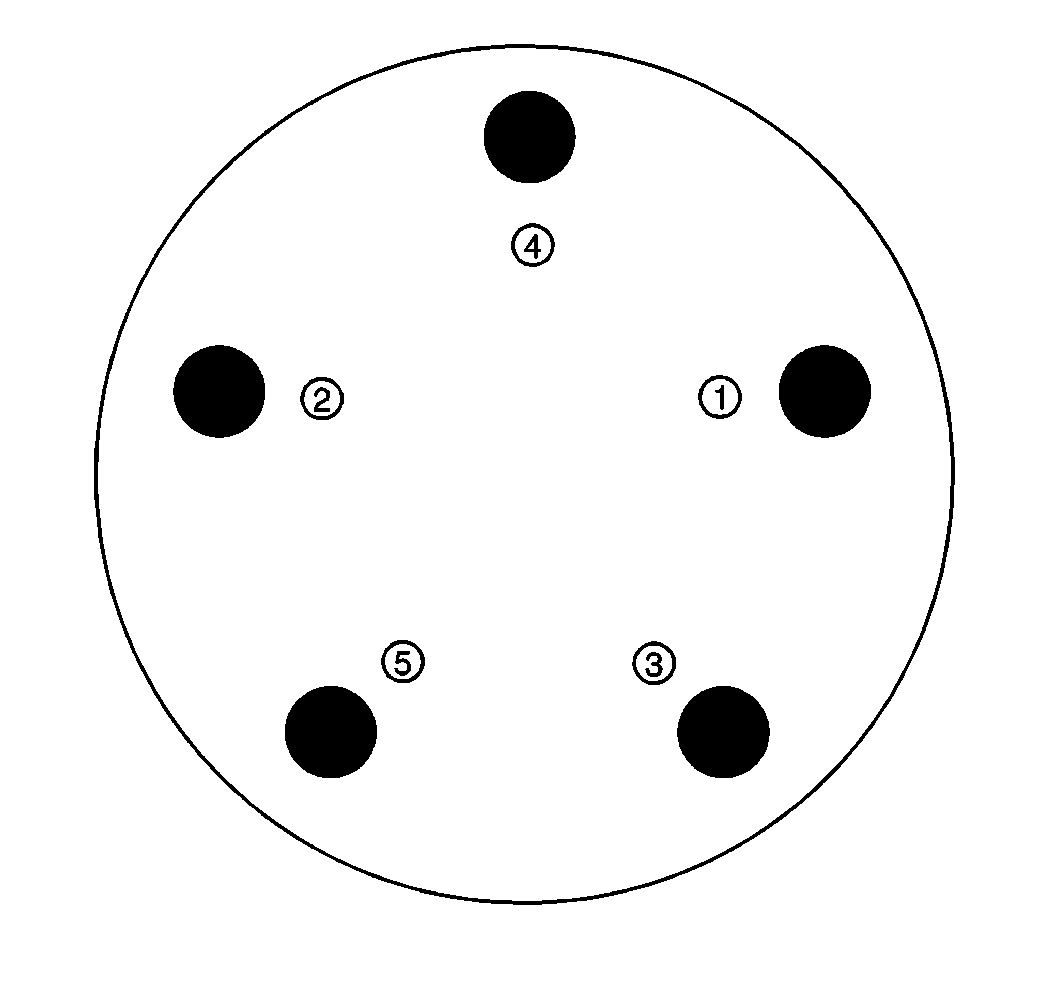
Tighten
Tighten wheel nuts 140 N·m (100 lb-ft)
Important: Make sure that the ignition coil seals are properly seated to the valve cover.
Tighten
Tighten spark plug to 20 N·m (15 lb-ft). Tighten ignition coil retaining bolts to 10 N·m (89 lb-in).
Tighten
Tighten ignition coil/spark plug cover retaining bolts to 8 N·m (71 lb-in).

Tighten
Tighten cable bolt to 17 N·m (13 lb-ft).
Important: If engine exhibits an extended crank of over 3 seconds, the camshaft position sensor housing may not be timed properly. Verify the position of the camshaft sensor housing and adjust if necessary using the procedures outlined in this bulletin. Start engine to verify there are no leaks and the camshaft position sensor housing is timed properly.
Claim Information
1. To receive credit, submit a claim with the information below:
Repair Performed | Parts Allow | Sale Type | Case Type | Labor Op | Labor Hours* | Admin. Hrs.**** |
|---|---|---|---|---|---|---|
Seal, Camshaft Position Sensor Housing Oil - Replace | * | WC | VC | V1322 | 1.0 | 0.1 |
* The parts allowance should be the sum total of the current SSPO Retailer net price plus 40% of all parts required for the repair. **** Administrative allowance. | ||||||
Claiming ThreeBond 1217F® Material
It will be necessary to sell these materials to the CSO as "material" using net item code "M" per the chart on page 4 of this bulletin. Claims received in the amount of $2.07 will be accepted. Claims exceeding the amount of $2.07 will be returned with Return Reason 143 - material/reimbursement > maximum allowed.
2. To receive credit for loaner/rental vehicle costs incurred while owner awaits program repair, submit a claim with the information below:
Repair Performed | Sale Type | Case Type | Labor Op | Net Item Amount | Net Item Code | # Days Rental |
|---|---|---|---|---|---|---|
Loaner/Rental Reimbursement | WC | VC | V1323 | ** | C | *** |
Customer Reimbursement | WC | VC | V1324 | **** | R | N/A |
** Net amount must be submitted as a miscellaneous sale...Loaner/rental reimbursement not to exceed $35/day. *** Enter number of days vehicle was rented...Not to exceed 1 day. The completed Loaner/Rental Worksheet must be attached to the hard copy of the Customer Service Order (CSO). **** Customer requests for reimbursement of previously paid repairs to replace Camshaft Position Sensor Housing Seal. | ||||||
3. Check your Saturn SERVICELINE.XL Claim Memorandum daily. Remember to code the claim as a WC sale type, and VC case type. Contact your field representative if you need assistance.
4. All labor operations claimed in this bulletin must be submitted on individual (unrelated) CSO lines. Refer to the Customer Service Order Preparation Manual for details on Bulletin Claim Submission.
5. Customer Reimbursement Claims - Special Attention Required
A. Customer reimbursement claims must have the date of the Camshaft Position Sensor Housing Seal prior replacement entered into the "repair date" field of the CSO in the "Labor Detail/Comments" screen.
B. Customer reimbursement claims must have the mileage of the prior repair of the Camshaft Position Sensor Housing Seal entered on the "Service Order Hub" screen in the "miles in" field.
C. Customer reimbursement claims must have entered into the "technician comments" field the CSO # (if repair was completed at a Saturn Retail Facility) date, mileage, customer name, and any deductibles and taxes paid by the customer.
D. Customer reimbursement claims must be submitted on a different CSO than the Recall repair. This is because the repair date and mileage differ between the two repairs.
Reimbursement
SATURN PRODUCT RECALL CUSTOMER REIMBURSEMENT PROCEDURE
If you paid to have this recall condition corrected prior to this notification, you may be eligible to receive reimbursement.
Requests for reimbursement may include parts, labor, fees and taxes. Reimbursement may be limited to the amount the repair would have cost if completed by an authorized Saturn retailer.
Submitting a recall reimbursement claim directly to your Saturn retailer may expedite processing; however, if you choose, you may file your claim through the Saturn Customer Assistance Center. Your claim will be acted upon within 60 days of receipt.
If your claim is:
| • | Approved, you will receive a check from your Saturn retailer or Saturn, |
| • | Denied, you will receive a letter from your Saturn retailer or Saturn with the reason(s) for the denial, or |
| • | Incomplete, you will receive a letter from your Saturn retailer or Saturn identifying the documentation that is needed to complete the claim and offered the opportunity to resubmit the claim when the missing documentation is available. |
Please follow the instructions on the Claim Form provided on the reverse side to file a claim for reimbursement. If you have any questions or need assistance, please contact your Saturn retailer or the Saturn Customer Assistance at 1-800-972-8876, or for the hearing impaired, 1-800-833-6000.
05522 Loaner/Rental Worksheet
Complete this worksheet and attach it to the hard copy of the Customer Service Order (CSO) to document all loaner/rental reimbursement claims submitted to Saturn.
VIN #____________________
A. Vehicle Loaner/Rental Allowance Explanation: $_________
_____________________________________________________
_____________________________________________________
_____________________________________________________
Repair Performed | Sale Type | Case Type | Labor Op | Net Item Code | # Days Rental |
|---|---|---|---|---|---|
Loaner/Rental Reimbursement | WC | VC | V1323 | C | * |
* Not to exceed $35/day. | |||||
B. Customer Requests Reimbursement
Explanation: (Attach original paid receipts/invoices verifying the repair, proof of payment, and proof of vehicle ownership at time of repair.) $___________
_____________________________________________________
_____________________________________________________
_____________________________________________________
Repair Performed | Sale Type | Case Type | Labor Op | Net Item Amount | Net Item Code | # Days Rental |
|---|---|---|---|---|---|---|
Customer Reimbursement | WC | VC | V1324 | ** | R | N/A |
** Customer requests for reimbursement of previously paid repairs to replace Camshaft Position Sensor Housing Seal. | ||||||
_______________________
Authorized Retailer Signature
05522 CAMSHAFT POSITION SENSOR HOUSING SEAL REPLACEMENT (CANADA)
Models: 2004-2005 ION Red Line Vehicles with Supercharged 2.0L 4-Cylinder (LSJ) Engines
Attention: General Motors of Canada Ltd. Saturn Retailers
Condition
Saturn has learned that certain 2004 and 2005 model year Saturn ION Red Line vehicles equipped with supercharged 2.0L 4-cylinder (LSJ) engines have a condition where the camshaft position sensor housing seal may fail prematurely, resulting in an engine oil leak. Engine damage could occur if the oil level is significantly low.
Correction
To correct this condition, Saturn retailers will install a new camshaft position sensor housing seal that has been re-designed to improve seal life.
Vehicles Involved
Involved are certain 2004 and 2005 model year Saturn ION Red Line vehicles built within these VIN breakpoints:
YEAR | DIVISION | MODEL | FROM | THROUGH |
|---|---|---|---|---|
2004 | SATURN | ION RED LINE | 4Z100063 | EOP |
2005 | SATURN | ION RED LINE | SOP | 5Z139240 |
Important: Retailers should confirm vehicle eligibility through GMVIS (GM Vehicle Inquiry System) before beginning recall repairs. [Not all vehicles within the above breakpoints may be involved.]
For retailers with involved vehicles, a Campaign Initiation Detail Report containing the complete Vehicle Identification Number, customer name and address data has been prepared, and is being furnished to involved retailers. Retailers that have no involved vehicles currently assigned, will not receive a Campaign Initiation Detail Report.
The Campaign Initiation Detail Report may contain customer names and addresses obtained from Motor Vehicle Registration Records. The use of such motor vehicle registration data for any purpose other than follow-up necessary to complete this recall is a violation of law in several states/provinces/countries. Accordingly, you are urged to limit the use of this report to the follow-up necessary to complete this recall.
Parts Information
Parts required to complete this recall are to be obtained from General Motors Service Parts Operations (GMSPO). Please refer to your "involved vehicles listing" before ordering parts. Normal orders should be placed on a DRO = Daily Replenishment Order. In an emergency situation, parts should be ordered on a CSO = Customer Special Order.
Part Number | Description | Qty/ Vehicle |
|---|---|---|
12597644 | SEAL - CM/SHF POSN SEN HSG OIL (O-RING) (Camshaft Position Sensor Housing Seal) | 1 |
Canada 88901148* | ThreeBond 1217F® Sealant | 1 per 12 vehicles |
* One tube will service 12 vehicles. One tube $21.87/12 vehicles = $1.83 per vehicle.
Total Material Allowance is $1.83 per vehicle.
Service Procedure
- Record vehicle preset radio stations.
- Turn OFF all the lamps and the accessories.
- Make sure the ignition switch is in the OFF position.
- Disconnect negative battery cable (2).
- Raise vehicle on hoist until the tires are off the ground. Place front lift pads (1 in illustration) 170 mm (6.69 in) from front pinchweld flanges, rear lift pads (2) 55 mm (2.17 in) from rear pinchweld flanges.
- Remove right front tire.
- Remove inner right side splash shield to gain access to crankshaft pulley.
- Remove ignition coil/spark plug cover.
- Remove cylinder #4 ignition coil and spark plug.
- Install spark plug adapter 309729 from SA9127E Universal Pressure Test Kit in #4 cylinder spark plug hole.
- Hang gauge bar 53476 from "D-Ring" on the hood and align the gauge so that you can see it from the right front tire area of the vehicle. Attach pressure hose 309734 to the "Pressure Oil, Fuel, Cylinder Leak" port of the gauge bar and spark plug adapter.
- Rotate the engine to bring the cylinder #4 to top dead centre (TDC) compression stroke. The crankshaft pulley-timing notch should be aligned with the timing mark on the front cover.
- Remove powertrain control module (PCM) from mounting bracket. Do NOT disconnect any electrical connectors. Use the retaining tab to release the PCM from the underhood junction block bracket.
- Perform underhood electrical centre removal procedure.
- Remove the two fasteners holding the clutch master cylinder to the front of dash to allow easier access to the camshaft position sensor housing.
- Remove the brake booster vacuum hose from the supercharger and set it aside.
- Remove the two fasteners (studs) holding the camshaft position sensor housing assembly to the cylinder head.
- Slide the camshaft position sensor housing assembly back away from the cylinder head.
- Remove and discard green camshaft position sensor housing seal.
- Using a shop towel, wipe clean the "cog" (hex shaft) of the camshaft position trigger and the mating surfaces of the camshaft position sensor housing assembly and the cylinder head.
- Place two 6 mm (0.236 in) - 10 mm (0.393 in) dots of ThreeBond 1217F® sealant, P/N 12378521, on the cylinder head as shown in illustration.
- Install the NEW camshaft position sensor housing seal, P/N 12597644. The new seal is black.
- Align the timing mark on the "cog" (hex shaft) to the timing mark on the camshaft position sensor housing.
- Install the camshaft position sensor housing assembly to the cylinder head.
- Install the camshaft position sensor housing studs.
- Install brake booster vacuum hose to supercharger.
- Install the two fasteners to the clutch master cylinder.
- Perform underhood electrical centre installation procedure.
- Install PCM. Secure PCM to underhood junction block bracket with retaining tab.
- Install the right front inner splash shield.
- Install the right front tire. Tighten nuts in a "star" pattern.
- Lower vehicle.
- Remove spark plug adapter, house and gauge bar.
- Install cylinder #4 ignition coil and spark plug.
- Install ignition coil/spark plug cover retaining bolts.
- Connect the battery negative cable to the battery (2).
- Reset the radio stations and the clock.
- Check oil level and adjust if necessary.
Caution: Before servicing any electrical component, the ignition key must be in the OFF or LOCK position and all electrical loads must be OFF, unless instructed otherwise in these procedures. If a tool or equipment could easily come in contact with a live exposed electrical terminal, also disconnect the negative battery cable. Failure to follow these precautions may cause personal injury and/or damage to the vehicle or its components.

Caution: To avoid any vehicle damage, serious personal injury or death when major components are removed from the vehicle and the vehicle is supported by a hoist, support the vehicle with jack stands at the opposite end from which the components are being removed.
Caution: To avoid any vehicle damage, serious personal injury or death, always use the jackstands to support the vehicle when lifting the vehicle with a jack.
Notice: Perform the following steps before beginning any vehicle lifting or jacking procedure:
• Remove or secure all of the vehicle's contents in order to avoid any shifting or any movement that may occur during the vehicle lifting or jacking procedure. • The lifting or jacking equipment weight rating must meet or exceed the weight of the vehicle and any vehicle contents. • The lifting or jacking equipment must meet the operational standards of the lifting or jacking equipment's manufacturer. • Perform vehicle lifting or jacking procedure on a clean, hard, dry, level surface. • Perform the vehicle lifting or jacking procedure only at the identified lift points. DO NOT allow the lifting equipment or jacking equipment to contact any other vehicle components.
Important: Place jackstands ONLY under strong and stable vehicle structures.


Important: To determine #4 cylinder top dead centre (TDC) compression stroke, rotate the engine by the crankshaft pulley and watch the pressure gauge on the gauge bar. When pressure begins to build use an inspection mirror and continue to rotate the crankshaft pulley until the timing marks are aligned as shown in the illustration.

| 14.1. | Remove the cover from the underhood electrical centre. |

| 14.2. | Remove the underhood positive battery terminal lug (1). |
| Important: Take note of the positioning of the positive battery cables before disconnecting the cables. |
| 14.3. | Disconnect the positive battery cables (2) from the underhood electrical centre. |
| 14.4. | Remove the electric power steering (EPS) cable nut from the underhood electrical centre. |
| 14.5. | Disconnect the EPS cable (3) from the underhood electrical centre. |

| 14.6. | Release the engine wiring harness retainer (1), next to the powertrain control module (PCM). Reposition the wiring harness (2) toward the engine. |

| 14.7. | Release the EPS cable retainer from the underhood electrical centre bracket. |
| 14.8. | Release the forward lamp harness retainer from the outboard side of the PCM tray. |
| 14.9. | Release the surge tank inlet hose clip from the electrical centre bracket. |
| 14.10. | Remove the cooling system surge tank mounting nut. |
| 14.11. | Remove the underhood electrical centre bracket mounting nut. |
| 14.12. | Remove the electrical centre bracket mounting bolt. |
| 14.13. | Lift the bracket off of the studs and reposition the bracket slightly toward the engine. |

| 14.14. | Lift the surge tank hose (1) slightly and move the electrical centre and electrical centre bracket (2) toward the front of the vehicle. |


Notice: Use the correct fastener in the correct location. Replacement fasteners must be the correct part number for that application. Fasteners requiring replacement or fasteners requiring the use of thread locking compound or sealant are identified in the service procedure. Do not use paints, lubricants, or corrosion inhibitors on fasteners or fastener joint surfaces unless specified. These coatings affect fastener torque and joint clamping force and may damage the fastener. Use the correct tightening sequence and specifications when installing fasteners in order to avoid damage to parts and systems.
Tighten
Tighten the camshaft position sensor housing studs to 22 N·m (16 lb-ft).
Tighten
Tighten fasteners to 10 N·m (89 lb-in).

| 28.1. | Position the electrical centre bracket (2) to the vehicle. |
| 28.2. | Lift the surge tank inlet hose (1) slightly and move the electrical centre bracket (2) toward the rear of the vehicle, just inboard of the installed position. |

| 28.3. | Position the electrical centre bracket onto the studs at the surge tank and on the frame rail. |
| 28.4. | Install the underhood electrical centre bracket mounting bolt. Do not tighten yet. |
| 28.5. | Install the underhood electrical centre bracket mounting nut. |
Tighten
Tighten the bracket mounting nut to 10 N·m (89 lb-in).
| 28.6. | Install the cooling system surge tank mounting nut. |
Tighten
Tighten the surge tank mounting nut to 10 N·m (89 lb-in).
| 28.7. | Tighten the underhood electrical centre bracket mounting bolt. |
Tighten
Tighten bracket mounting bolt to 25 N·m (18 lb-ft).
| 28.8. | Secure the forward lamp harness retainer to the outboard side of the PCM tray. |
| 28.9. | Secure the EPS cable retainer to the underhood electrical centre bracket. |

| 28.10. | Install the engine wiring harness (2) to the retainer (1), next to the PCM. Secure the harness retainer (1). |

| 28.11. | Connect the EPS cable (3) to the underhood electrical centre. |
| 28.12. | Install the electric power steering (EPS) cable nut. |
Tighten
Tighten the EPS cable nut to 10 N·m (89 lb-in).
| 28.13. | Connect the positive battery cables (2) to the underhood electrical centre. Position the cables as noted previously. |
| 28.14. | Install the underhood positive battery terminal lug (1). |
Tighten
Tighten the battery lug to 15 N·m (11 lb-ft).
| 28.15. | Install the cover to the underhood electrical centre. |


Tighten
Tighten wheel nuts 140 N·m (100 lb-ft)
Important: Make sure that the ignition coil seals are properly seated to the valve cover.
Tighten
Tighten spark plug to 20 N·m (15 lb-ft). Tighten ignition coil retaining bolts to 10 N·m (89 lb-in).
Tighten
Tighten ignition coil/spark plug cover retaining bolts to 8 N·m (71 lb-in).

Tighten
Tighten cable bolt to 17 N·m (13 lb-ft).
Important: If engine exhibits an extended crank of over 3 seconds, the camshaft position sensor housing may not be timed properly. Verify the position of the camshaft sensor housing and adjust if necessary using the procedures outlined in this bulletin. Start engine to verify there are no leaks and the camshaft position sensor housing is timed properly.
Claim Information
Submit a Product Recall Claim with the information indicated below:
REPAIR PERFORMED | PART COUNT | PART NO. | PARTS ALLOW | CC-FC | LABOUR OP | LABOUR HOURS | NET ITEM |
|---|---|---|---|---|---|---|---|
Seal, Camshaft Position Sensor Housing Oil - Replace | 1 | 12597644 | * | MA-96 | V1322 | 1.0 | ** |
* The "Parts Allowance" should be the sum total of the current GMSPO Retailer Net price plus applicable mark-up for the seal needed to complete the repair. ** One tube (part no. 88901148) will service 12 vehicles. One tube $21.87/12 vehicles = $1.83 per vehicle. Total Material Allowance is $1.83 per vehicle. | |||||||
Refer to the General Motors Claims Processing Manual for details on Product Recall Claim Submission.
Customer Notification
Customers will be notified of this recall on their vehicles by General Motors (see copy of customer letter included with this bulletin).
Retailer Recall Responsibility
All unsold new vehicles in Retailers' possession and subject to this recall must be held and inspected/repaired per the service procedure of this recall bulletin before customers take possession of these vehicles.
Retailers are to service all vehicles subject to this recall at no charge to customers, regardless of mileage, age of vehicle, or ownership, from this time forward.
Customers who have recently purchased vehicles sold from your vehicle inventory, and for which there is no customer information indicated on the Retailer listing, are to be contacted by the Retailer. Arrangements are to be made to make the required correction according to the instructions contained in this bulletin. This could be done by mailing to such customers a copy of the customer letter accompanying this bulletin. Recall follow-up cards should not be used for this purpose, since the customer may not as yet have received the notification letter.
In summary, whenever a vehicle subject to this recall enters your vehicle inventory, or is in your retail facility for service in the future, you must take the steps necessary to be sure the recall correction has been made before selling or releasing the vehicle.
March, 2005Dear Saturn Owner:
This notice is sent to inform you that Saturn is conducting a voluntary customer satisfaction program that affects 2004 and 2005 Saturn ION Red Line vehicles.
Saturn has learned that certain 2004 and 2005 model year Saturn ION Red Line vehicles equipped with supercharged 2.0L 4-cylinder (LSJ) engines have a condition where the camshaft position sensor housing seal may fail prematurely, resulting in an engine oil leak. Engine damage could occur if the oil level is significantly low.
What Saturn will do:
To correct this condition, Saturn retailers will install a new camshaft position sensor housing seal that has been re-designed to improve seal life. It will take approximately 90 minutes to perform the repair, although some additional time may be required for paperwork and processing. This service will be performed at no charge to you.
What you should do:
Contact your Saturn Retailer as soon as possible to arrange to have this service performed.
The enclosed reply card identifies your vehicle and will facilitate completion of the service when presented to your Saturn retail facility. If your address has changed, please provide the new information in the space provided. This will assist us in ensuring that all affected vehicles are corrected.
Your Retailer is prepared to perform this service promptly and with minimal inconvenience to you. However, if your car is provided to the Retailer on the agreed service date and the condition is not remedied on that date, or within a reasonable time, please contact the Saturn Customer Assistance Center at 1-800-972-8876, or for the hearing impaired, 1-800-833-6000. We will assist you and the Retailer in getting your car serviced.
Reimbursement: The enclosed form explains what reimbursement is available and how to request reimbursement if you have paid for repairs for the Customer Satisfaction Program condition.
If you have had previous repairs for the camshaft position sensor housing seal, it will still be necessary to have this program performed on your vehicle.
We sincerely regret any inconvenience or concern this situation may cause you. We want you to know that we will do our best, throughout your ownership experience, to ensure that your Saturn provides you many miles of enjoyable and safe driving.
Sincerely,
Saturn
05522
Enclosures
