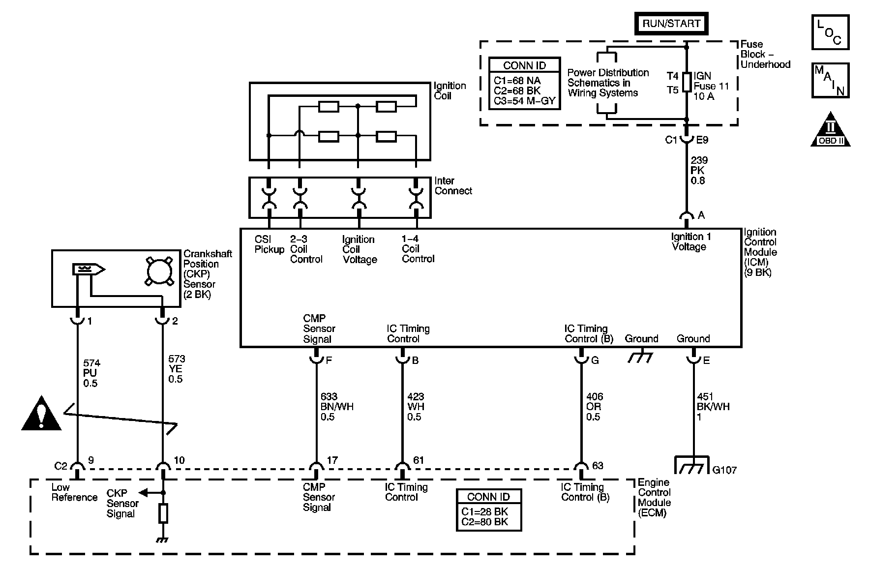
Circuit Description
The engine control module (ECM) controls spark timing and dwell under all engine running conditions. The ignition control module (ICM) has the ability to charge anddischarge the coil packs based on ECM control. The ECM uses a high control signal of near 5 volts to charge up the coil and a low control signal of near 0 voltsto discharge the coil. If the coil is charged and the control signal is low, the coil will fire through its secondary towers. During engine crank, the ECM will pulse the ignition control (IC) timing control circuit high and low to test for faults in the IC timing control circuit . If the ECM detects a short to ground in IC timing control circuit, DTC P0351 sets.
Conditions for Running the DTC
The diagnostic will run once during engine crank.
Conditions for Setting the DTC
The ECM detects a short to ground in the IC timing control circuit.
Action Taken When the DTC Sets
| • | The control module stores the DTC information into memory when the diagnostic runs and fails. |
| • | The malfunction indicator lamp (MIL) will not illuminate. |
| • | The control module records the operating conditions at the time the diagnostic fails. The control module stores this information in the Failure Records. |
| • | The driver information center, if equipped, may display a message. |
Conditions for Clearing the DTC
| • | A current DTC Last Test Failed clears when the diagnostic runs and passes. |
| • | A history DTC clears after 40 consecutive warm-up cycles, if no failures are reported by this or any other non-emission related diagnostic. |
| • | Clear the DTC with a scan tool. |
Diagnostic Aids
A short to ground on the IC timing control circuit will cause a misfire on both cylinders 1 and 4. Use a scan tool to monitor Misfire Current cylinders 1 and 4 tohelp locate an intermittent condition. Refer to Intermittent Conditions .
Step | Action | Values | Yes | No |
|---|---|---|---|---|
Schematic Reference: Engine Controls Schematics Connector End View Reference: Engine Controls Connector End Views or Engine Control Module Connector End Views | ||||
1 | Did you perform the Diagnostic System Check-Engine Controls? | -- | Go to Step 2 | |
2 |
Did the DTC fail this ignition? | -- | Go to Step 3 | Go to Diagnostic Aids |
3 | Did DTC P1351 also set this ignition? | -- | Go to Step 6 | Go to Step 4 |
4 |
Does the voltage vary within the specified range? | 0-5 V | Go to Step 7 | Go to Step 5 |
5 | Test the IC timing control circuit for a short to ground. Refer to Circuit Testing in Wiring Systems Did you find and correct the condition? | -- | Go to Step 11 | Go to Step 8 |
6 | Repair the short between the IC timing control circuit and the IC timing control B circuit. Refer to Wiring Repairs in Wiring Systems. Did you complete the repair? | -- | Go to Step 11 | -- |
7 | Test for an intermittent or poor connection at the ICM. Refer to Testing for Intermittent Conditions and Poor Connections and Connector Repairs in Wiring Systems. Did you find and correct the condition? | -- | Go to Step 11 | Go to Step 9 |
8 | Test for an intermittent or poor connection at the engine control module (ECM). Refer to Testing for Intermittent Conditions and Poor Connections and Connector Repairs in Wiring Systems. Did you find and correct the condition? | -- | Go to Step 11 | Go to Step 10 |
9 | Replace the ICM. Refer to Ignition Control Module Replacement . Did you complete the replacement? | -- | Go to Step 11 | -- |
10 | Replace the engine control module (ECM). Refer to Engine Control Module Replacement . Did you complete the replacement? | -- | Go to Step 11 | -- |
11 |
Did the DTC fail this ignition? | -- | Go to Step 2 | Go to Step 12 |
12 | Observe the Capture Info with a scan tool Are there any DTCs that have not been diagnosed? | -- | System OK | |
