For 1990-2009 cars only
Removal Procedure
- Disable the SIR system. Refer to SIR Disabling and Enabling in SIR.
- Disconnect the negative battery cable. Refer to Battery Negative Cable Disconnection and Connection in Engine Electrical.
- Remove all related panels and components.
- Repair as much of the damage as possible. Refer to Dimensions - Body .
- Remove the sealers and anti-corrosion materials from the repair area, as necessary. Refer to Anti-Corrosion Treatment and Repair in Paint and Coatings.
- Locate and drill out all the necessary factory welds.
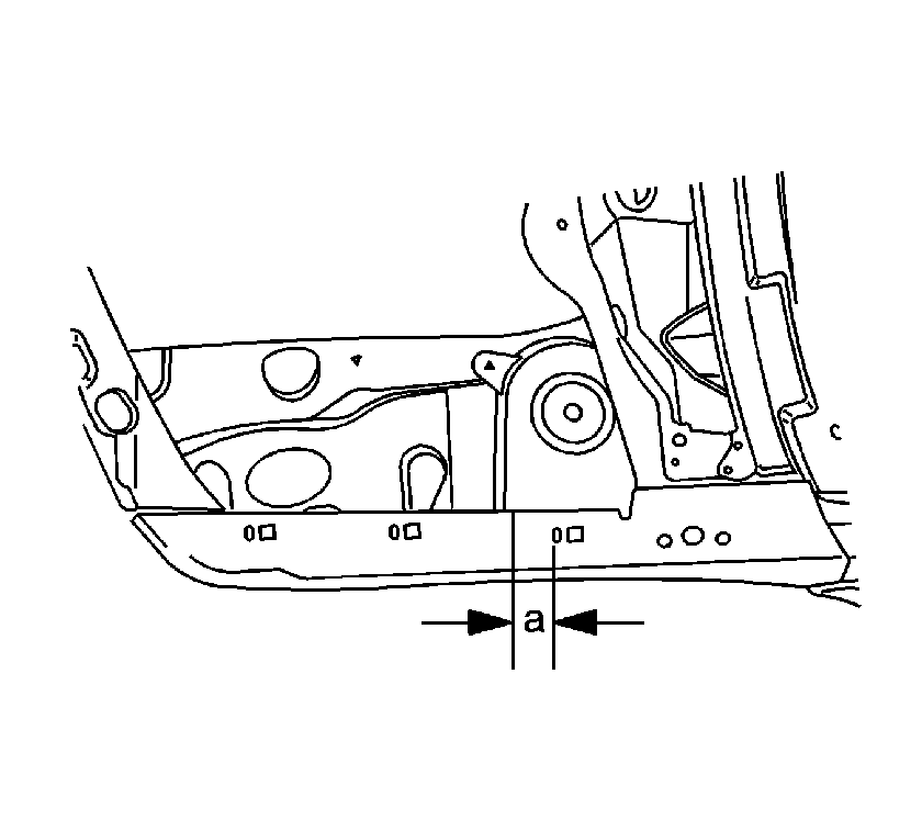
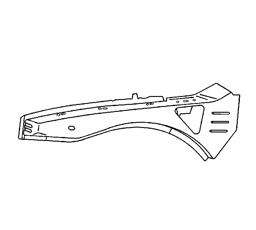
- Measure forward 75 mm (3 in) (a) of the center of the third fender bolt hole location. Mark the location.
- Using the mark made in the previous step as a starting point, use a sliding square to transfer a line on the top, side, and bottom of the rail.
- Cut the side upper rail at the marked location.
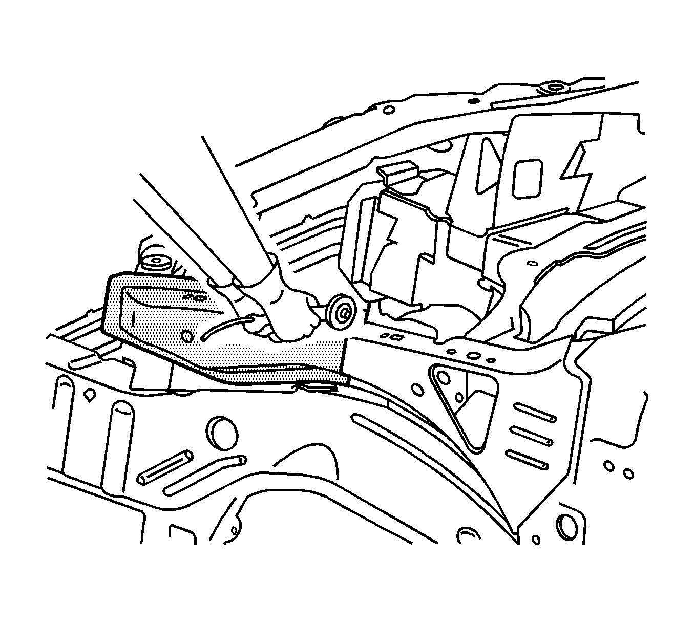
- Remove the front portion of the side upper rail.
- Drill 2 8 mm (5/16 in) plug weld holes 10 mm (1/2 in) rearward from the edge of the top, bottom, and outer side on the front edge of the remaining portion of the side upper rail on the vehicle.
Caution: Refer to Approved Equipment for Collision Repair Caution in the Preface section.
Caution: Sectioning should be performed only in the recommended areas. Failure to do so may compromise the structural integrity of the vehicle and cause personal injury if the vehicle is in a collision.
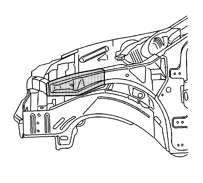
Important: Note the number and location of the factory welds for installation of the front compartment of the side upper rail.
Installation Procedure
- Measure a section on the service part that is 50 mm (2 in) (a) forward of the third fender bolt hole. Mark this section.
- Using the mark made in the previous step as a starting point, use a sliding square to transfer a line on the top, side, and bottom of the rail.
- Cut the service part at the marked location.
- Drill 8 mm (5/16 in) plug weld holes as necessary in the locations noted on the original panel.
- Prepare all mating surfaces as necessary.
- Apply 3M Weld-Thru Coating P/N 05916 or equivalent to all mating surfaces.
- Measure 25 mm (1 in) forward from the cut area. Mark the location on top of the rail.
- Using the mark made in the previous step as a starting point, use a sliding square to transfer a line on the top, side, and bottom of the rail.
- At the weld flange areas of the rail and at each radius, cut toward the scribed line. This will aid in the flange-forming process.
- Bend the cut area of the rail inward to create a 25 mm (1 in) step flange for the weld joint.
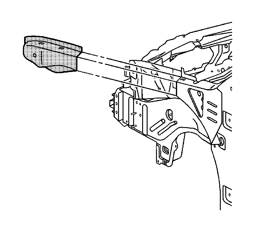
- Position the side upper rail to the vehicle using 3-dimensional measuring equipment. Clamp the rail in place.
- Stitch and plug weld accordingly.
- Clean and prepare all of the welded surfaces.
- Install all of the related panels and components.
- Apply the sealers and anti-corrosion materials to the repair area, as necessary. Refer to Anti-Corrosion Treatment and Repair in Paint and Coatings.
- Paint the repaired area. Refer to Basecoat/Clearcoat Paint Systems in Paint and Coatings.
- Connect the negative battery cable. Refer to Battery Negative Cable Disconnection and Connection in Engine Electrical.
- Enable the SIR system. Refer to SIR Disabling and Enabling in SIR.


Important: If the location of the original plug weld holes can not be determined, space the plug weld holes every 40 mm (1½ in) apart.
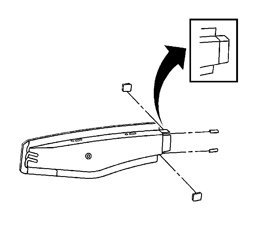
Important: Do not cut past the scribed line.

Important: Flanges on the service part will slide inside the rail portion of the vehicle.

