This repair procedure gives you the option of using an installation procedure for either metal-inert gas (MIG) welding or adhesive bonding. Refer to Metal Panel Bonding .
Removal Procedure
- Disable the SIR system. Refer to SIR Disabling and Enabling in SIR.
- Disconnect the negative battery cable. Refer to Battery Negative Cable Disconnection and Connection in Engine Electrical.
- Remove all related panels and components.
- Repair as much of the damage as possible. Refer to Dimensions - Body .
- Remove the sealers and anti-corrosion materials from the repair area, as necessary. Refer to Anti-Corrosion Treatment and Repair in Paint and Coatings.
- Locate and drill out all the necessary factory welds.
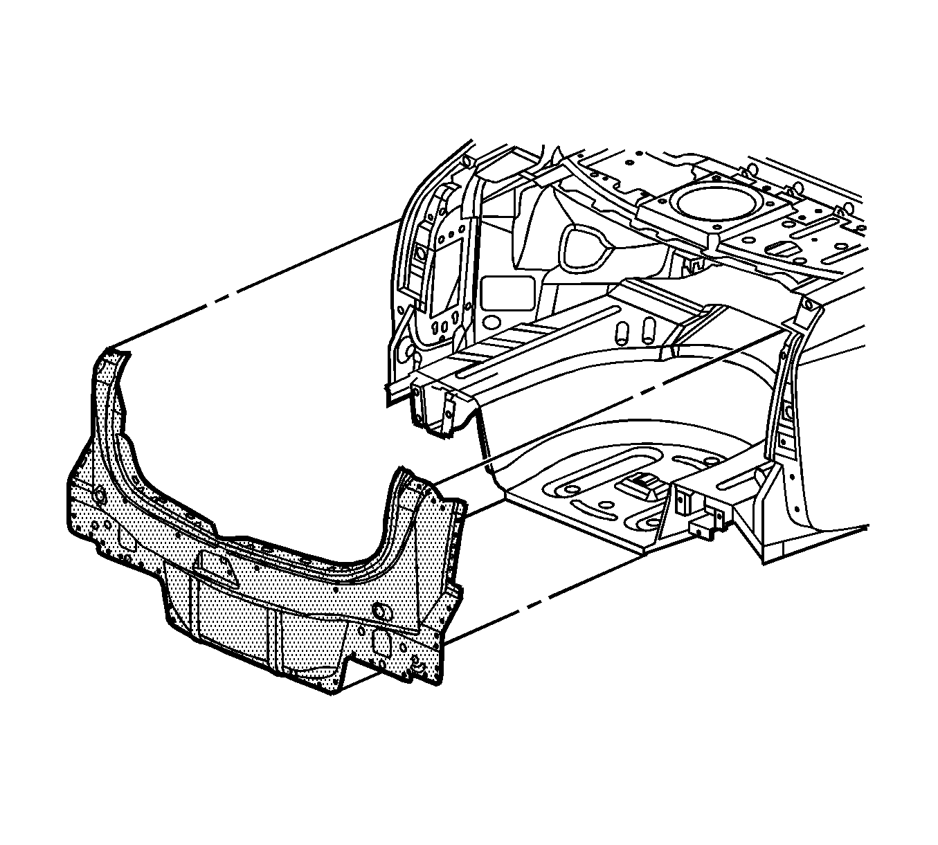
- Remove the rear end panel.
Caution: Refer to Approved Equipment for Collision Repair Caution in the Preface section.
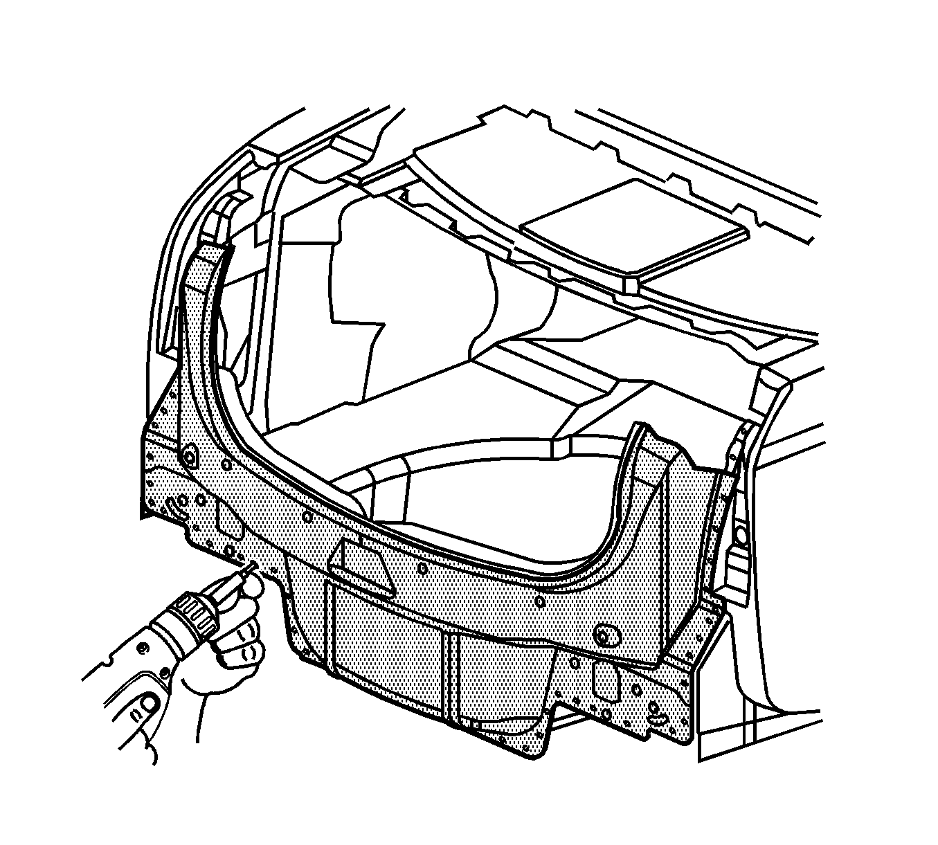
Important: Note the number and location of the factory welds for installation of the rear end panel.
Installation Procedure (Metal-Inert Gas (MIG) Welding)
- Drill 8-mm (5/16-in) plug weld holes in the service part as necessary in the locations noted from the original panel.
- Prepare all mating surfaces as necessary.
- Apply 3M® Weld-Thru coating P/N 05916 or equivalent to all mating surfaces.
- Position the rear end panel on the vehicle. Use 3-dimensional measuring equipment to inspect the panel.
- Clamp the panel in place.
- Plug weld accordingly.
- Clean and prepare all of the welded surfaces.
- Install all of the related panels and components.
- Apply the sealers and anti-corrosion materials to the repair area, as necessary. Refer to Anti-Corrosion Treatment and Repair in Paint and Coatings.
- Paint the repaired area. Refer to Basecoat/Clearcoat Paint Systems in Paint and Coatings.
- Connect the negative battery cable. Refer to Battery Negative Cable Disconnection and Connection in Engine Electrical.
- Enable the SIR system. Refer to SIR Disabling and Enabling in SIR.
Important: If the location of the original plug weld holes can not be determined, space the plug weld holes every 40 mm (1½ in) apart.
Installation Procedure (Adhesive Bonding)
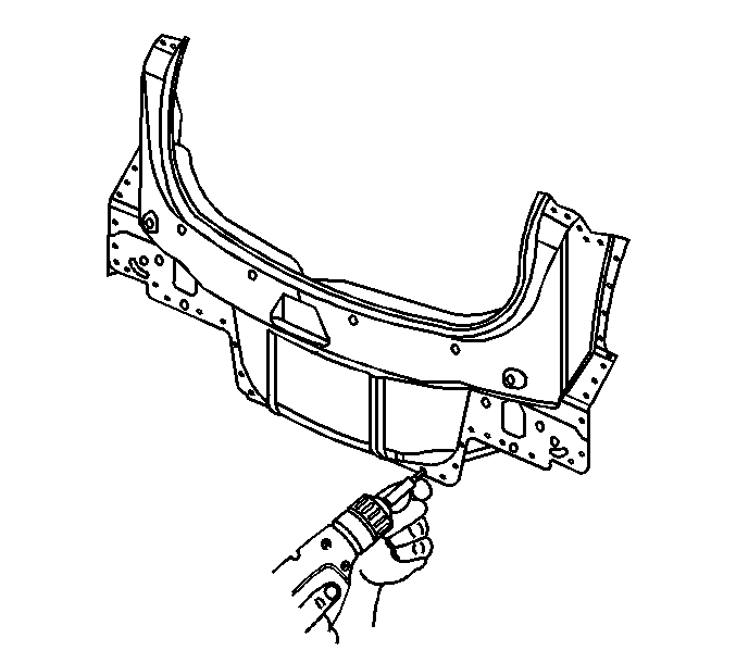
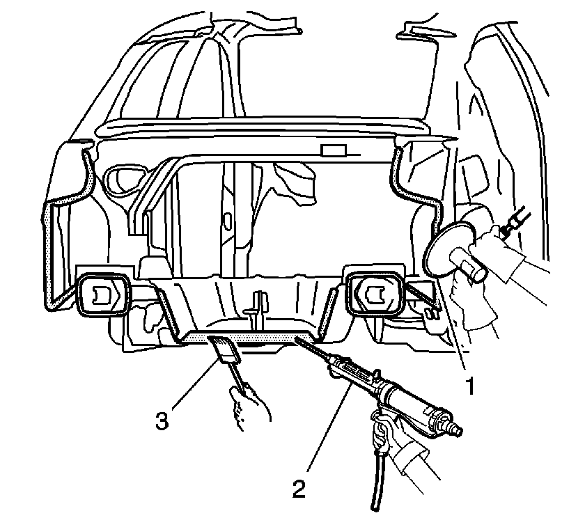
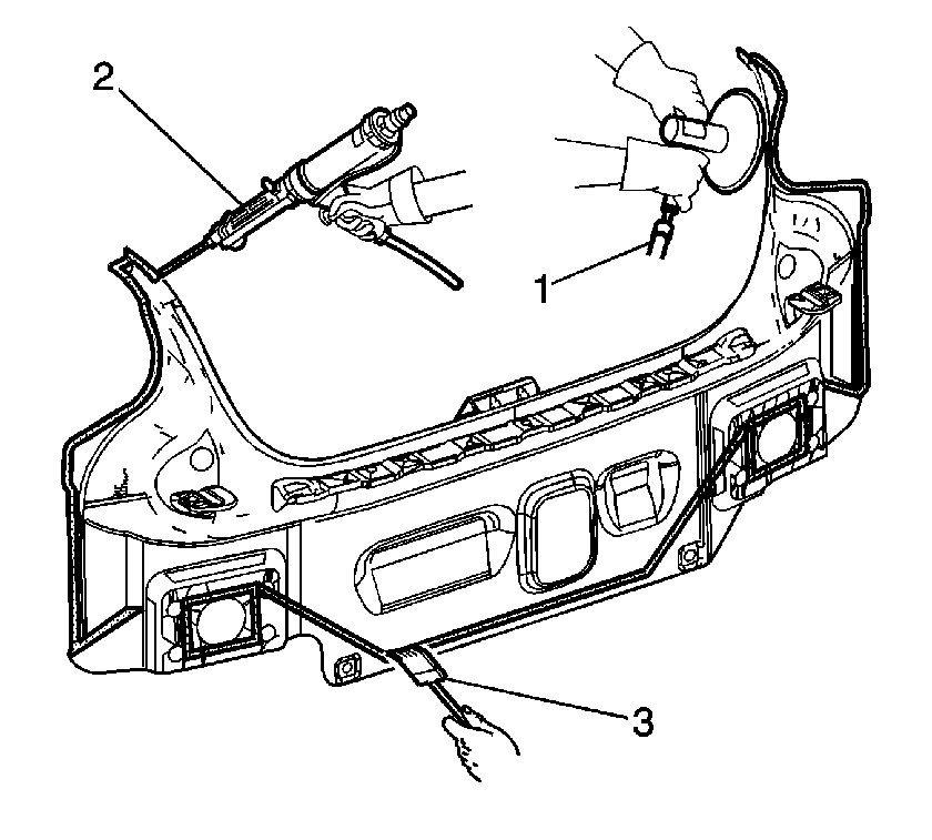
- Grind the surface of the body mating flanges (1) to bare steel.
- Grind the body rear end panel mating flanges (1) to remove the E-coating. Take care not to damage the corners or thin the metal during the grinding operation.
- Clean the mating surfaces.
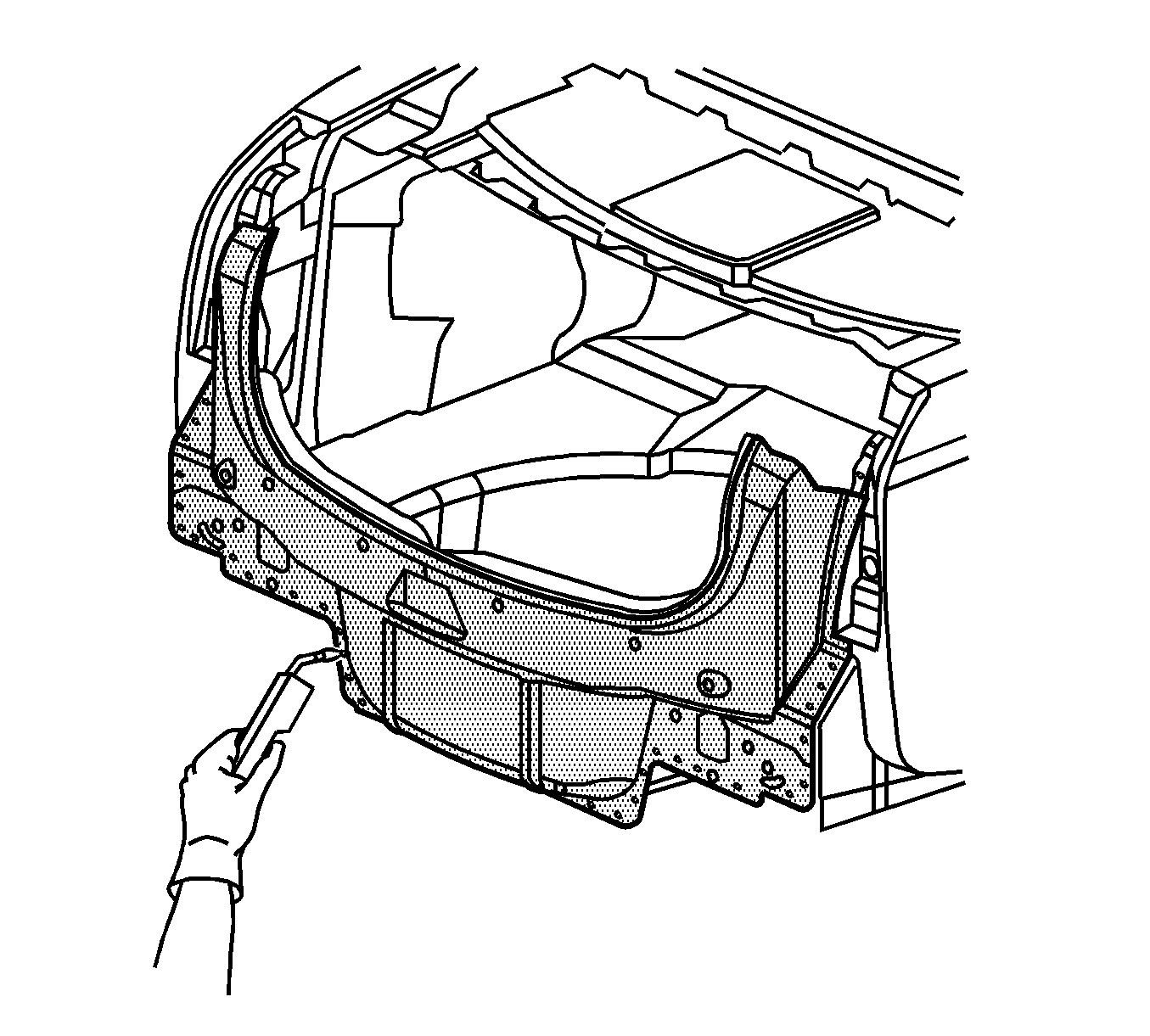
- Apply a bead of metal panel bonding adhesive (2) GM P/N 12378566/7 (Canadian P/N 88901674/5) or equivalent to a thickness of 3-6 mm (1/8 to 1/4 in), to both of the mating surfaces.
- Using a small acid brush (3), spread a coat of adhesive to cover all the bare metal surfaces to ensure corrosion protection.
- Install the body rear end panel to the vehicle.
- Clamp the body rear end panel into position as required.
- Using lacquer thinner remove the excess adhesive from the panel area.
- Apply the sealers and anti-corrosion materials to the repair area, as necessary. Refer to Anti-Corrosion Treatment and Repair in Paint and Coatings.
- Paint the repair area. Refer to Basecoat/Clearcoat Paint Systems in Paint and Coatings.
- Install all related panels and components.
- Connect the negative battery cable. Refer to Battery Negative Cable Disconnection and Connection in Engine Electrical.
- Enable the SIR system. Refer to SIR Disabling and Enabling in SIR.
Important: The adhesive has a working time of 40-50 minutes. Do not allow the adhesive to totally cure off the vehicle, as proper alignment of the panel to the body will be difficult.
Important: Do NOT pull the panels apart after joined together. Slide the panels against each other to realign the panels.
