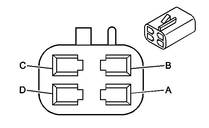
| Table 1: | Boost Gage (UXE) |
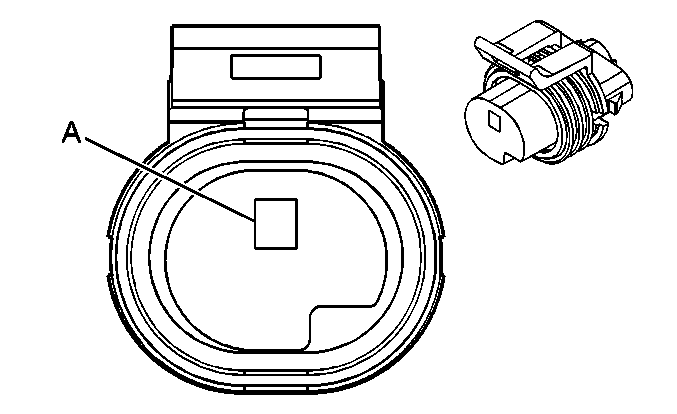
| Table 2: | Engine Oil Pressure (EOP) Switch |
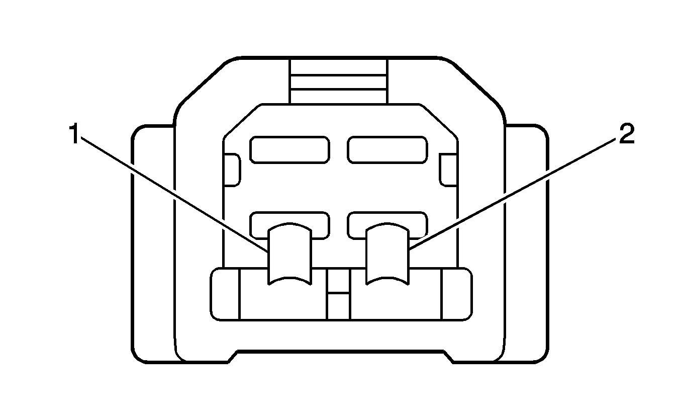
| Table 3: | Fuel Sender |
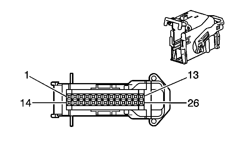
| Table 4: | Instrument Panel Cluster (IPC) |
| Table 5: | Shift Indicator Module (UXE) |
| |||||||
|---|---|---|---|---|---|---|---|
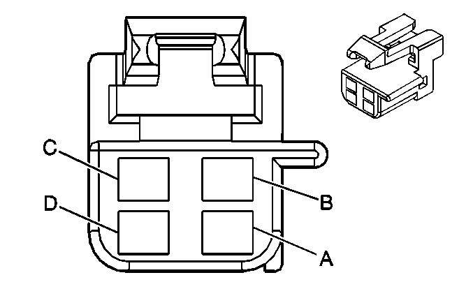
Connector Part Information |
| ||||||
Pin | Wire Color | Circuit No. | Function | ||||
A | YE | 343 | Ignition 1 Voltage | ||||
B | GY | 8 | Instrument Panel Lamps Supply Voltage | ||||
C | BK | 891 | Boost Gage Signal | ||||
D | BK/WH | 151 | Ground | ||||
| |||||||
|---|---|---|---|---|---|---|---|
Connector Part Information |
| ||||||
Pin | Wire Color | Circuit No. | Function | ||||
A | TN/BK | 231 | Oil Pressure Switch Signal | ||||
| |||||||
|---|---|---|---|---|---|---|---|
Connector Part Information |
| ||||||
Pin | Wire Color | Circuit No. | Function | ||||
1 | YE/WH | 1589 | Fuel Level Sensor Signal | ||||
2 | PK/OG | 2759 | Low Reference | ||||
| |||||||
|---|---|---|---|---|---|---|---|
Connector Part Information |
| ||||||
Pin | Wire Color | Circuit No. | Function | ||||
1 | -- | -- | Not Used | ||||
2 | PU | 1807 | Class 2 Serial Data | ||||
3-11 | -- | -- | Not Used | ||||
12 | BN/WH | 419 | MIL Control | ||||
13-14 | -- | -- | Not Used | ||||
15 | PU | 1807 | Class 2 Serial Data | ||||
16 | -- | -- | Not Used | ||||
17 | OG | 1440 | Battery Positive Voltage | ||||
18 | BK/WH | 151 | Ground | ||||
19 | -- | -- | Not Used | ||||
20 | GY | 8 | Instrument Panel Lamp Supply Voltage | ||||
21 | -- | -- | Not Used | ||||
22 | YE | 18 | Left Turn Signal Lamps Supply Voltage | ||||
23 | GY | 728 | Security Indicator Control | ||||
24 | -- | -- | Not Used | ||||
25 | D-GN | 19 | Right Turn Signal Lamps Supply Voltage | ||||
26 | -- | -- | Not Used | ||||
| |||||||
|---|---|---|---|---|---|---|---|
Connector Part Information |
| ||||||
Pin | Wire Color | Circuit No. | Function | ||||
A | YE | 343 | Ignition 1 Voltage | ||||
B | WH | 121 | Engine Speed Signal | ||||
C | BK/WH | 151 | Ground | ||||
D | GY | 8 | Instrument Panel Lamps Supply Voltage | ||||
