For 1990-2009 cars only
Removal Procedure
- Disconnect the negative battery cable. Refer to Battery Negative Cable Disconnection and Connection in Engine Electrical.
- Disable the SIR system. Refer to SIR Disabling and Enabling in SIR.
- Remove the steering column trim covers. Refer to Steering Column Trim Covers Replacement .
- Turn the ignition lock cylinder to the RUN position.
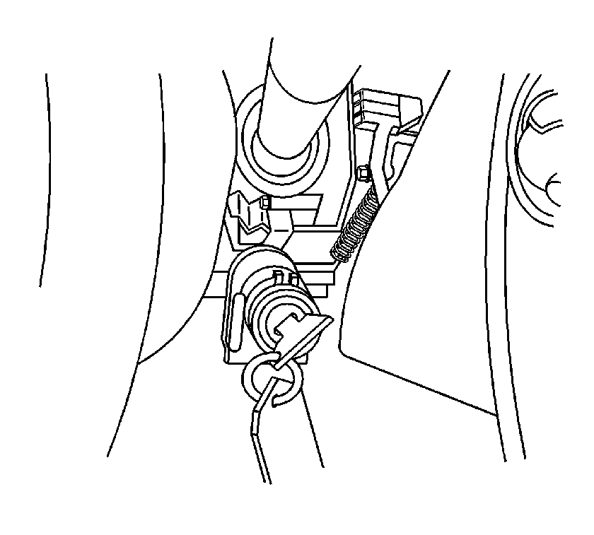
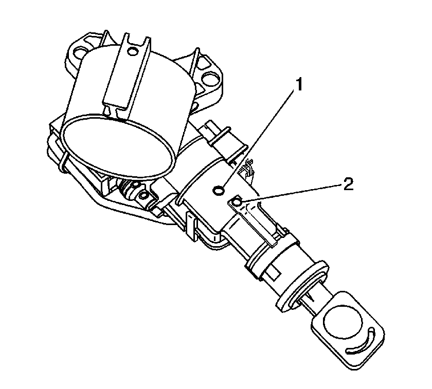
- Depress the first retainer through the lock housing access hole (2) with a small allen wrench or similar pick-type tool. The lock cylinder will back out slightly.
- Depress the second retainer through the lock housing access hole (1). The lock cylinder will back out slightly again.
- Pull the lock cylinder out enough to locate the second retainer to the lock housing access hole (2).
- Depress the retainer though the access hole (2) a second time. The ignition cylinder should release from the housing. If not, the ignition cylinder may need to be moved in and out several times to locate the retainer correctly in the hole.
- Remove the lock cylinder from the lock housing.


Important: There are two retainers on the ignition lock cylinder. Depress both retainers to remove the lock cylinder from the housing.
Installation Procedure
- Position the lock cylinder in the run position. Insert the cylinder into the lock housing.
- Rotate the lock cylinder in the housing. Verify proper rotation.
- Install the steering column trim covers. Refer to Steering Column Trim Covers Replacement .
- Enable the SIR system. Refer to SIR Disabling and Enabling in SIR.
- Connect the negative battery cable. Refer to Battery Negative Cable Disconnection and Connection in Engine Electrical.

Important: If you are installing a new lock cylinder, refer to Key and Lock Cylinder Coding in General Information.
