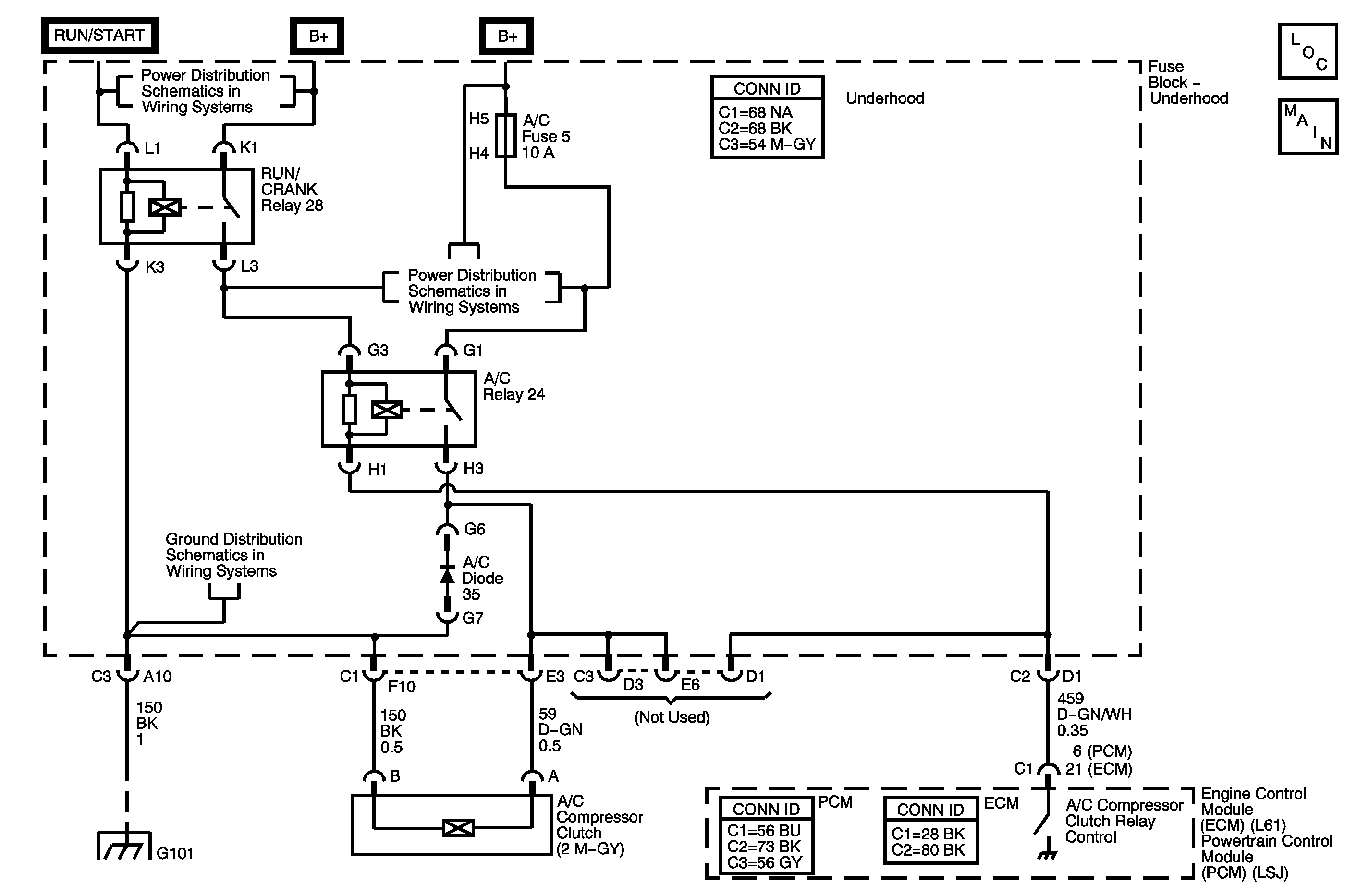
Circuit Description
Ignition voltage is supplied directly to the A/C compressor clutch relay. The engine control module (ECM) or powertrain control module (PCM) controls the relay by grounding the A/C clutch relay control circuit via an internal solid state device called a driver. The primary function of the driver is to supply the ground for the component being controlled. The driver has a fault line which is monitored by the ECM/PCM. When the ECM/PCM is commanding a component ON, the voltage of the control circuit should be near 0 volts. When the ECM/PCM is commanding the control circuit to a component OFF, the voltage potential of the circuit should be near battery voltage. If the fault detection circuit senses a voltage other than what is expected, this DTC will set.
The ECM/PCM will monitor the control circuit for the following:
| • | A short to ground |
| • | A short to voltage |
| • | An open circuit |
| • | An open relay coil |
| • | An internally shorted or excessively low resistance relay coil |
When the ECM/PCM detects any of the above malfunctions, this DTC is set and the affected driver is disabled.
DTC Descriptors
This diagnostic procedure supports the following DTCs:
| • | DTC P0646 Air Conditioning (A/C) Clutch Relay Control Circuit Low Voltage |
| • | DTC P0647 Air Conditioning (A/C) Clutch Relay Control Circuit High Voltage |
Conditions for Running the DTC
| • | The ignition voltage is between 9-16 volts. |
| • | The engine speed is more than 600 RPM. |
| • | The ECM/PCM driver transitions from ON to OFF or from OFF to ON. |
Conditions for Setting the DTC
P0646
The ECM/PCM detects a short to ground on the control circuit of the A/C compressor clutch relay.
P0647
The ECM/PCM detects a short to voltage on the control circuit of the A/C compressor clutch relay.
Action Taken When the DTC Sets
| • | The ECM/PCM will not illuminate the malfunction indicator lamp (MIL). |
| • | The ECM/PCM will store conditions which were present when the DTC set as Failure Records data only. This information will not be stored as Freeze Frame data. |
Conditions for Clearing the DTC
| • | A History DTC clears after 40 consecutive warm-up cycles have occurred without a malfunction. |
| • | The DTC can be cleared by using a scan tool. |
| • | The DTC will become history if the ECM/PCM no longer detects a failure. |
Diagnostic Aids
Important: Be sure to verify that the ECM/PCM engine grounds are secure and clean.
If DTC P0646 and P0647 cannot be duplicated, reviewing the Failure Records vehicle millage since the diagnostic test last failed may help determine how often the condition that caused the DTC to set occurs. This may assist in diagnosing the condition.
If the condition is not present, refer to Testing for Intermittent Conditions and Poor Connections in Wiring Systems.
Test Description
The numbers below refer to the step numbers on the diagnostic table.
-
Listen for an audible click when the A/C compressor clutch relay operates. Command both the ON and OFF states. Repeat the commands as necessary.
-
Tests for voltage at the coil side of the A/C compressor clutch relay. The 10-amp fuse supplies power to the coil side of the A/C compressor clutch relay.
-
Verifies that the engine control module is providing ground to the A/C compressor clutch relay.
Step | Action | Yes | No |
|---|---|---|---|
Connector End View Reference: HVAC Connector End Views | |||
1 | Did you perform the Diagnostic System Check - Vehicle? | Go to Step 2 | Go to Diagnostic System Check - Vehicle in Vehicle DTC Information |
Does the A/C compressor clutch relay turn ON and OFF with each command? | Go to Diagnostic Aids | Go to Step 3 | |
Does the test lamp illuminate? | Go to Step 4 | Go to Step 6 | |
Does the test lamp turn ON and OFF with each command? | Go to Step 7 | Go to Step 5 | |
5 | Test the control circuit of the A/C compressor clutch relay for a short to voltage, open or a short to ground. Refer to Circuit Testing and Wiring Repairs in Wiring Systems. Did you find and correct the condition? | Go to Step 11 | Go to Step 8 |
6 | Repair the battery positive voltage circuit of the A/C compressor clutch relay. Refer to Wiring Repairs in Wiring Systems. Did you complete the repair? | Go to Step 11 | -- |
7 | Inspect for poor connections at the A/C compressor clutch relay. Refer to Testing for Intermittent Conditions and Poor Connections and Connector Repairs in Wiring Systems. Did you find and correct the condition? | Go to Step 11 | Go to Step 09 |
8 | Inspect for poor connections at the harness connector of the ECM. Refer to Testing for Intermittent Conditions and Poor Connections and Connector Repairs in Wiring Systems. Did you find and correct the condition? | Go to Step 11 | Go to Step 10 |
9 | Replace the A/C compressor clutch relay. Did you complete the replacement? | Go to Step 11 | -- |
10 | Replace the PCM/ECM. Refer to Control Module References in Computer/Integrating Systems for replacement, setup, and programming. Did you complete the replacement? | Go to Step 11 | -- |
11 |
Does the DTC reset? | Go to Step 2 | System OK |
