For 1990-2009 cars only
Removal Procedure
- Disconnect the negative battery cable. Refer to Battery Negative Cable Disconnection and Connection .
- Remove the cover from the underhood electrical center.
- Remove the underhood positive battery terminal lug (1).
- Disconnect the positive battery cables (2) from the underhood electrical center.
- Remove the electric power steering (EPS) cable nut from the underhood electrical center.
- Disconnect the EPS cable (3) from the underhood electrical center.
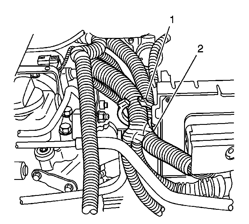
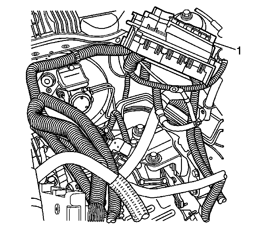
- Release the engine wiring harness retainer (1), next to the engine control module (ECM). Reposition the wiring harness (2) toward the engine.
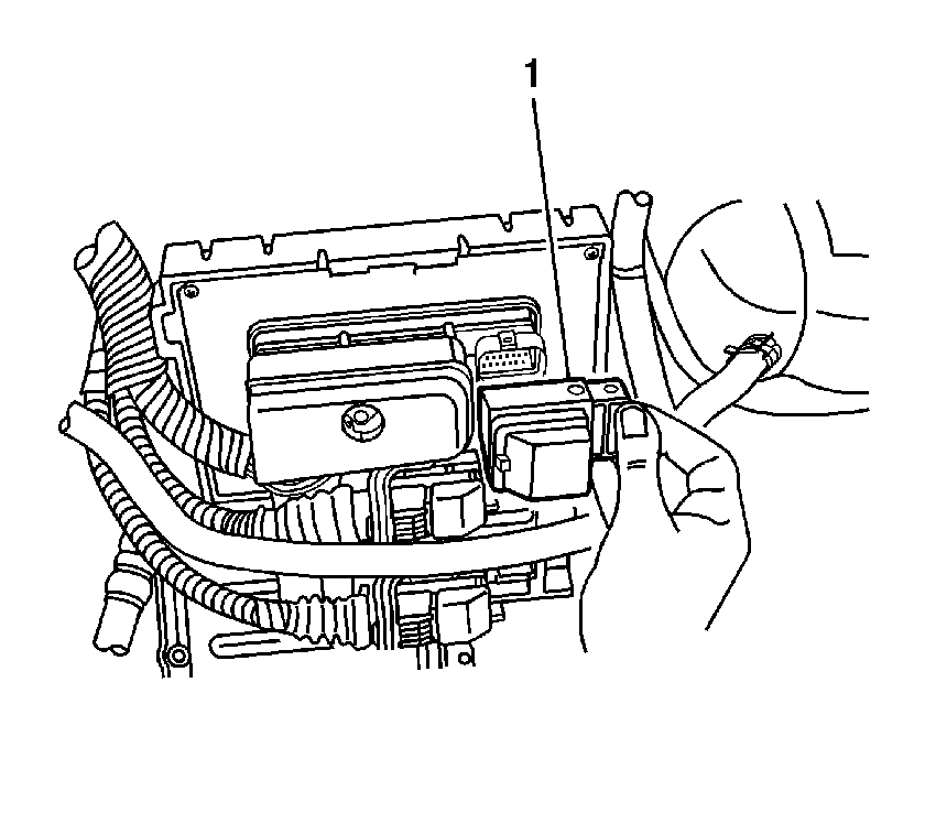
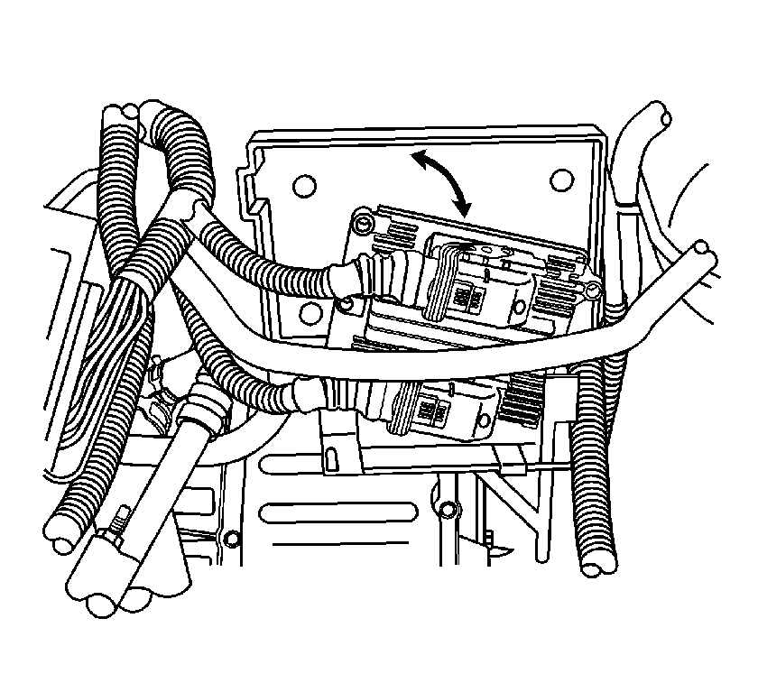
- Disconnect the outboard side electrical connector (1) from the ECM. Position the connector aside.
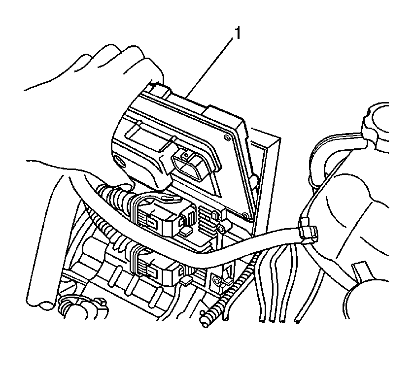
- Remove the ECM (1) from the underhood electrical center bracket, and reposition the module with harness, toward the engine.
- Remove the automatic transmission control module (TCM), if equipped, from the underhood electrical center bracket, and reposition the module with harness, toward the engine.
- Release the EPS cable retainer from the underhood electrical center bracket.
- Release the forward lamp harness retainer from the outboard side of the ECM tray.
- Release the surge tank inlet hose clip from the electrical center bracket.
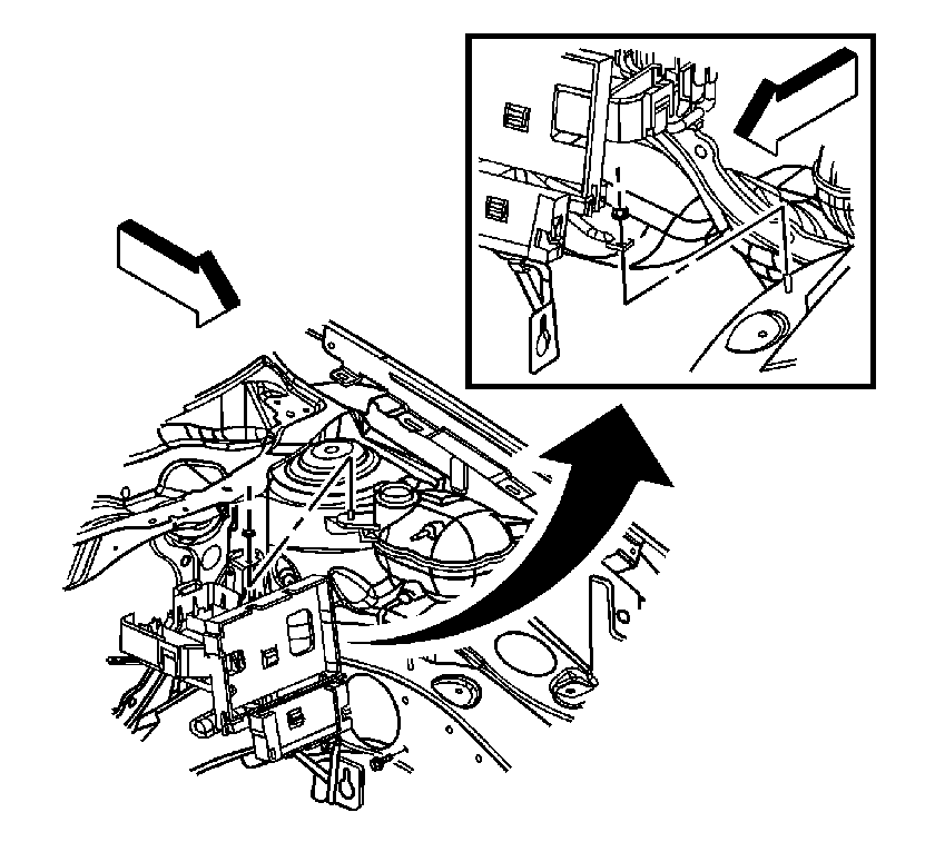
- Remove the cooling system surge tank mounting nut.
- Remove the underhood electrical center bracket mounting nut.
- Remove the electrical center bracket mounting bolt.
- Lift the bracket off of the studs and reposition the bracket slightly toward the engine.
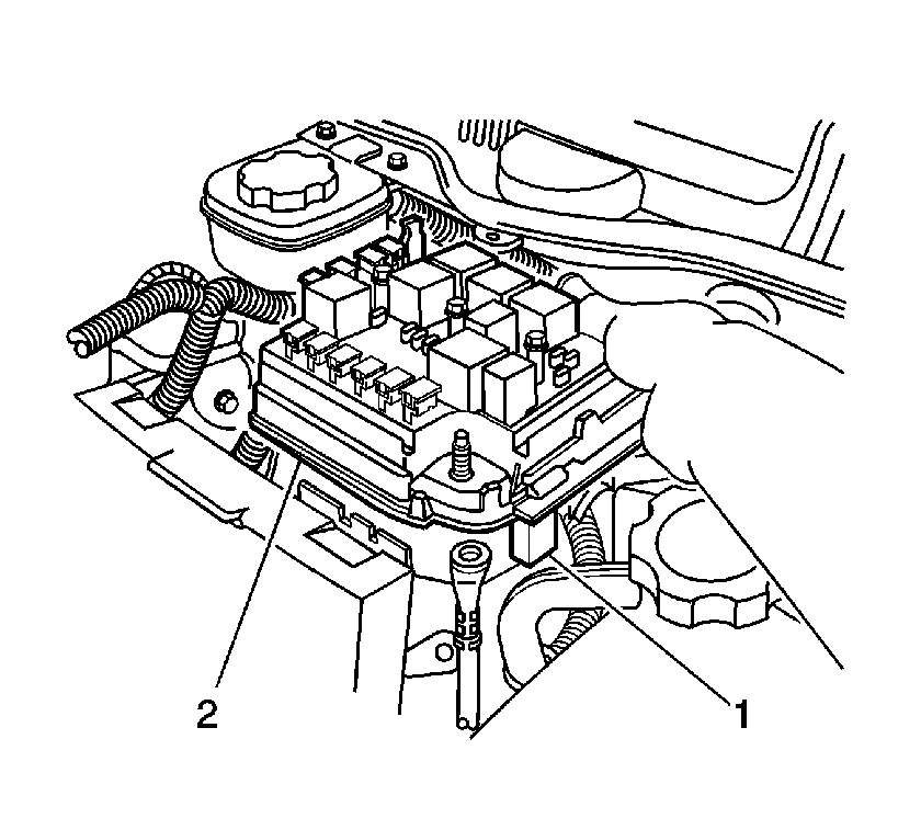
- Release the 3 locking tabs (1) securing the underhood electrical center (2) to the electrical center bracket.
- Lift the electrical center (1) away from the bracket and carefully position the electrical center (1) up and outboard, toward the hood hinge. Secure the electrical center (1) in position.
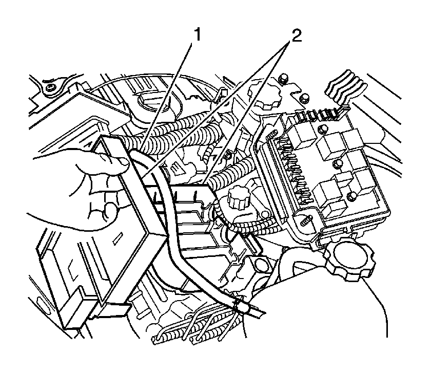
- Lift the surge tank hose (1) slightly and move the electrical center bracket (2) toward the front of the vehicle.
- Remove the bracket (2) from the vehicle.
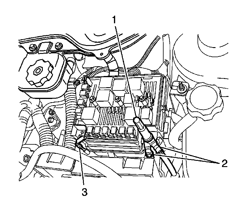
Important: Take note of the positioning of the positive battery cables before disconnecting the cables.
Installation Procedure
- Position the electrical center bracket (2) to the vehicle.
- Lift the surge tank inlet hose (1) slightly and move the electrical center bracket (2) toward the rear of the vehicle, just inboard of the installed position.
- Release the retainer from the underhood electrical center and position the electrical center (2) to the electrical center bracket.
- Secure the underhood electrical center locking tabs (1) to the electrical center bracket.
- Position the electrical center bracket onto the studs at the surge tank and on the frame rail.
- Install the underhood electrical center bracket mounting bolt. Do not tighten yet.
- Install the underhood electrical center bracket mounting nut.
- Install the cooling system surge tank mounting nut.
- Tighten the underhood electrical center bracket mounting bolt.
- Secure the forward lamp harness retainer to the outboard side of the ECM tray.
- Secure the EPS cable retainer to the underhood electrical center bracket.
- Install the TCM, if equipped, with harness to the underhood electrical center bracket.
- Install the ECM (1) with harness, to the underhood electrical center bracket.
- Connect the outboard side electrical connector (1) to the ECM.
- Install the engine wiring harness (2) to the retainer (1), next to the ECM. Secure the harness retainer (1).
- Connect the EPS cable (3) to the underhood electrical center.
- Install the electric power steering cable nut.
- Connect the positive battery cables (2) to the underhood electrical center. Position the cables as noted previously.
- Install the underhood positive battery terminal lug (1).
- Install the cover to the underhood electrical center.
- Connect the negative battery cable. Refer to Battery Negative Cable Disconnection and Connection .


Important: Ensure that the wiring harnesses are not pinched when securing the electrical center to the bracket.

Notice: Refer to Fastener Notice in the Preface section.
Tighten
Tighten the nut to 10 N·m (89 lb in).
Tighten
Tighten the nut to 10 N·m (89 lb in).
Tighten
Tighten the bolt to 25 N·m (18 lb ft).


Tighten
Tighten the nut to 10 N·m (89 lb in).
Tighten
Tighten the lug to 15 N·m (11 lb ft).
