For 1990-2009 cars only
Removal Procedure
- Raise and suitably support the vehicle. Refer to Lifting and Jacking the Vehicle .
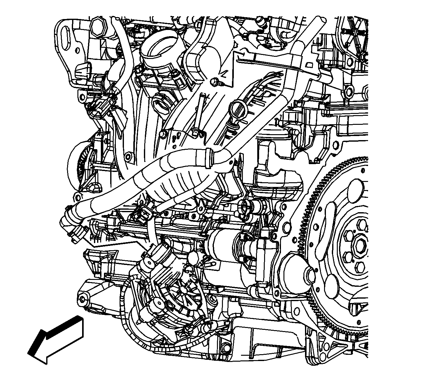
- Disconnect the secondary air injection (AIR) pump outlet hose quick connect fitting at the AIR pump. Refer to Plastic Collar Quick Connect Fitting Service .
- Lower the vehicle.
- Remove the intake manifold cover. Refer to Intake Manifold Cover Replacement .
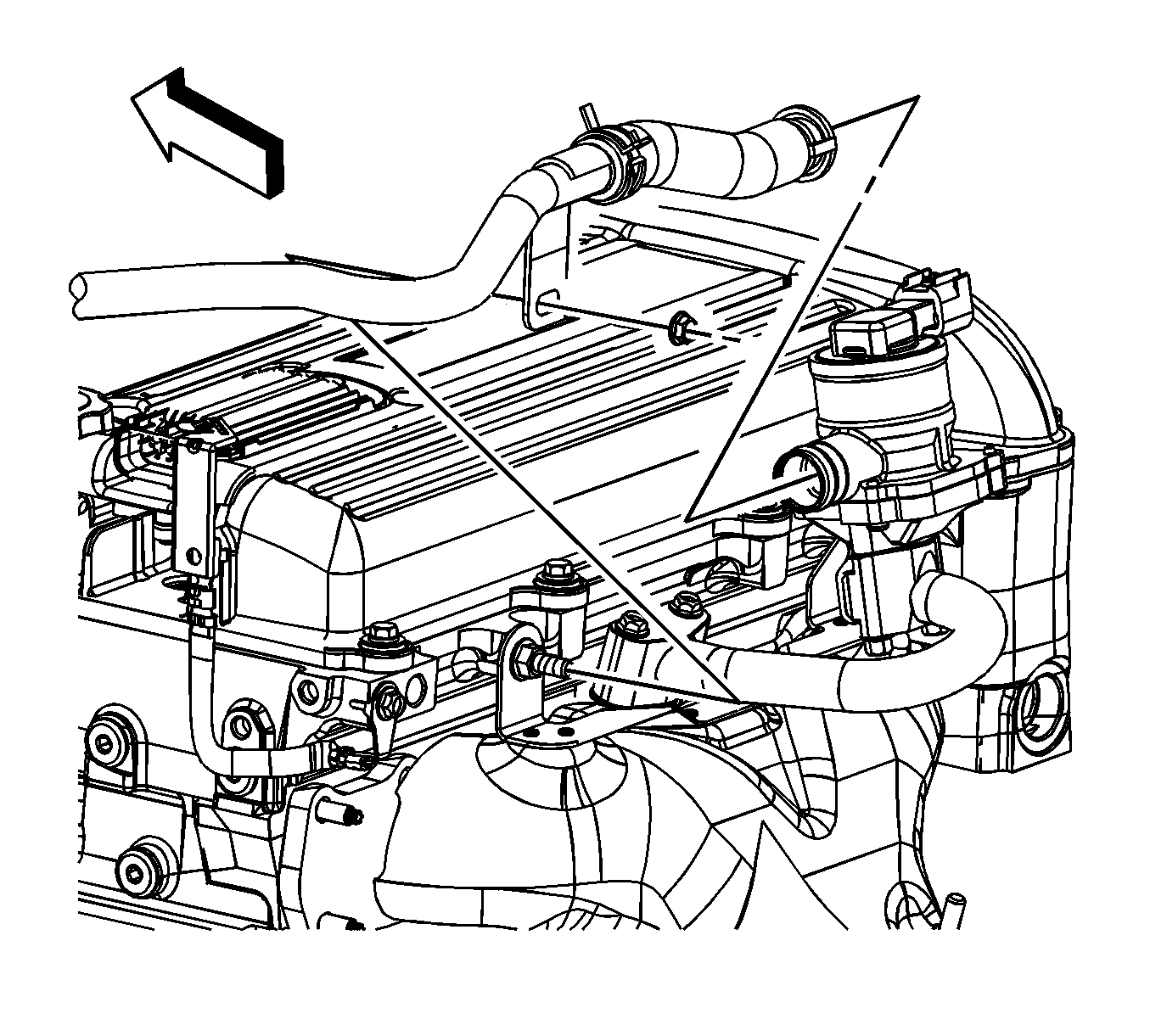
- Remove the AIR pump outlet hose bracket bolt.
- Remove the AIR pump outlet hose bracket nut.
- Disconnect the AIR pump outlet hose quick connect fitting at the AIR check valve. Refer to Plastic Collar Quick Connect Fitting Service .
- Remove the AIR pump outlet hose/pipe.


Installation Procedure
- Install the AIR pump outlet hose/pipe bracket to the exhaust manifold heat shield stud.
- Connect the AIR pump outlet hose quick connect fitting at the AIR check valve. Refer to Plastic Collar Quick Connect Fitting Service .
- Install the AIR pump outlet hose bracket nut.
- Install the AIR pump outlet hose bracket bolt.
- Install the intake manifold cover. Refer to Intake Manifold Cover Replacement .
- Raise and suitably support the vehicle.
- Connect the AIR pump outlet hose quick connect fitting at the AIR pump. Refer to Plastic Collar Quick Connect Fitting Service .
- Lower the vehicle.

Notice: Refer to Fastener Notice in the Preface section.
Tighten
Tighten the nut to 10 N·m (89 lb in).

Tighten
Tighten the bolt to 20 N·m (15 lb ft).
