Compressor Clutch Assembly Replacement 2.0L (LSJ)
Tools Required
| • | J 37872 Universal Spanner Wrench |
| • | SA9149AC-8 Snap Ring Pliers |
Removal Procedure
- Remove the compressor. Refer to Air Conditioning Compressor Replacement .
- Remove and discard the compressor clutch plate bolt. Use the J 37872 to hold the compressor clutch plate from turning.
- Remove the compressor clutch plate.
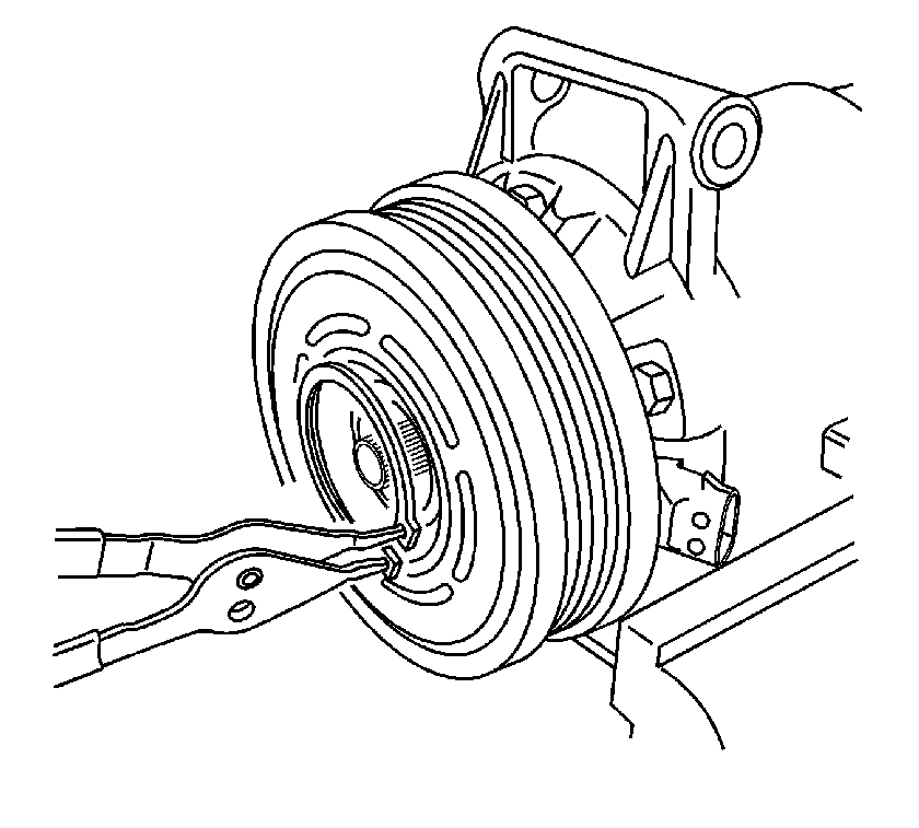
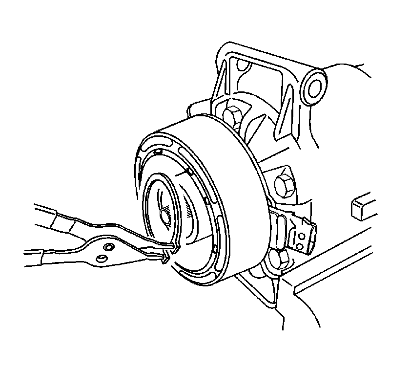
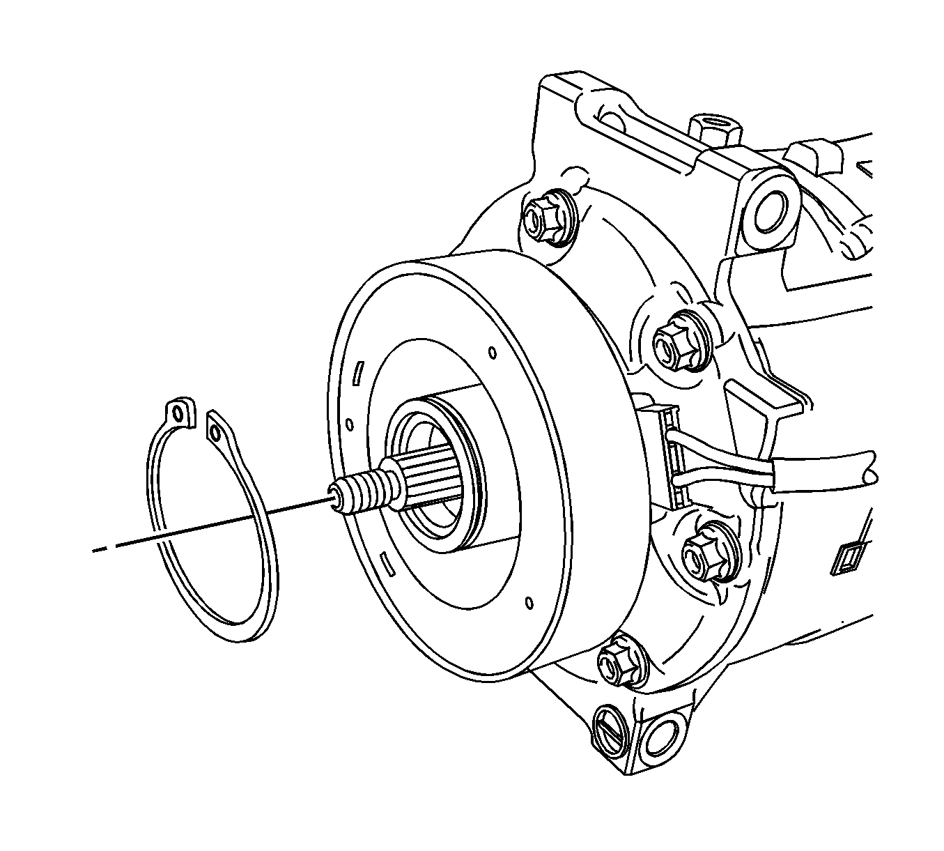
- Remove the compressor pulley snap ring using SA9149AC-8 .
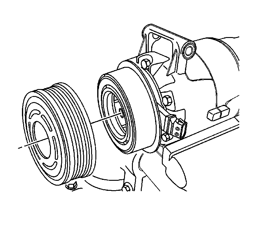
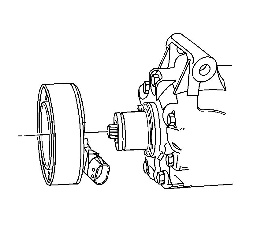
- Slide the compressor pulley off of the compressor.
- Remove the compressor clutch coil snap ring using SA9149AC-8 .
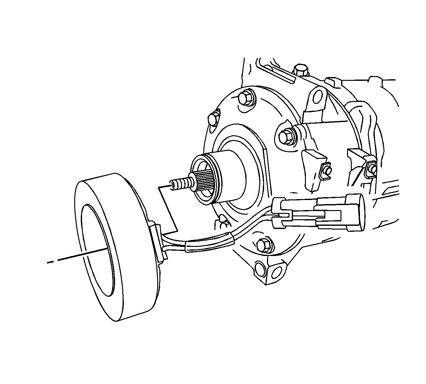
- Slide the compressor clutch coil off of the compressor.
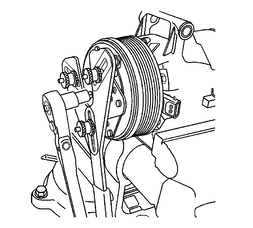
Important: Remove the 3 adjustable dowels from the Universal Spanner Wrench.
Install three 5/16 x 1 inch bolts in place of the dowels.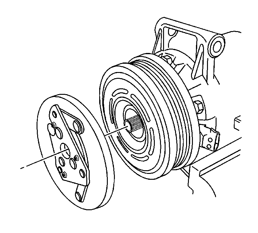
Installation Procedure
- Carefully clean the clutch plate bolt threads with a M6x1.0 tap. Carefully blow out debris with compressed air.
- Slide the compressor clutch coil onto the compressor.
- Install the compressor clutch coil snap ring using SA9149AC-8 .
- Slide the compressor pulley onto the compressor.
- Install the compressor pulley snap ring using SA9149AC-8 .
- Place a small amount of oil on the 0.4 mm (0.016 in) air gap shim and place inside the clutch drive plate.
- Install the compressor clutch plate.
- Measure the air gap between the pulley and the drive plate. Adjust the shims to achieve a 0.3-0.6 mm (0.012-0.024 in) air gap.
- Make certain that the new drive plate bolt has colored adhesive on at least 5 threads. Install the clutch drive plate bolt. Use the J 37872 to hold the compressor clutch plate from turning.
- Install the compressor. Refer to Air Conditioning Compressor Replacement .
- Evacuate and charge the refrigerant system. Refer to Refrigerant Recovery and Recharging .
- Leak test the fittings using the J 39400-A .


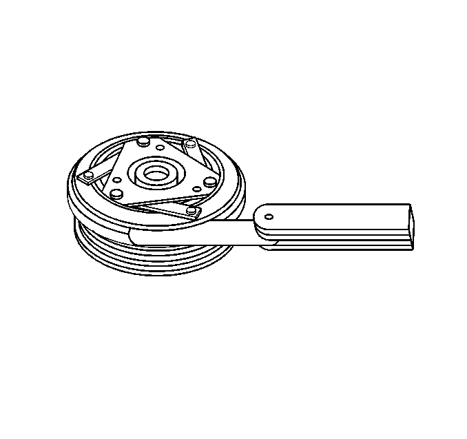
Important: Make certain that the drive plate does not drag against the pulley when the pulley is rotated.
Notice: Refer to Fastener Notice in the Preface section.

Tighten
Tighten the compressor clutch drive plate bolt to 12 N·m (106 lb in).
Compressor Clutch Assembly Replacement LE5, L61
Tools Required
Removal Procedure
- Remove the A/C compressor from the vehicle. Refer to Air Conditioning Compressor Replacement
- Mount the A/C compressor in a compressor stand or other suitable support fixture.
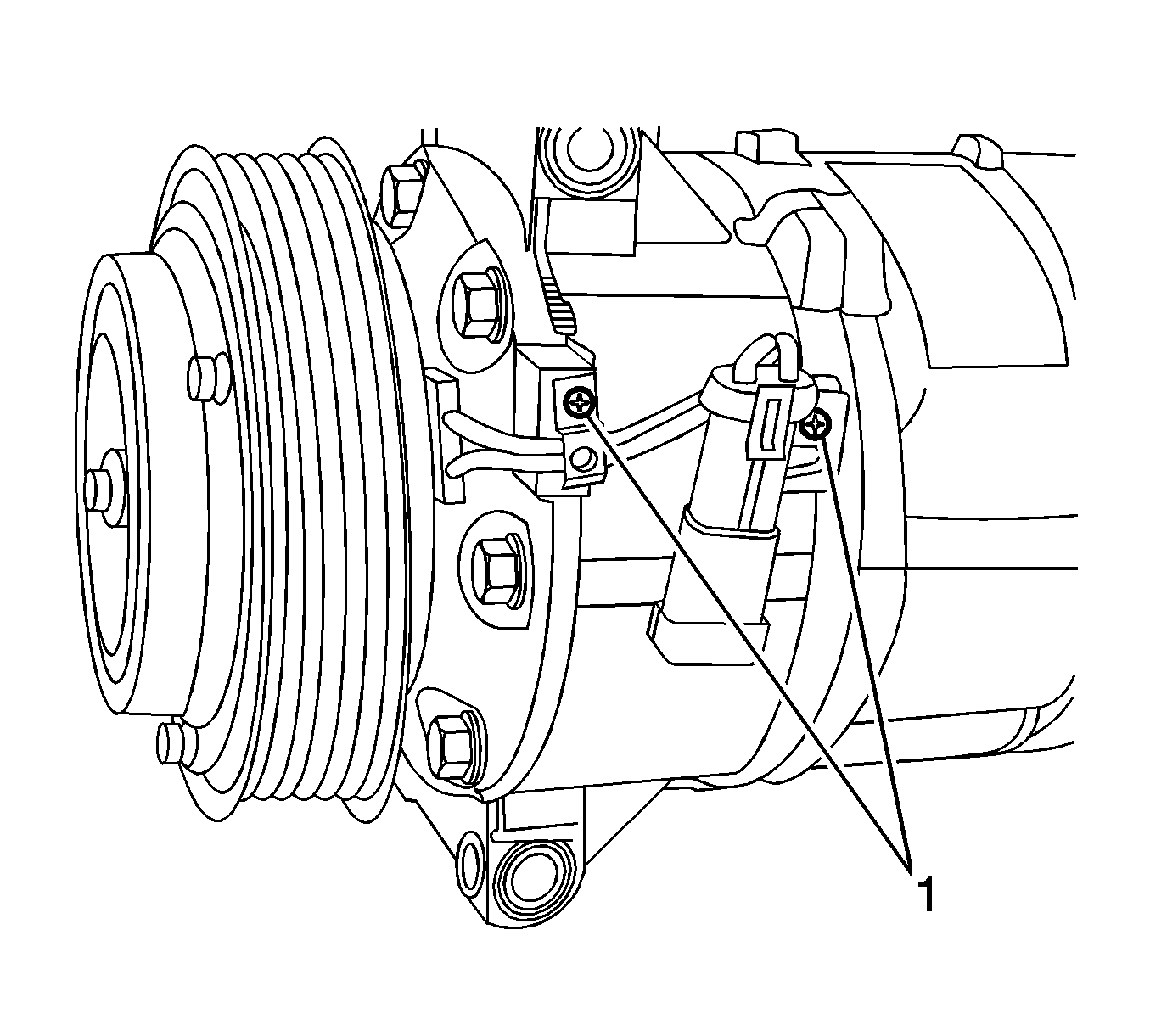
- Remove the A/C compressor clutch assembly wiring harness retaining screws (1).
- Using J 37872 , hold the A/C compressor clutch assembly from rotating and remove the retaining nut from the A/C compressor shaft.
- Remove the clutch plate from the A/C compressor.
- Using J 6083 , remove the clutch pulley snap ring retainer.
- Use an appropriate sized impact socket sized to sit on the compressor hub to protect the compressor shaft during pulley removal.
- Using J 41816 or equivalent, remove the clutch pulley from the A/C compressor.
- Using J 6083 , remove the clutch coil snap ring retainer.
- Remove the clutch coil.
- Using a small flat bladed object, gently pry up on the shaft seal (felt wick) retainer and remove.
Important:
Cap or tape the A/C compressor ports to ensure:
• Contamination or debris does not enter the A/C compressor. • PAG oil is not lost once the A/C compressor is fixed into position.
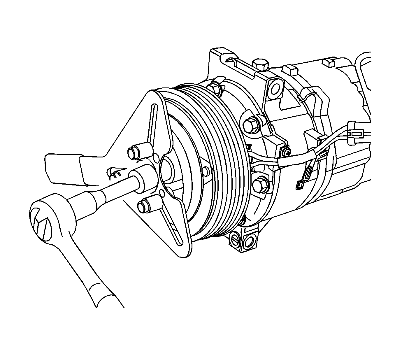
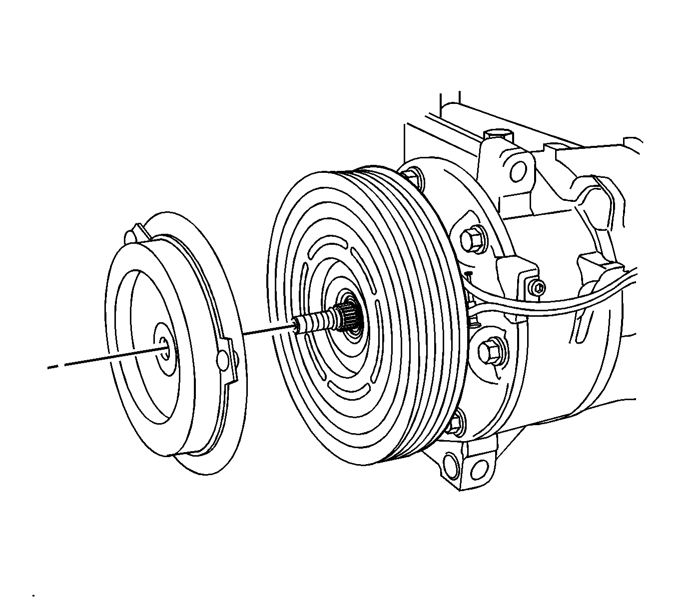
Important: Do not drop, lose or misplace the clutch shim from the A/C compressor shaft when removing the clutch.
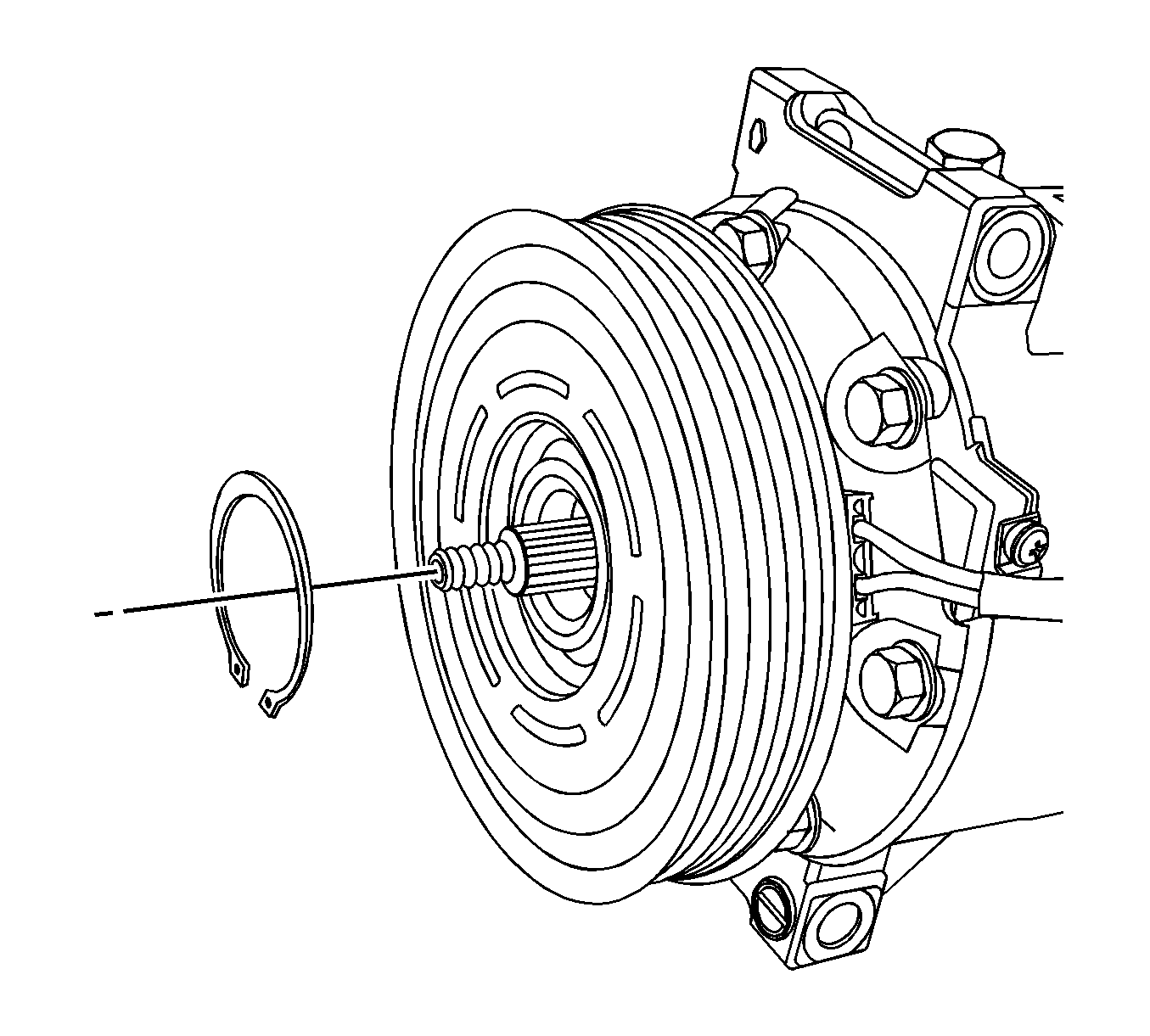
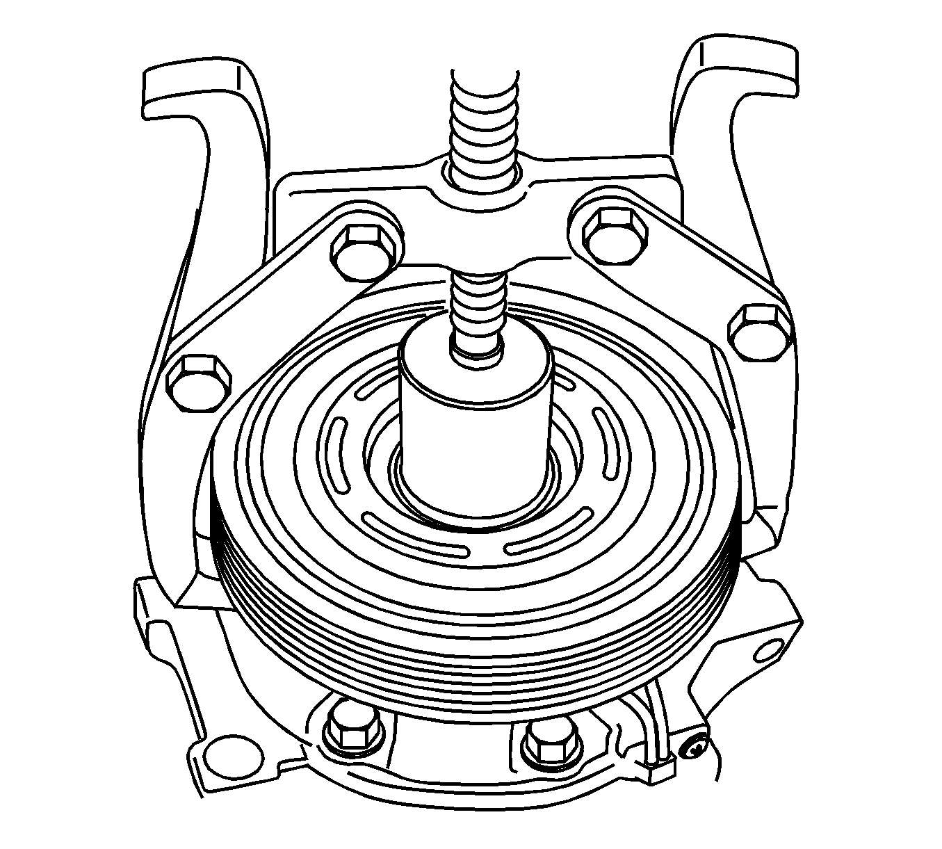
Important: Do not press on the A/C compressor shaft or compressor damage could occur.
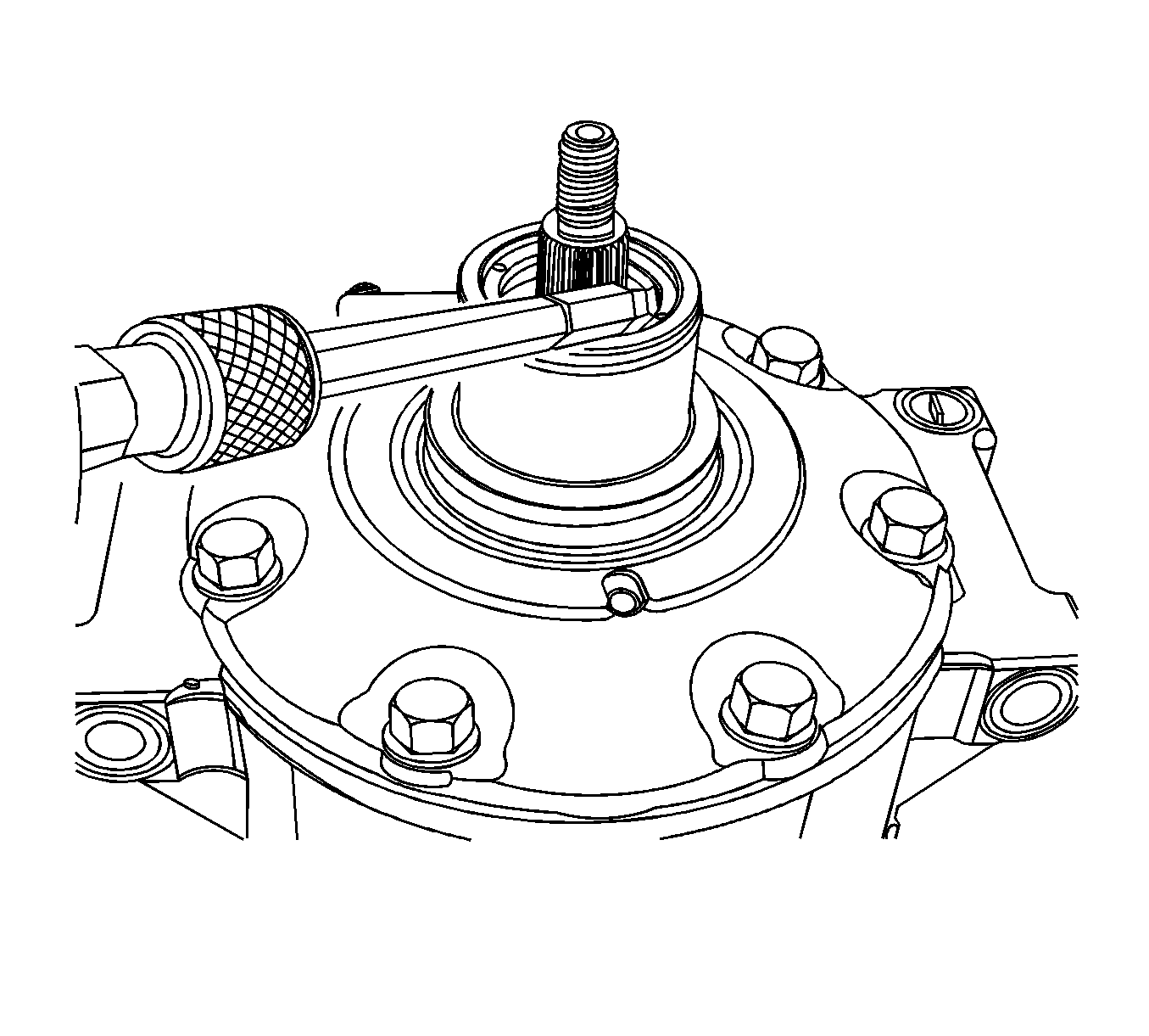
Important: Do not make contact with the A/C compressor shaft threads or damage the lip seal during shaft seal (felt wick) removal.
Installation Procedure
- Using an appropriate sized socket to seat on the shaft seal (felt wick) outer retainer, install the shaft seal (felt wick) into the A/C compressor. The retainer should be flush with the housing.
- Ensure that the all mounting surfaces and/or threads on the A/C compressor and clutch assembly are completely free of debris and contamination prior to reassembly.
- Install the clutch coil.
- Using J 6083 , install the clutch coil snap ring retainer.
- Using an appropriate sized impact socket to seat on the inner bearing race, install the clutch pulley onto the A/C compressor using a hydraulic press.
- Using J 6083 , install the clutch pulley snap ring retainer.
- Install the A/C compressor clutch assembly wiring harness retaining screws (1).
- Install the previously used clutch shim if removed from the A/C compressor shaft.
- Install the clutch plate onto the A/C compressor.
- Install the ORIGINAL clutch plate retaining nut and using the J 37872 , hold the A/C compressor clutch from rotating.
- 11) Measure the air gap between the clutch plate and the clutch pulley. The air gap should be 0.3-0.7mm (0.012-.028 in). If the air gap is not within specification, remove shaft nut and clutch plate and use an alternate shim included in the service kit to achieve the proper air gap.
- Remove the ORIGINAL clutch plate retaining nut and install the NEW nut provided in the kit.
- Remove the A/C compressor from the compressor stand or other suitable support fixture and remove the cap or tape from the A/C compressor ports.
- Install the A/C compressor to the vehicle. Refer to Air Conditioning Compressor Replacement
- Leak test the fittings using the J 39400-A
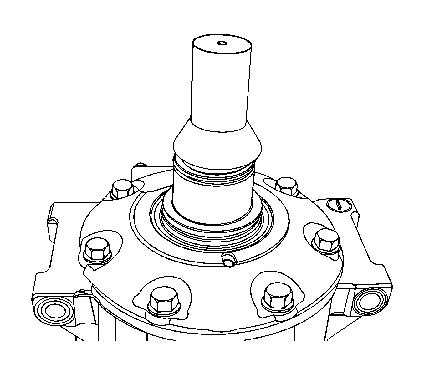

Important: Align the dimple on the clutch coil with the notch in the A/C compressor casting to ensure proper orientation. Failure to align the clutch coil assembly will cause the snap ring retainer not to seat properly.

Important: Ensure that the clutch coil snap ring is fully seated within the bore.
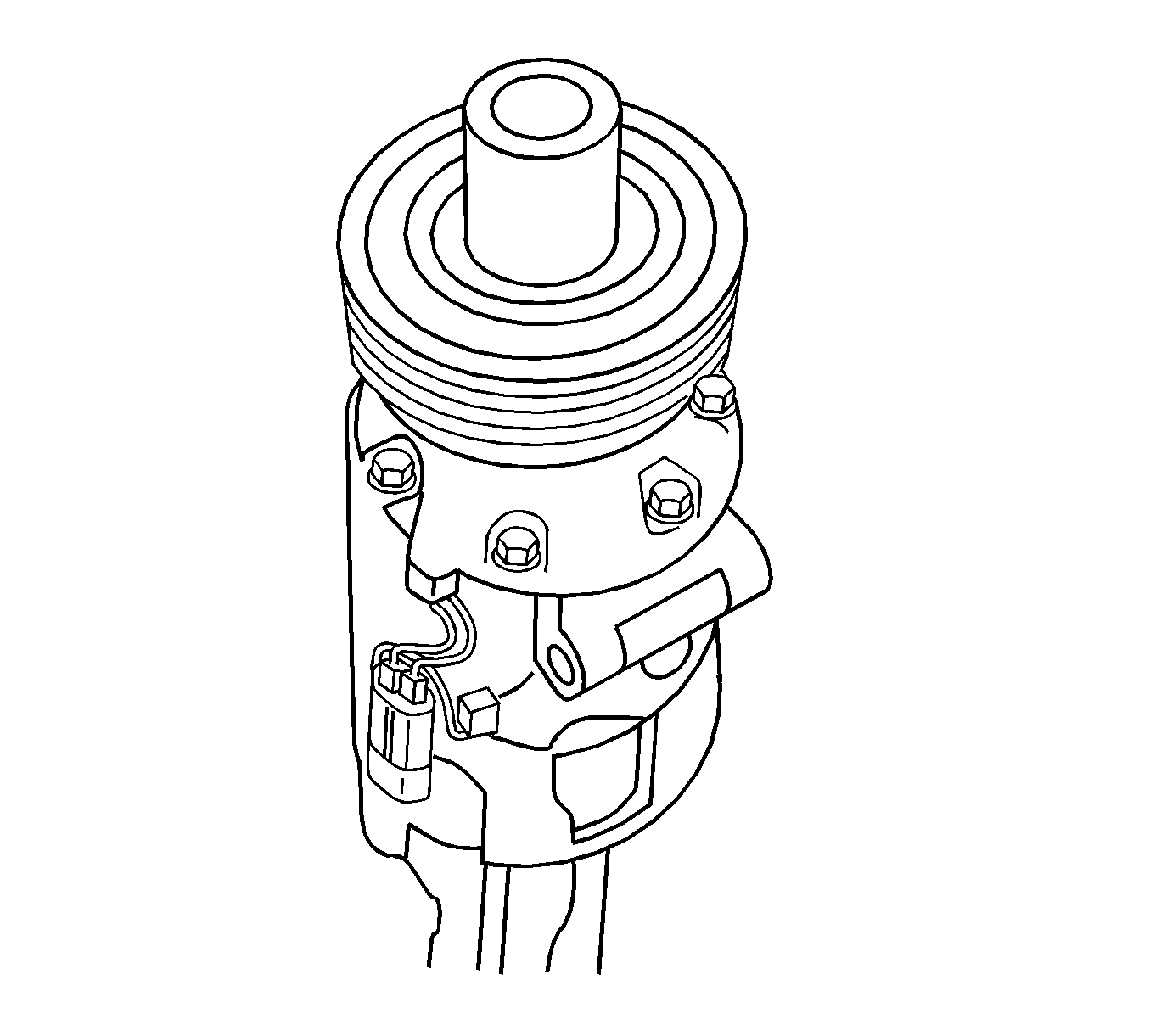
Important: Do not press on the seal, pulley or outer bearing race.

Important: Ensure that the clutch pulley snap ring is fully seated within the bore.

Tighten
Tighten the screws to 2.3 N·m (22 lb in).


Tighten
Tighten the screws to 25 N·m (18 lb ft).
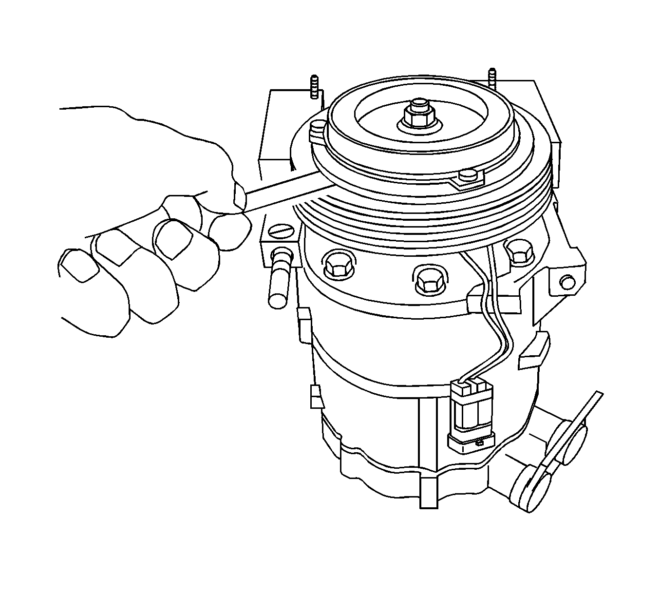
Important: Make certain that the clutch plate does not drag or interfere with the pulley when rotated.
Tighten
Tighten the screws to 25 N·m (18 lb ft).
