Circuit Description
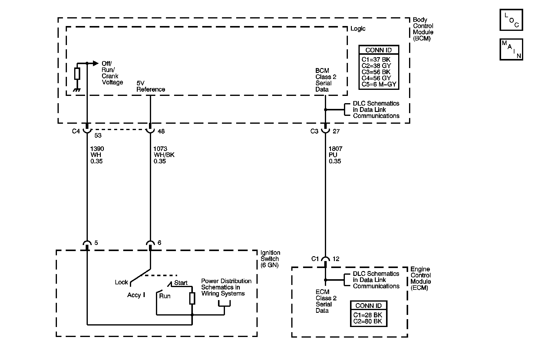
The Passlock system is provided in order to prevent vehicle theft if the ignition lock cylinder is forced to rotate. The Passlock controller reads the coded Passlock data signal. The data consists of a voltage generated by a voltage divider network created between the Passlock assembly and the Passlock controller. If the data is correct , indicating rotation of the lock cylinder with the proper mechanically cut key, then the Passlock controller sends a password to the Powertrain controller via serial data to indicate that engine starting should be allowed. The Passlock controller also interfaces with the driver displays subsystem to indicate, via the security indicator, the Passlock subsystem's status and acute subsystem failures.
DTC Descriptor
This diagnostic procedure supports the following DTC:
DTC B3033 Security System Indicates Tamper
Conditions for Setting the DTC
| • | The analog voltage signal sampled at the body control module (BCMs) Passlock detection circuit is a tamper signal indicating a Passlock tamper. |
| • | Condition must be present during an engine start attempt. |
Action Taken When the DTC Sets
When attempting to start the engine and the Passlock sensor sends a tamper signal, the BCM will take one of two actions:
| • | If the BCM programming mode is not active AND the BCM is not in fail enable mode, then: |
| - | The BCM stores DTC B3033 in memory. |
| - | The BCM flashes the security indicator. |
| - | The BCM sends a message to the engine controller via serial data link to disable engine operation. |
| - | The BCM disables sampling of the Passlock sensor voltage signal for a time-out period of ten minutes. |
| - | If the ignition switch is left on for at least ten minutes, the BCM enters the theft deterrent re-learn mode. |
| • | If the BCM programming mode is active AND the BCM is in fail enable mode, then: |
| - | The BCM stores DTC B3033 in memory. |
| - | The BCM illuminates the security indicator. |
| - | The BCM will send a message to the engine controller via serial data to allow normal engine operation. |
Conditions for Clearing the DTC
| • | A current DTC B3033 clears when the BCM detects a valid Passlock sensor code. |
| • | When the BCM detects a valid code from the Passlock sensor, the ignition switch must be cycled from OFF to ON before this DTC can change from a current DTC to a history DTC. |
| • | A history DTC clears after 100 consecutive ignition cycles if the condition for the malfunction is no longer present. |
Diagnostic Aids
| • | A malfunctioning Passlock sensor may cause an intermittent malfunction to occur. |
| • | If the SECURITY indicator is flashing, the BCM's Passlock has entered a vehicle disable state that will last approximately 10 minutes. Disconnecting the battery will not clear the timer sequence, it will resume when battery power is restored. Even if a proper Passlock sensor code is read during the vehicle disable period, the vehicle will not start until the 10 minute time period has elapsed. After this 10 minute time period, the SECURITY indicator will change from a flashing state to a solid on state. At this time, the BCM enters the theft deterrent re-learn mode. The engine will start if the BCM detects the correct Passlock sensor code. |
| • | Check for poor connections at both the BCM and the ignition switch which could cause an incorrect Passlock sensor voltage signal or intermittent malfunction. |
Test Description
The number below refers to the step number on the diagnostic table.
Step | Action | Yes | No |
|---|---|---|---|
1 | Did you perform the Diagnostic System Check - Vehicle? | Go to Step 2 | |
2 |
Does the scan tool display DTC B3033 as a current DTC? | Go to Step 3 | Go to Testing for Intermittent Conditions and Poor Connections in Wiring Systems |
Inspect the off/run/crank voltage circuit for a short to ground. Refer to Circuit Testing and Wiring Repairs in Wiring Systems. Did you find and correct the condition? | Go to Step 7 | Go to Step 4 | |
4 | Inspect for poor connections at the Passlock sensor. Refer to Testing for Intermittent Conditions and Poor Connections and Connector Repairs in Wiring Systems. Did you find and correct the condition? | Go to Step 7 | Go to Step 5 |
5 | Replace the Passlock sensor. Refer to Ignition and Start Switch Replacement in Steering Wheel and Column. Did you complete the replacement? | Go to Step 6 | -- |
6 | Perform the Passlock learn procedure. Refer to Programming Theft Deterrent System Components . Did you complete the repair? | Go to Step 7 | -- |
7 | You may have to wait up to 10 minutes in order to reset the body control module (BCM) and synchronize all of the Passlock components.
Does the DTC reset? | Go to Step 3 | System OK |
