Erratic Front Turn Signal Operation When Using A Cell Phone Charger in Either Accessory Power Outlet (Install Capacitor in Accessory Outlet Wiring)

| Subject: | Erratic Front Turn Signal Operation When Using a Cell Phone Charger in Either Accessory Power Outlet (Install Capacitor In Accessory Outlet Wiring) |
| Models: | 2003-2006 Saturn ION |
This bulletin is being revised to add model years. Please discard Corporate Bulletin Number 03-08-42-009A (Section 03 -- Body and Accessories).
Condition
Some customers may comment that one or both front turn signals are operating erratically. They may also comment that the corresponding rear turn signal and turn signal indicator in the I/P cluster flashes twice as fast. The lamps will come back on when the ignition is cycled to "OFF" and then to "RUN" but may still go off again.
Cause
Important: Not all chargers create the amount of noise necessary to cause this concern. Use of a different charger may eliminate the concern.
This condition may be caused by the use of a charger in either the front or rear accessory outlet. Some chargers can create excessive noise through the power line between the accessory outlet and the Integrated Body Control Module (IBCM) where the power fuses are located. The amount of noise from the charger can vary depending on the state of charge of the receiving device (less noise when the device is near full charge capacity) or type of charger. Just having the charger installed in the accessory power outlet without a device attached to it should not cause the lamps to go out.
Correction
Install 220-microfarad 35V capacitor, P/N 10395194, in the wiring of the affected outlets.
Step | Action | Yes | No |
|---|---|---|---|
1 |
Do both I/P turn signal indicators flash at normal speed? | Go to Step 2 | Refer to Corporate Bulletin Number 04-08-42-002A |
2 | Does the customer use a cell phone and have a charger for the car? | Go to Step 3 | Check for intermittent connections in the wiring harness from the Body Control Module (BCM) to the turn signal socket at the headlamp assembly |
3 |
Does either DRL turn off? (May take up to 20 minutes) Important: ION3 vehicles are equipped with the automatic headlamp feature that will turn off the DRLs and turn on the headlamps during low ambient lighting. | Go to Step 4 | Check for intermittent connections in the wiring harness from the Body Control Module (BCM) to the turn signal socket at the headlamp assembly |
4 |
Does either DRL turn off? (May take up to 20 minutes) | Follow the repair steps in this bulletin and install a capacitor in both the front and rear accessory outlet wiring | Follow the repair steps in this bulletin and only install a capacitor in the front accessory outlet wiring |
Front Accessory Outlet Repair
- Remove the lighter fuse from the IBCM (fuse cavity F20).
- For vehicles equipped with an automatic or Vti transmission, perform the following:
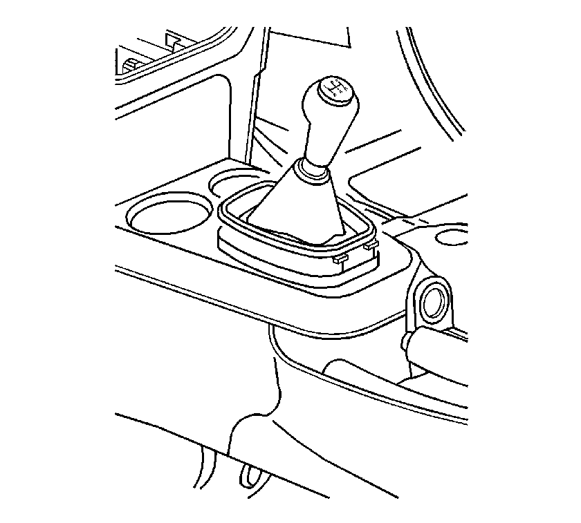
- For vehicles equipped with a manual transmission, unsnap the shift boot from the front console cupholder and lift the front console cupholder to disengage the retaining fasteners.
- Disconnect the accessory outlet connector.
- Remove the front console cupholder.
- Remove the electrical tape from the accessory outlet wiring harness. Two wires should now be exposed.
- Cut the orange wire 3 cm (1 1/16 in) from the connector and cut the black wire 11.5 cm (4 1/2 in) from the connector.
- Strip away 1 cm (3/8 in) material on all four exposed wire ends.
- Trim the wire on both ends of the capacitor so they are 3 cm (1 3/16 in) in length.
- Insert the orange wire from the connector into one end of a salmon colored Dura Seal™ splice sleeve and crimp the splice sleeve.
- Insert the black wire from the connector into one end of the other salmon colored splice sleeve. Then insert one wire end from the capacitor into the same side of the Dura Seal™ splice sleeve that the black wire is inserted in and crimp the splice sleeve.
- Insert the black wire from the harness into the other end of Dura Seal™ splice sleeve that contains the black wire and one wire from the capacitor and crimp the splice sleeve.
- Insert the orange wire from the wiring harness and the other wire end from the capacitor into the other end of the Dura Seal™ splice sleeve that contains the orange wire and the crimp sleeve.
- Seal the sleeve by applying heat using a heat gun, or equivalent, heating to 175°C (347°F) until glue flows around edges of the sleeve.
- Using electrical tape, re-wrap the harness. Make sure to cover the exposed wires of the capacitor.
- Reposition the accessory outlet wiring harness in the shifter console and reconnect the accessory outlet connector.
- For vehicles equipped with a manual transmission, slide the shift boot through the front console cupholder.
- Align the retaining fasteners on the front console cupholder with the console and push the front console cupholder to secure.
- For vehicles equipped with a manual transmission, snap the shift boot to the front console cupholder.
- For vehicle equipped with an automatic or Vti transmission, perform the following:
- Install the lighter fuse in the IBCM (fuse cavity F20).
| 2.1. | Apply the brake and shift the transmission into neutral. |
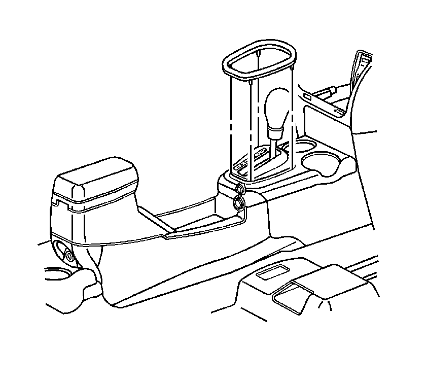
| 2.2. | Remove the console shift lever bezel by carefully lifting up around the outside edge. |
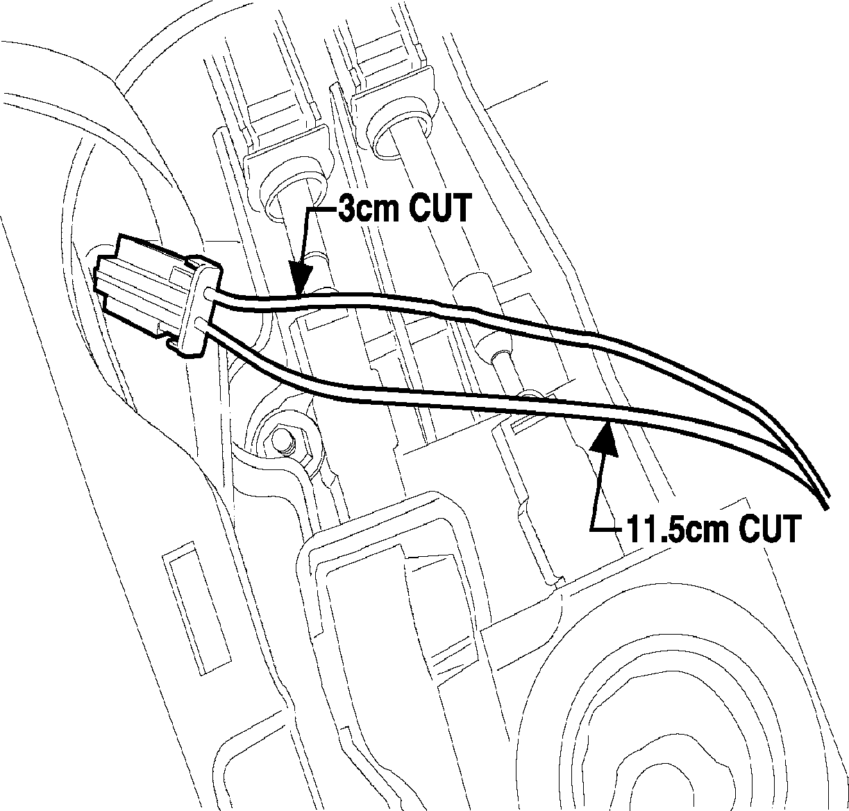
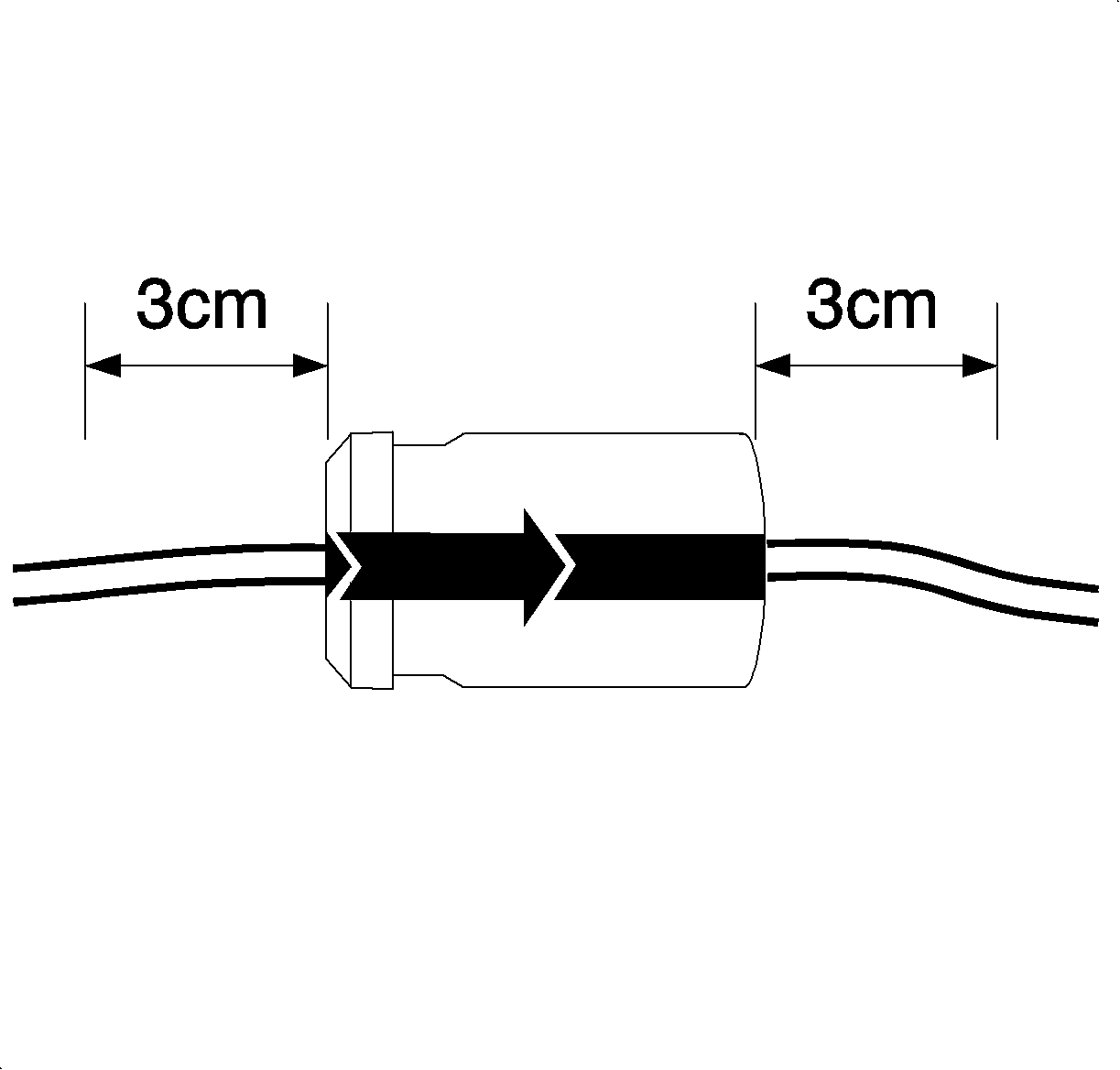
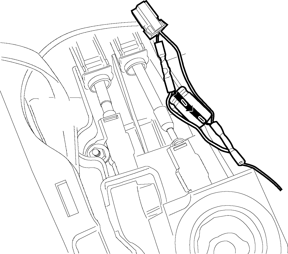
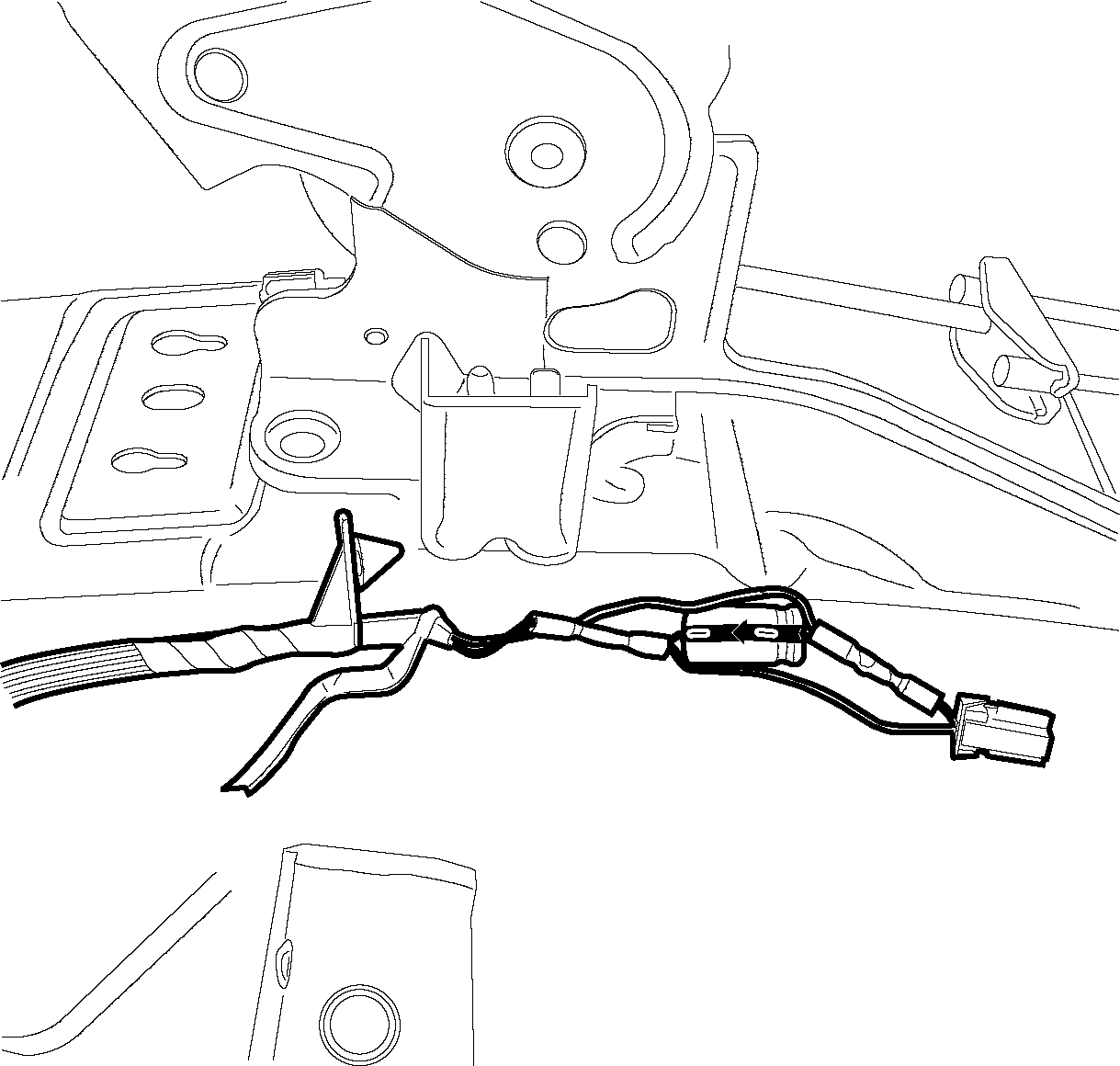
Important: When installing the capacitor, make sure the arrows on the capacitor point to the ground wire. If there are no arrows look for "+" or "-" symbol on the capacitor. Make sure the capacitor lead nearest the "-" symbol goes to the ground wire (black). Make sure the capacitor lead nearest the "+" symbol goes to the power wire (orange).
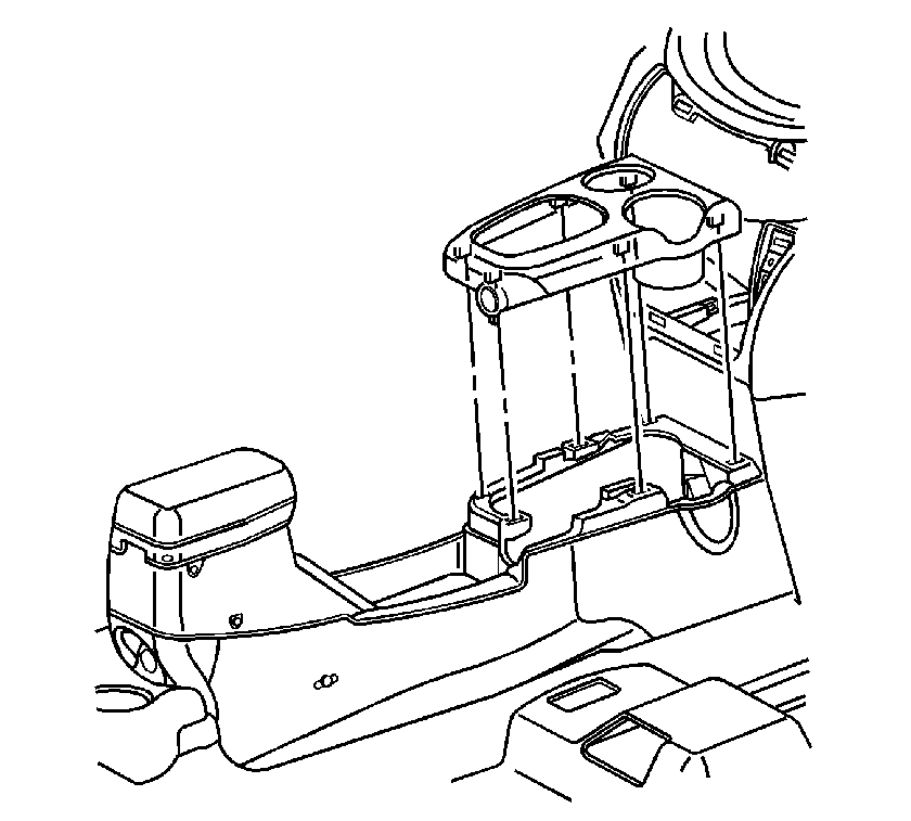

| 20.1. | Align the fingers on the shift lever bezel with the slots on the shifter base. Push the console shift lever bezel to secure. |
| 20.2. | Shift the transmission into Park. |
Rear Accessory Outlet Repair
- Remove the PWR OUTLET fuse from the IBCM (fuse cavity F22).
- Raise the park brake lever.
- Unsnap the park brake boot from the console.
- For vehicles with a center armrest, remove the two retaining screws.
- Lift up on the rear of the console compartment to release the retaining fasteners.
- Lift the console compartment and push the park brake boot through the opening in the compartment.
- Slide the console compartment over the park brake lever.
- Disconnect the rear accessory outlet connector.
- Disconnect the wiring accessory outlet wiring harness rosebud connector at the parking brake bracket for easier access to the wiring harness.
- Remove 15 cm (5 7/8 in) of tape, starting at the rosebud connector and working forward towards the Sensing Diagnostic Module (SDM).
- Cut the yellow wire 5 cm (2 in) from the rosebud connector and cut the black wire 13.5 cm (5 3/8 in) from the rosebud connector.
- Strip away 1 cm (3/8 in) of material on all four exposed wire ends.
- Trim the wires on both ends of the capacitor so they are 3 cm (1 3/16 in) in length.
- Insert the yellow wire from the connector into one end of a salmon colored Dura Seal™splice sleeve and crimp the splice sleeve.
- Insert the black wire from the connector into one end of the other salmon colored Dura Seal™splice sleeve. Then insert one wire end from the capacitor into the same side of the Dura Seal™splice sleeve that the black wire is inserted in and crimp the splice sleeve.
- Insert the black wire from harness into the other end of Dura Seal™ splice sleeve that contains the black wire and one wire from the capacitor and crimp the splice sleeve.
- Insert the yellow wire from the wiring harness and the other wire end of the capacitor into the other end of the Dura Seal™ splice sleeve that contains the yellow wire and crimp the splice sleeve.
- Seal the sleeve by applying heat using a heat gun, or equivalent, heating to 175°C (347°F) until glue flows around edges of the sleeve.
- Using electrical tape, re-wrap the harness. Make sure to cover the exposed wires of the capacitor.
- Reinstall the wiring harness rosebud connector into the parking brake bracket.
- Install the connector into the rear accessory outlet.
- Slide the console compartment over the park brake lever.
- Pull the park brake boot through the opening in the console compartment.
- Align the retaining fasteners with the console and push to secure.
- If the vehicle is equipped with a center armrest, install both console compartment screws.
- Snap the brake boot to the console.
- Install the PWR OUTLET fuse in the IBCM (fuse cavity F22).
- Verify that the concern is gone by starting the vehicle and reinstalling the charger and the device to be charged in the front and rear accessory outlet while monitoring the DRLs.
- Install a scan tool and clear any DTCs that may be set.
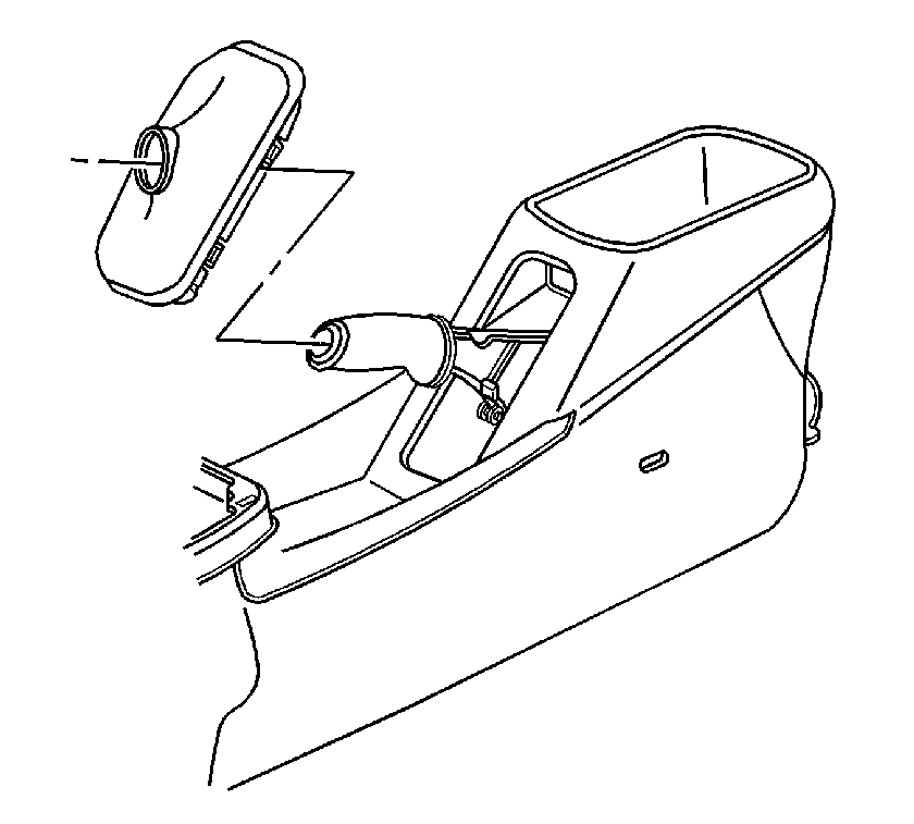
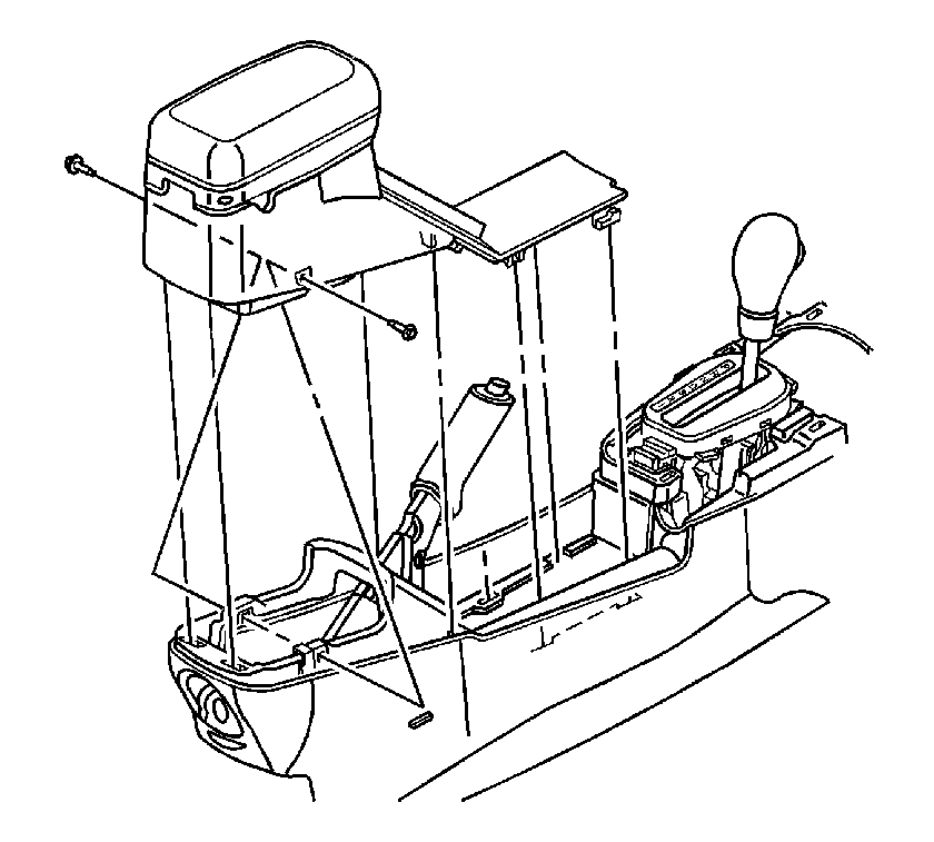
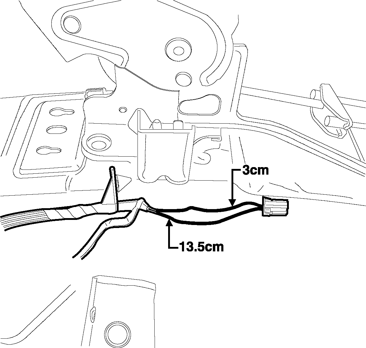

Important: When installing the capacitor, make sure the arrows on the capacitor point to the ground wire. If there are no arrows look for "+" or "-" symbol on the capacitor. Make sure the capacitor lead nearest the "-" symbol goes to the ground wire (black). Make sure the capacitor lead nearest the "+" symbol goes to the power wire (yellow).


Tighten
Tighten the screws to 2.5 N·m(22 lb in).
Parts Information
Part Number | Description | Qty |
|---|---|---|
10395194 | Capacitor | 2 |
12089189 | Salmon Splice Sleeve | 4 |
Warranty Information
To receive credit for any repairs during the warranty coverage period, submit a claim through the Saturn Dealer System for N6116 (Wiring and/or Connector, Cigarette Lighter - Replace).
