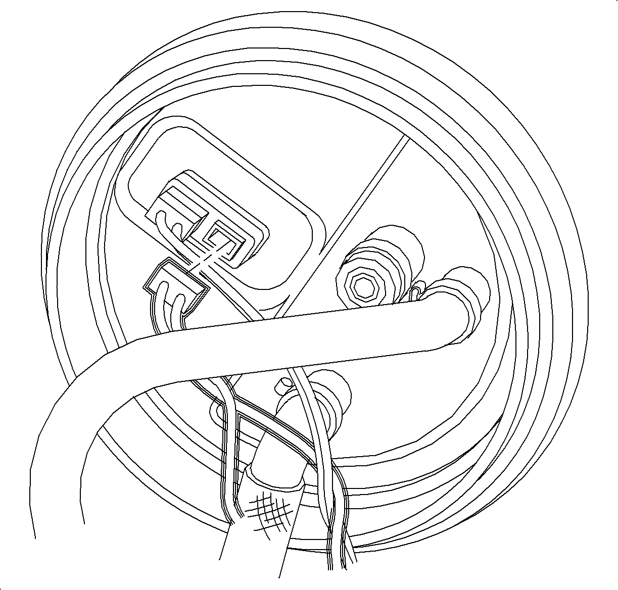
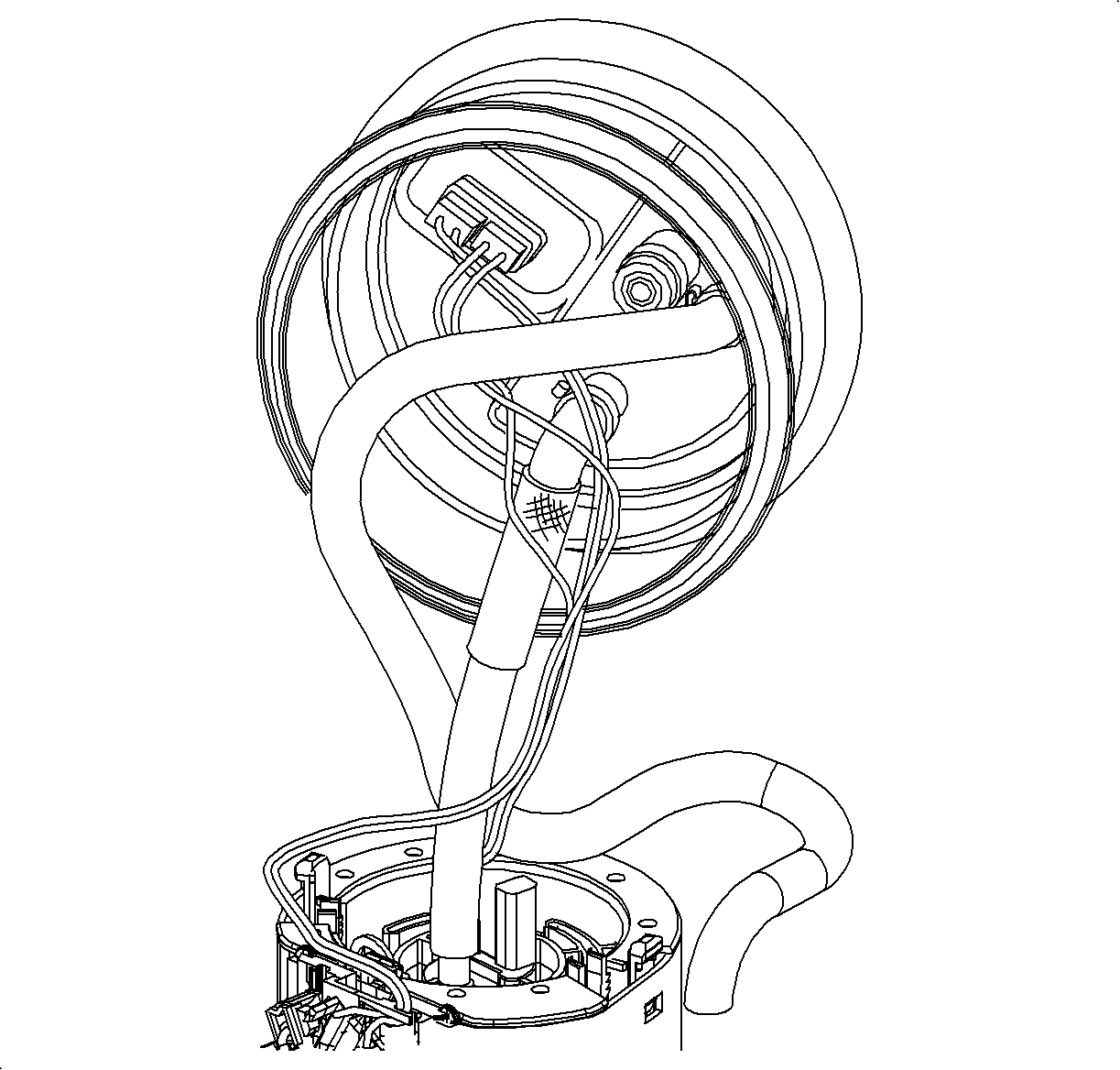
For 1990-2009 cars only
Tools Required
J 43827 Fuel Sending Unit Wrench
Removal Procedure
- Remove fuel tank. (Refer to "Fuel Tank Removal" procedure in this section of the service manual.)
- Disconnect fuel lines from fuel pump module cover.
- Use the J 43827 and remove the fuel pump module retaining ring. A 1/2 in. breaker bar (approximately 18 inches long) will easily loosen and remove the lock ring.
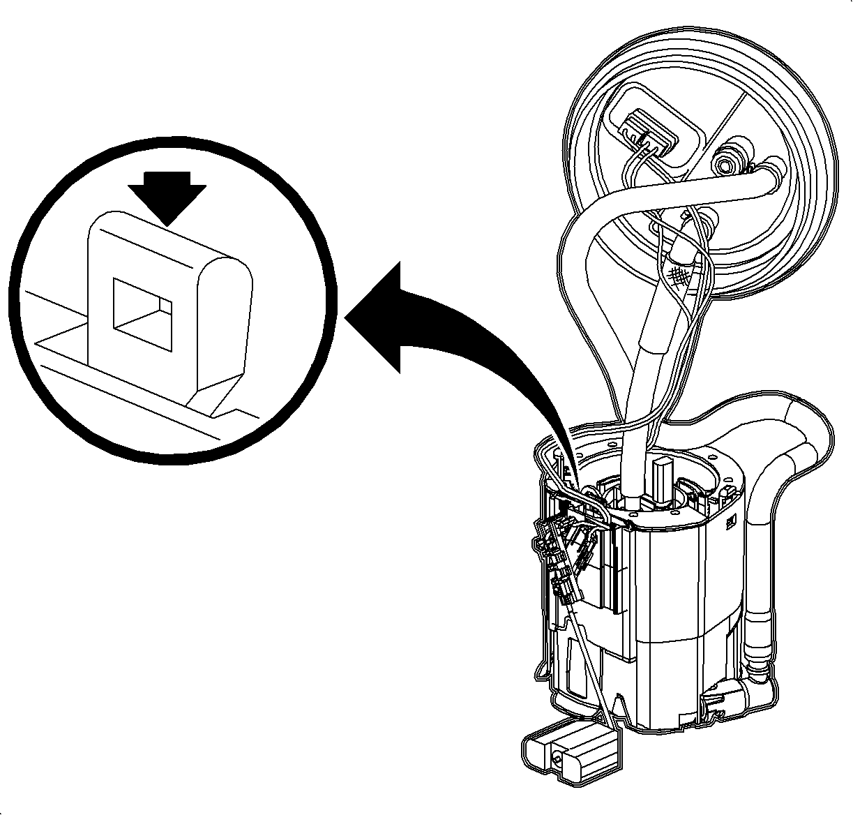
- To prevent bending of the sending unit float arm remove the sending unit first by pulling the retaining clip toward float arm and lift upward.
- Carfeully lift fuel pump straight up from fuel tank. To disengage fuel pump from fuel pump housing (4) clips must be disenabled at the same time.
- Discard fuel pump module to tank seal.
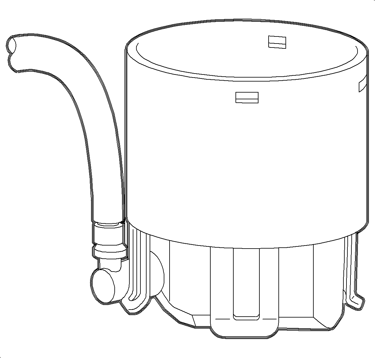
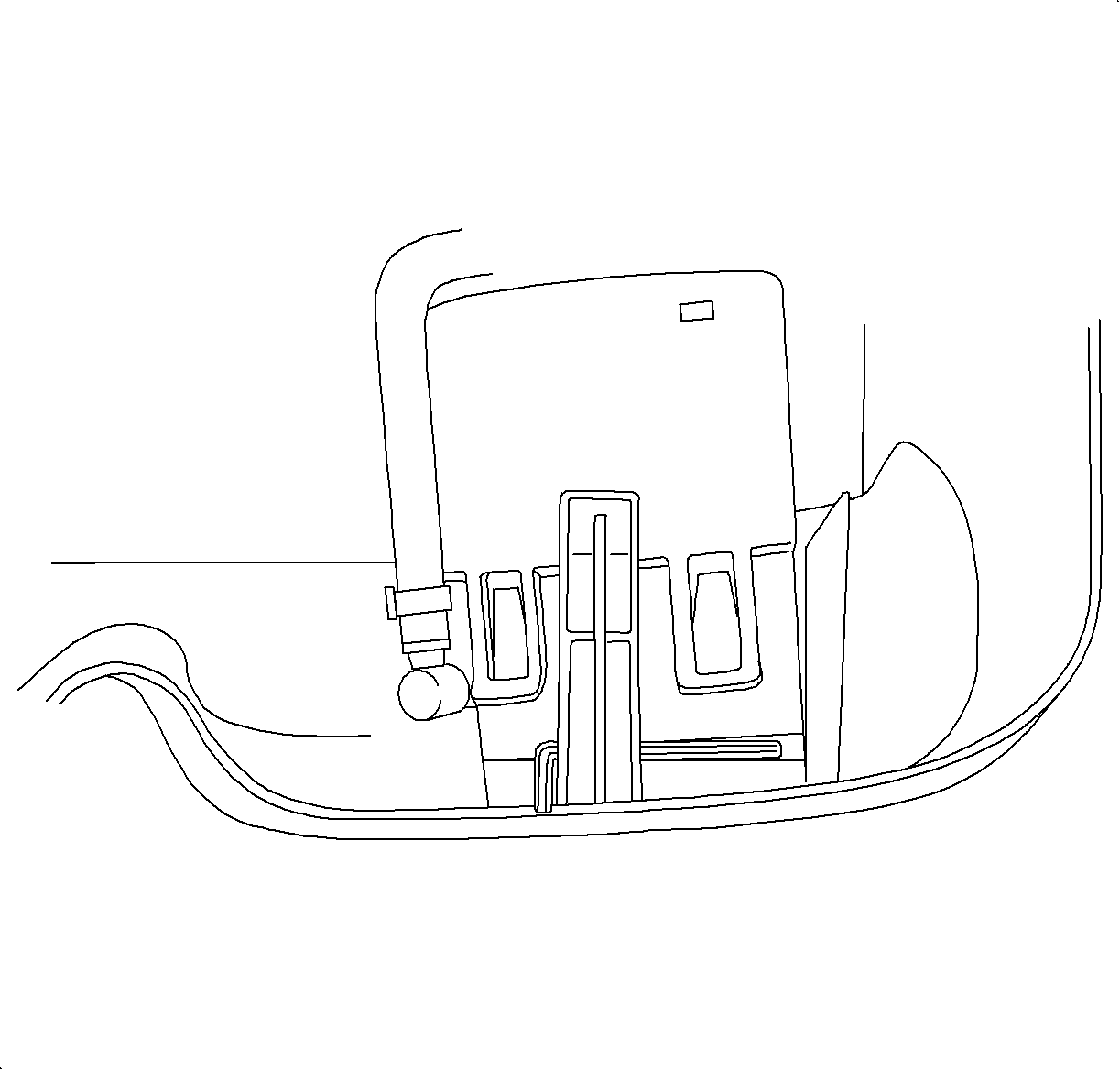
- Remove fuel pump housing by releasing the four retaining clips. The retaining clips hold fuel pump housing to fuel pump housing bracket (mounted in bottom of tank).
- Disengage clip closest to the pump (where fuel return line attaches to fuel pump housing) by inserting a small flat blade screwdriver between the clip (on the housing) and the mounting bracket. Leave screwdriver wedged in place to prevent clip from reattaching as the other clips are being disenabled.
- Disengage the clip closest to the one disengaged in previous step (toward rear of tank). Use a second small flat blade screwdriver to disenable this clip.
- Stick one of the screwdrivers between the fuel pump housing and base of the fuel tank to prevent clips (previous steps) from re-engaging. Remove second screwdriver from fuel tank.
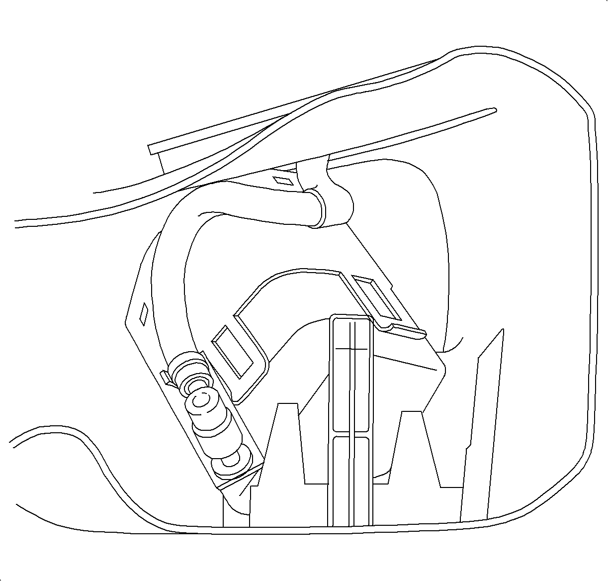
- The next clip to be disengaged is at the rear most position. To disengage this clip tilt housing toward jet pump while releasing this clip.
- Once these clips have been disengaged push module (or roll the module) in the direction of the remaining clip that is engaged. This will force clip to disengage.
- Remove housing from tank.
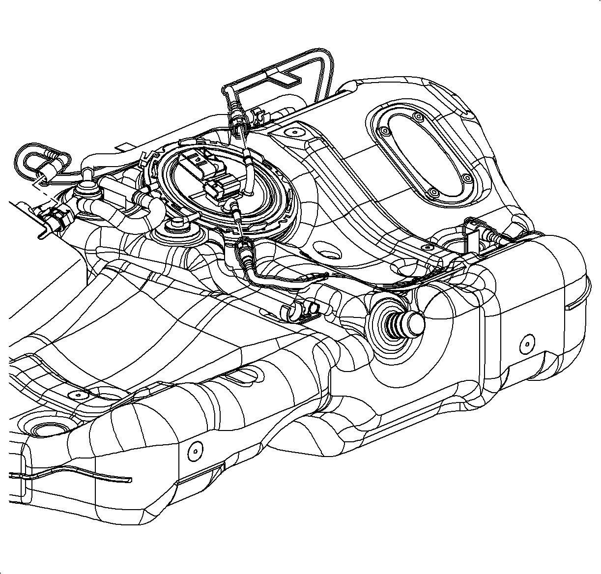
Notice: Clean all fuel pipe and hose connections and surrounding areas before disassembling to avoid possible contamination of the fuel system. Spray the fuel pump module cam-lock ring tang with penetrating oil prior to attempting removal.
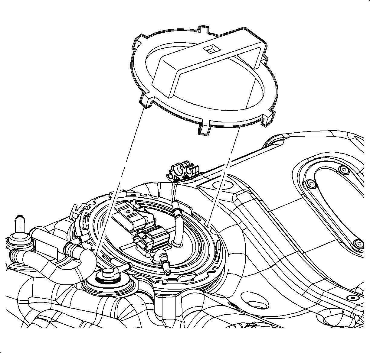
Notice: To prevent retainer damage, do not attempt to remove the retainer with a 12 in. or shorter ratchet/breaker bar.
Important: Always replace fuel pump module to tank seal (O-ring) whenever assembly is removed.
Important: Inspect the fuel tank for metal chips/debris. Remove all contaminants and replace in-line fuel filter before installing a new fuel pump assembly when debris is present.
Installation Procedure
- Install new fuel pump and housing straight down into fuel pump housing bracket. The jet pump needs to be toward front of tank on drivers side. Make sure all clips engage.
- Install fuel level sender into fuel pump housing and connect its connector to fuel pump cover.
- Insert new fuel pump to fuel tank seal.
- UseJ 43827 to install fuel pump cover lock ring. (The bumps on the lock ring need to be facing away from the tank.)
- Connect fuel lines and wiring harness.
- Install fuel tank. (Refer to "Fuel Tank Installation" procedure in this service manual.)

