Power Mirror
The power mirror system provides the ability to electrically position the driver and passenger side mirror. The system consists of a switch mounted on the driver's side door handle, and 2 reversible electric motors for each mirror.
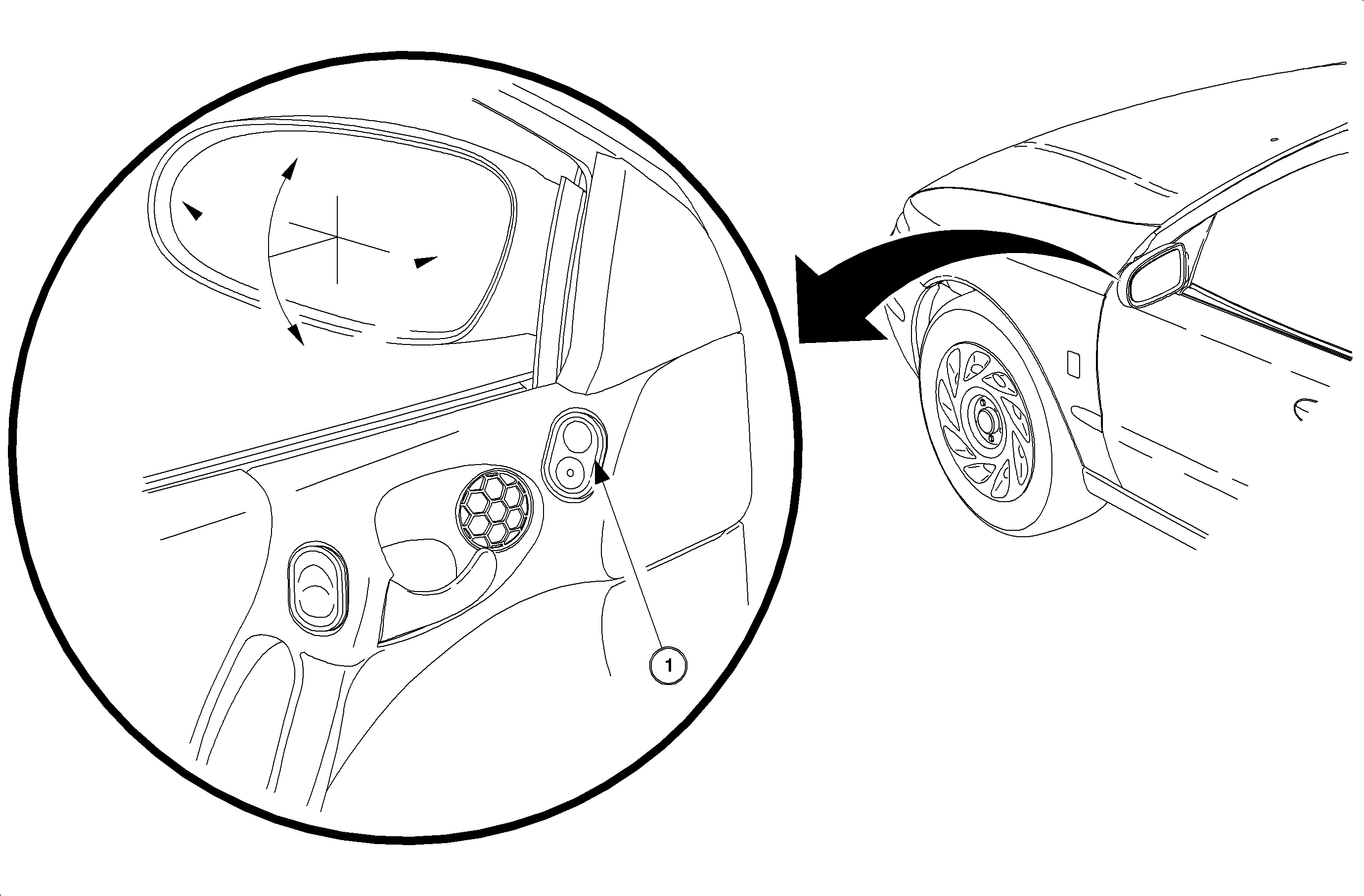
Power Mirror Motors
Each mirror has 2 reversible electric motors: one to adjust the mirror view up and down, and the other to adjust right or left.
Power Mirror Switch
The power mirror switch controls the right and left mirror position. The mirror select switch (rocker switch) allows control of the right or left mirror. The mirror adjustment switch (pad switch) allows control of the mirror position: UP, DOWN, RIGHT, or LEFT.
With the mirror select switch is in the LEFT mirror position, the circuit operation is as follows:
If the mirror adjustment switch is pressed in the UP position, battery voltage from circuit 743 is applied to circuit 881 to the up/down mirror motor in the left mirror. The mirror switch supplies a ground path for circuit 82 through the closed contacts to circuit 550, and the mirror moves up. When the mirror adjustment switch is pressed in the DOWN position, battery voltage from circuit 743 is applied through to circuit 82 to the up/down mirror motor in the left mirror. The mirror switch supplies a ground path for circuit 881 through the closed contacts to circuit 550, and the mirror moves down.
When the mirror adjustment switch is moved to the RIGHT position, battery voltage from circuit 743 is applied through to circuit 889 to the right/left mirror motor in the left mirror. The mirror switch supplies a ground path for circuit 82 through the closed contacts to circuit 550, and the mirror moves right. When the mirror adjustment switch is moved to the LEFT position, battery voltage from circuit 743 is applied through to circuit 82 to the right/left mirror motor in the left mirror. The mirror switch supplies a ground path for circuit 889 through the closed contacts to circuit 550, and the mirror moves left. The controls of the mirror position switch are the same for the right and left position of the mirror select switch.
With the mirror select switch in the RIGHT mirror position, the circuit operation is as follows:
If the mirror adjustment switch is pressed in the UP position, battery voltage form circuit 743 is applied to circuit 81 to the up/down mirror motor in the left mirror. The mirror switch supplies a ground path for circuit 82 through the closed contacts to circuit 550, and the mirror moves up. When the mirror adjustment switch is pressed in the DOWN position, battery voltage from circuit 743 is applied through to circuit 82 to the up/down mirror motor in the right mirror. The mirror switch supplies a ground path for circuit 81 through the closed contacts to circuit 550, and the mirror moves down.
When the mirror adjustment switch is moved to the RIGHT position, battery voltage from circuit 743 is applied through to circuit 89 to the right/left mirror motor in the right mirror. The mirror switch supplies a ground path for circuit 82 through the closed contacts to circuit 550, and the mirror moves right. When the mirror adjustment switch is moved to the LEFT position, battery voltage from circuit 743 is applied through to circuit 82 to the right/left mirror motor in the right mirror. The mirror switch supplies a ground path for circuit 89 through closed contacts to circuit 550, and the mirror moves left. The controls of the mirror position switch are the same for the right and left position of the mirror select switch.
