Ignition Key Binds or Does Not Turn Out of the LOCK Position

| Subject: | Ignition Key Binds or Does Not Turn Out of the LOCK Position -- Replace Lock Cylinder, Tumblers and Springs |
| Models: | 2000-2001 Saturn L-Series and S-Series Vehicles |
Condition:
Some customers may comment that the ignition key will not turn out of the LOCK position.
Cause:
This condition is caused by one or more of the ignition cylinder tumblers binding in the ignition cylinder tumbler body.
Correction:
Refer to the procedure detailed in this bulletin to replace the ignition lock cylinder, tumblers, and tumbler springs.
Important: This bulletin contains separate service procedures for L-Series and S-Series vehicles.
| • | For L-Series vehicles, refer to pages 2-8 in this bulletin. |
| • | For S-Series vehicles, refer to pages 9-15 in this bulletin. |
L-Series Procedure:
- Disconnect the negative battery cable.
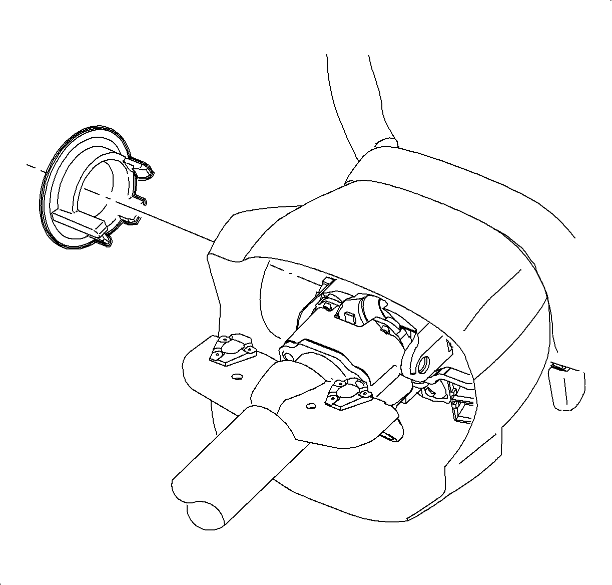
- Remove the lock cylinder bezel from the steering column shroud by carefully prying with a thin bladed screwdriver.
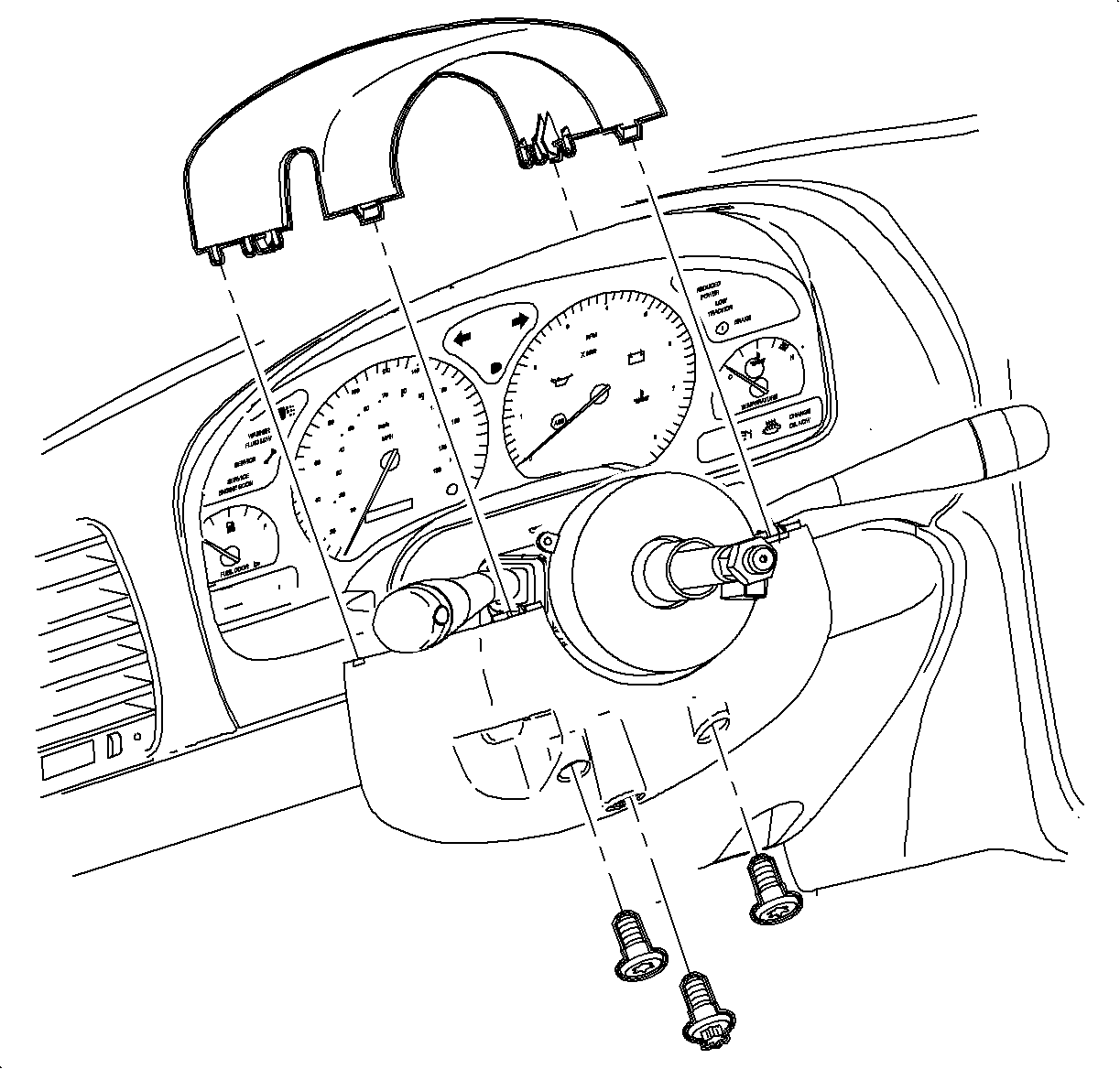
- Remove the steering column upper shroud panel.
- Insert the key into the ignition lock cylinder and rotate to the START position.
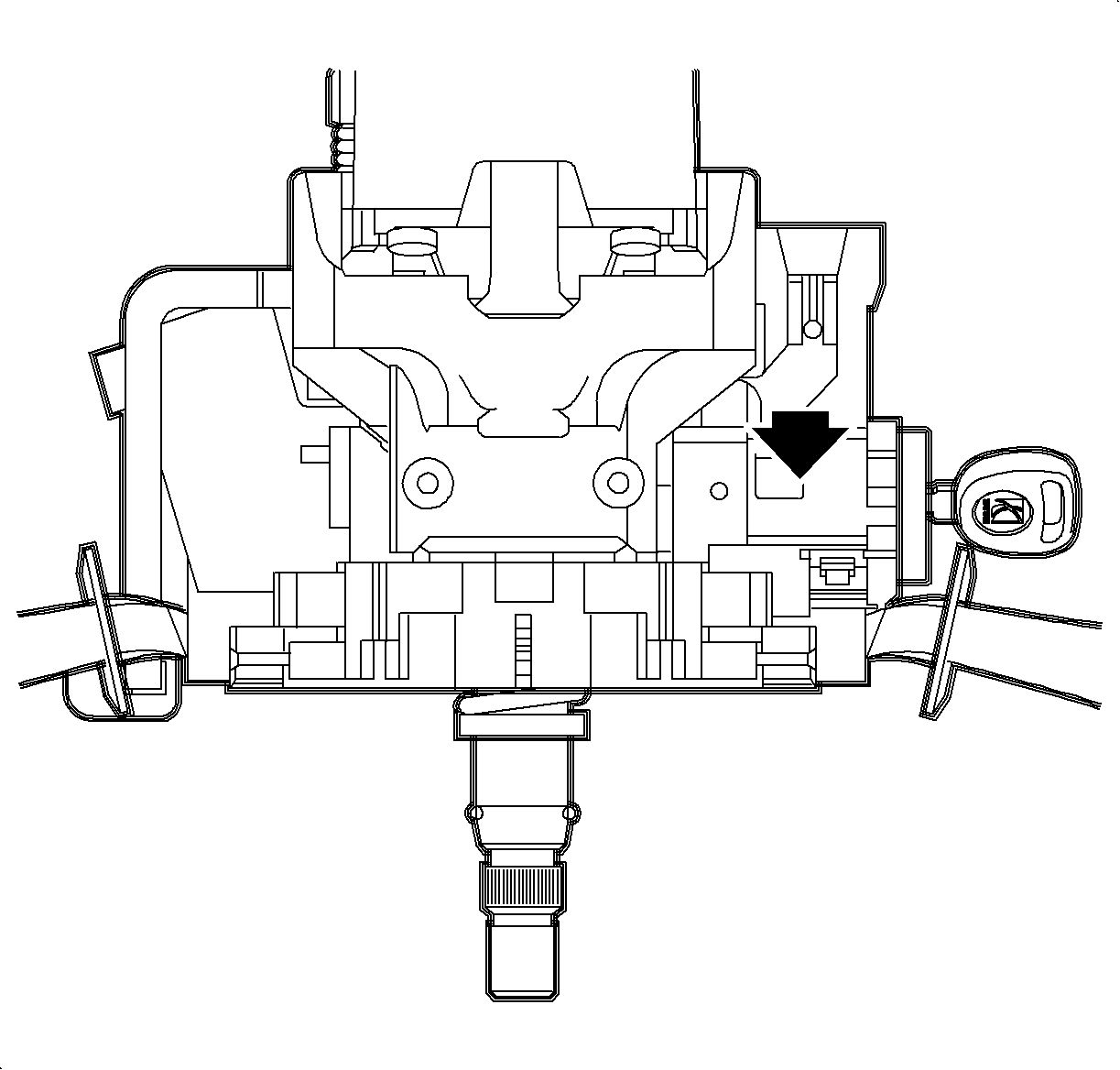
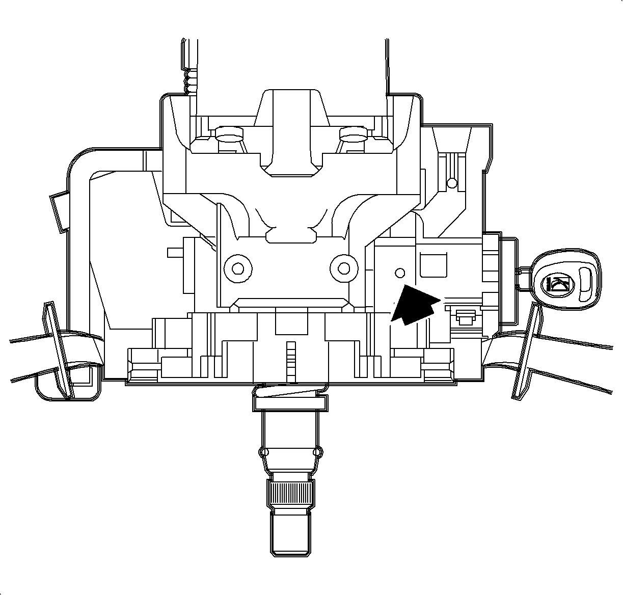
- Using a light hammer and brass drift, tap lightly on the ignition housing assembly at the location indicated in the illustration, while trying to turn the ignition key.
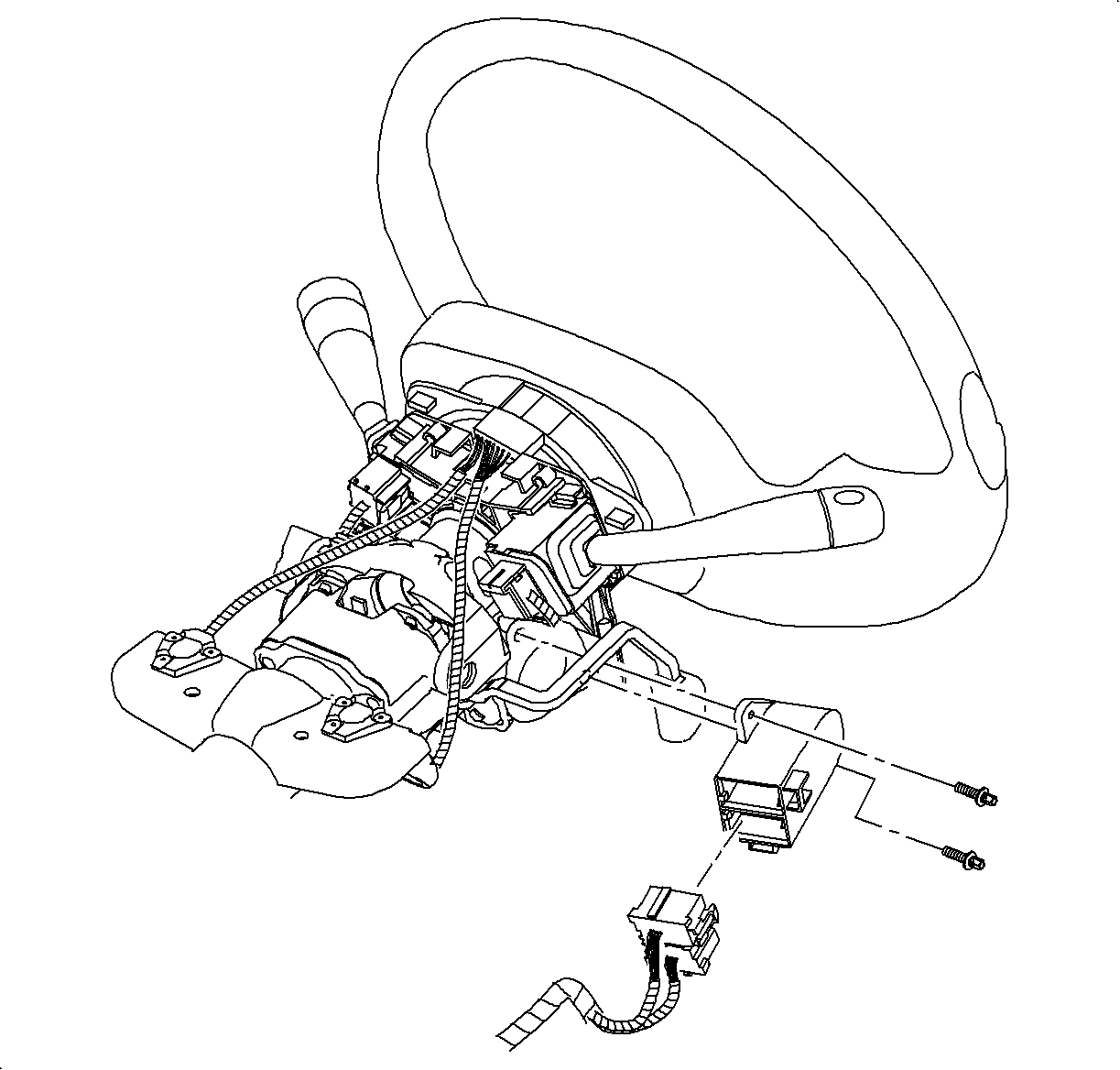
- Disconnect the ignition switch connector and remove the ignition switch from the ignition housing.
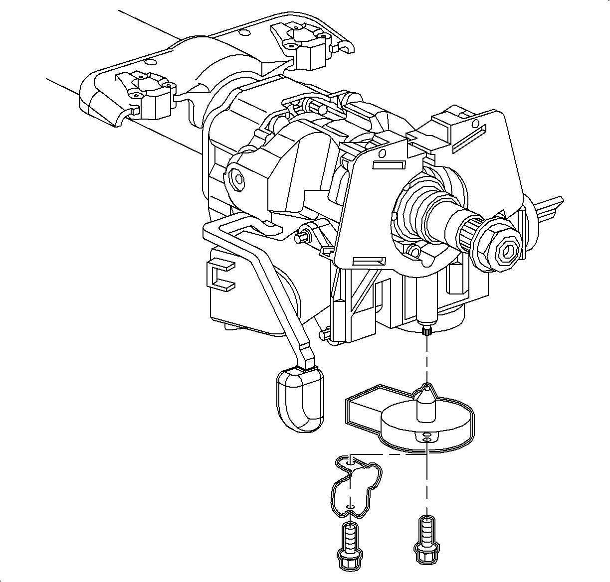
- Remove the park lock solenoid.
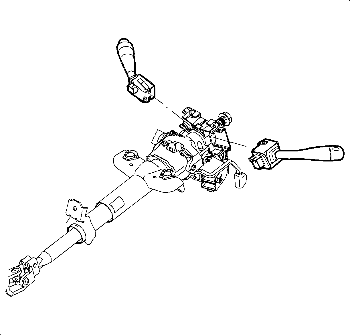
- Remove the turn signal/headlamp lever, windshield washer lever, and Passlock sensor connector.
- Remove the ignition housing shear bolts.
- Remove the ignition housing assembly from the steering column.
- Use new shear bolts to install the ignition housing assembly on the steering column.
- Install the turn signal/headlamp lever, windshield washer lever, and Passlock sensor connector.
- Install the park lock solenoid.
- Install the ignition switch and reconnect the ignition switch connector.
- If the ignition housing did not require placement, depress the locking button on the top of the ignition module assembly with a thin pick-type tool. Slide the lock cylinder assembly from the ignition module.
- Discard the old lock cylinder assembly. New lock cylinder and components must be used. Refer to Parts Requirements section in this bulletin for specific parts requirements.
- Replace the ignition cylinder, ignition cylinder tumblers and tumbler springs.
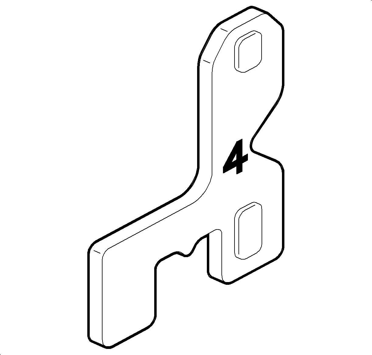
- Select the correct tumblers for the desired code by the number stamped on the tumbler.
- Install the tumbler and tumbler springs.
- Place a new tumbler retainer plate into position and stake into the ignition lock cylinder using the lock cylinder holding fixture and staking tool J 43877.
- To check the coding of the cylinder, insert the key. If the coding is correct, the sidebar will be flush with the cylinder with the key inserted.
- For assembly, oil the lock set with a light oil or graphite lubricant.
- Insert the ignition key into the ignition lock cylinder and install the cylinder into the ignition housing.
- Install the steering column upper shroud.
- Install the lock cylinder bezel.
- Connect the negative battery cable.
- Verify the proper function of the ignition lock cylinder.
| • | If the ignition lock cylinder can be rotated to the START position, continue to step 15. |
| • | If the ignition lock cylinder cannot be rotated to the START position, continue with the next step. |
| • | If the ignition key turns, proceed to step 15. |
| • | If the ignition key does not turn, replace the ignition housing assembly by continuing with the next step. |
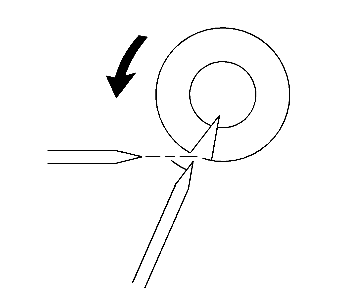
| 9.1. | Use a light hammer and chisel to bite into the shear bolt head at a position offset from its center. |
| 9.2. | Tap the chisel to rotate the bolt and loosen it. |
| 9.3. | Repeat until the bolt is loose enough to remove. |
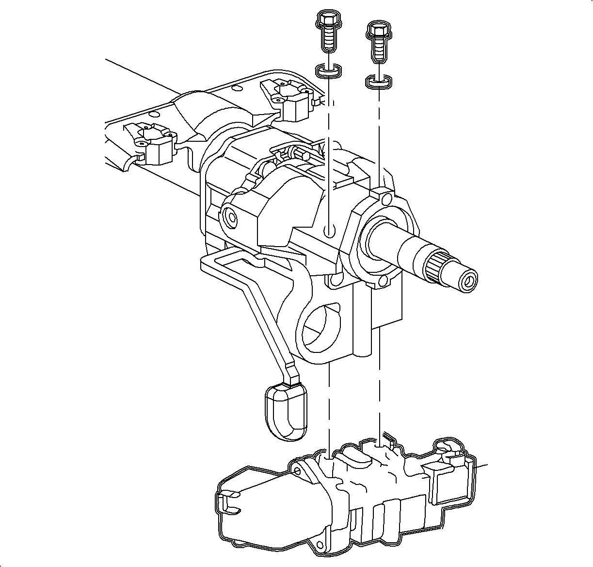
Tighten
Tighten the shear bolts until the heads break off.


Tighten
Tighten the park lock solenoid screws to 1.5 N·m (14 lb in).
Tighten
Tighten the ignition switch fasteners to 1.5 N·m (14 lb in).
Important: The new lock cylinder must be coded. Follow steps 17-22 for the coding procedure.
The ignition lock cylinder reads key cut positions 2-10.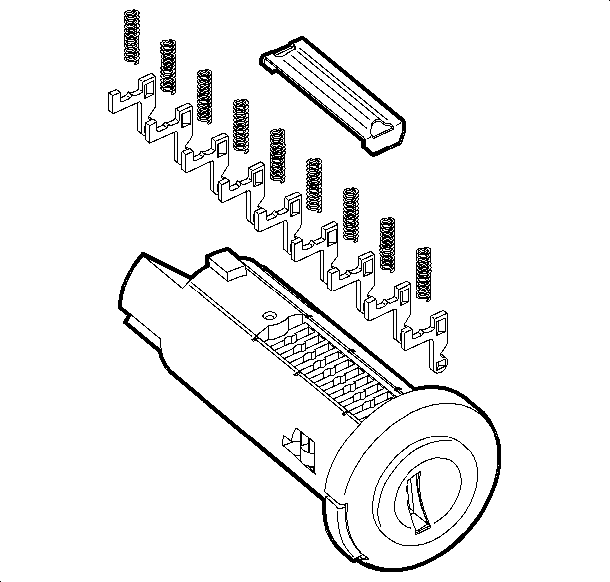

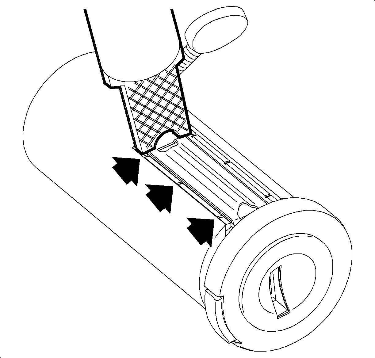
| • | Clamp the staking tool holding fixture into a vise. |
| • | Place the lock cylinder into the staking tool holding fixture. |
| • | Tighten the retaining screw. |
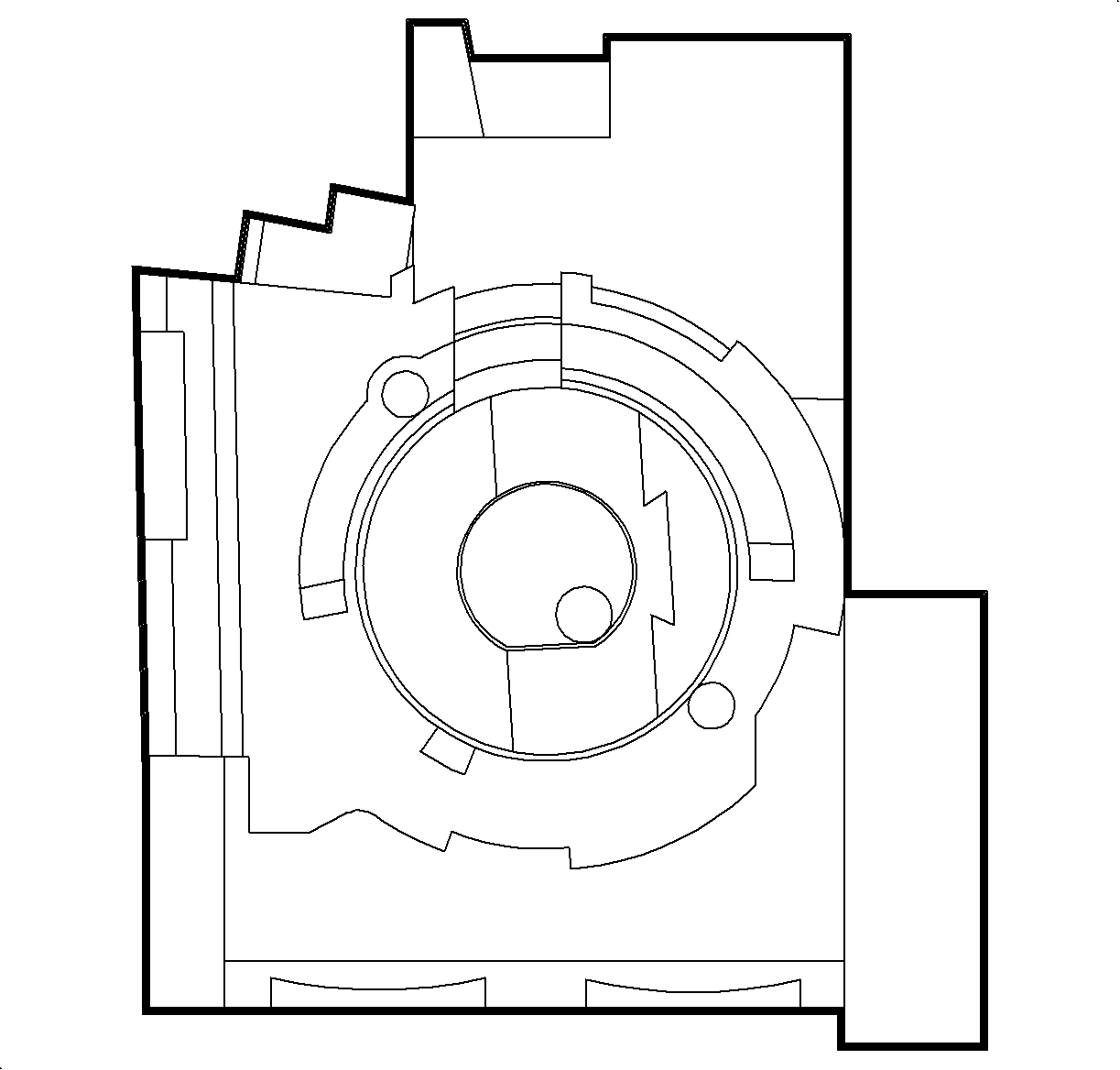
| • | Stake the retainer plate with a punch at the locations shown in the illustration. |
Important: The actuator blade within the ignition module housing must be in the RUN position to install the lock cylinder assembly. If rotated, replace it to the RUN position using needle nose pliers.

Tighten
Tighten the steering column cover attaching fasteners to 4 N·m
(35 lb in).

Tighten
Tighten the battery terminal blot to 17 N·m (13 lb ft).
S-Series Procedure:
Important: The important statement at the beginning of the Ignition Lock Cylinder removal procedure on page 188 in the 2000/2001 Saturn S-Series Body/Electrical Volume II Service Manual is incorrect. Please cross out the important on that page and write in the following important statement.
Important: When replacing the ignition lock cylinder only, the Passlock relearn procedure is not required.
- Disconnect the negative battery cable.
- Remove the lock cylinder bezel from the steering column shroud by carefully prying with a thin bladed screwdriver.
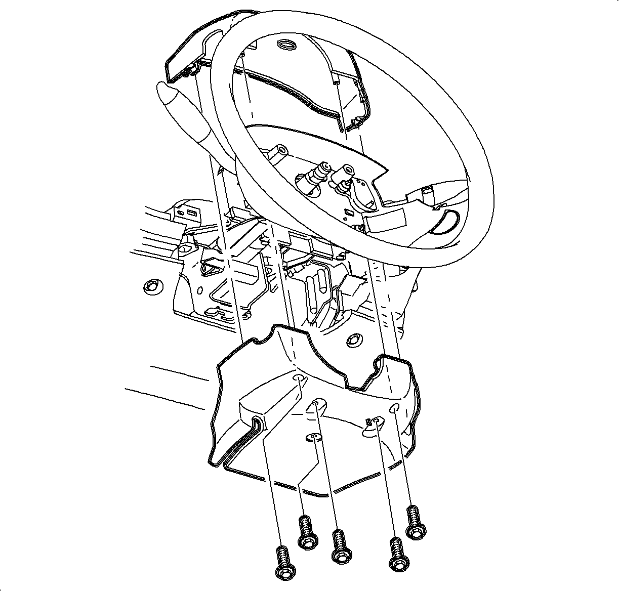
- Remove the shroud fasteners and remove the steering column upper and lower shroud panels.
- Insert the key into the lock cylinder and rotate it to the RUN position.
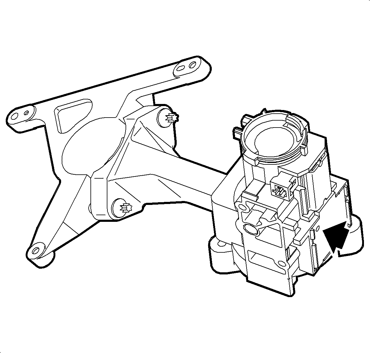
- Using a light hammer and brass drift, tap lightly on the ignition housing assembly at the location indicated in the illustration, while trying to turn the ignition key.
- Disable the SIR system. Refer to Disabling Frontal Inflators procedure in the 2000/2001 Saturn S-Series Body/Electrical Volume II Service Manual.
- Remove the SIR Coil assembly. refer to Roll Connector Assembly removal procedure in the 2000/2001 Saturn S-Series Body/Electrical Volume II Service Manual.
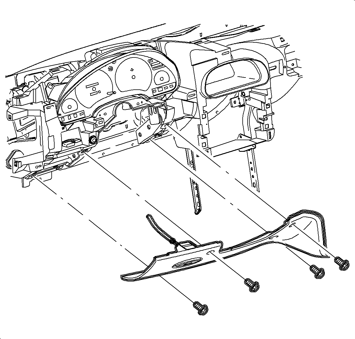
- Pull the steering column filler panel assembly forward and set aside.
- Disconnect the cable from the filler panel. Pull the hood release handle forward. Feed the cable under the hood release handle and slide the pin out. Remove the steering column filler panel.
- Remove the connector position assurance (CPA) retainer and disconnect the connectors from the lever control switch.
- With the SIR system disabled, remove the lever control switch.
- Disconnect the ignition switch electrical connector at the right steering column upper support bracket.
- On vehicles with automatic transaxles, disconnect the park lock cable from the ignition module.
- Disconnect the Passlock sensor connector from the ignition module.
- Remove the ignition module/Passlock shear bolts.
- Remove the ignition module/Passlock sensor from the steering column.
- Use new shear bolts to install the ignition module/Passlock sensor on the steering column.
- Install the harness clamps on the steering column.
- Connect the Passlock sensor connector to the ignition module.
- On vehicles with automatic transaxles, connect the park lock cable to the ignition module.
- Reconnect the Passlock sensor connector to the ignition module.
- Install the lever control switch by fitting it into the bottom locating holes on the ignition module.
- Connect the connectors to the lever control switch. Install the connector position assurance (CPA) retainers.
- Connect the ignition switch electrical connector at the right steering column support bracket bolt.
- Pull the hood release handle forward. Feed the cable under the hood release handle and slide the pin in. Connect the cable to the filler panel.
- Install the steering column filler panel and data link connector.
- Install and tighten the screws.
- Install the SIR coil assembly. Refer to Roll Connector Assembly installation procedure in the 2000/2001 S-Series Restraints Service Manual
- Enable the SIR system. Refer to Enabling Frontal Inflators in the 2000/2001 Saturn S-Series Body/Electrical Volume II Service Manual
- Rotate the ignition cylinder back to the ACC position.
- If the ignition module/Passlock sensor did not require replacement, depress the locking button on the top of the ignition module assembly with a thin pick-type tool. Slide the lock cylinder assembly from the ignition module.
- Discard the old lock cylinder assembly; new lock cylinder and components must be used. Refer to PARTS REQUIREMENTS section in this bulletin for specific parts information.
- Replace the ignition cylinder tumblers and tumbler springs.
- Select the correct tumblers for the desired code by the number stamped on the tumbler.
- Install the tumblers and tumbler springs.
- Place a new tumbler retainer plate into position and stake it into the ignition lock cylinder using the Lock Cylinder Holding Fixture and Staking Tool J 43877.
- To check the coding of the cylinder, insert the key. If the coding is correct, the sidebar will be flush with the cylinder with the key inserted.
- For assembly, oil the lock set with a light oil or graphite lubricant.
- Insert the ignition key into the ignition lock cylinder and install it into the ignition module.
- Install the steering column upper and lower shroud panels and shroud fasteners.
- Install the lock cylinder bezel.
- Connect the negative battery cable.
- Verify proper function of the ignition lock cylinder.
| • | If the ignition lock cylinder can be rotated to the RUN position, continue to step 30. |
| • | If the ignition lock cylinder cannot be rotated to the RUN position, continue with the next step. |
| • | If the ignition key turns, proceed to step 30. |
| • | If the ignition key does not turn, replace the ignition module/Passlock sensor by continuing with the next step. |
Important: If the ignition module/Passlock sensor is replaced, the Passlock relearn procedure must be performed.


| 15.1. | Use a light hammer and chisel to bite into the shear bolt head at a position offset from its center. |
| 15.2. | Tap the chisel to rotate the bolt and loosen it. |
| 15.3. | Repeat until the bolt is loose enough to remove. |
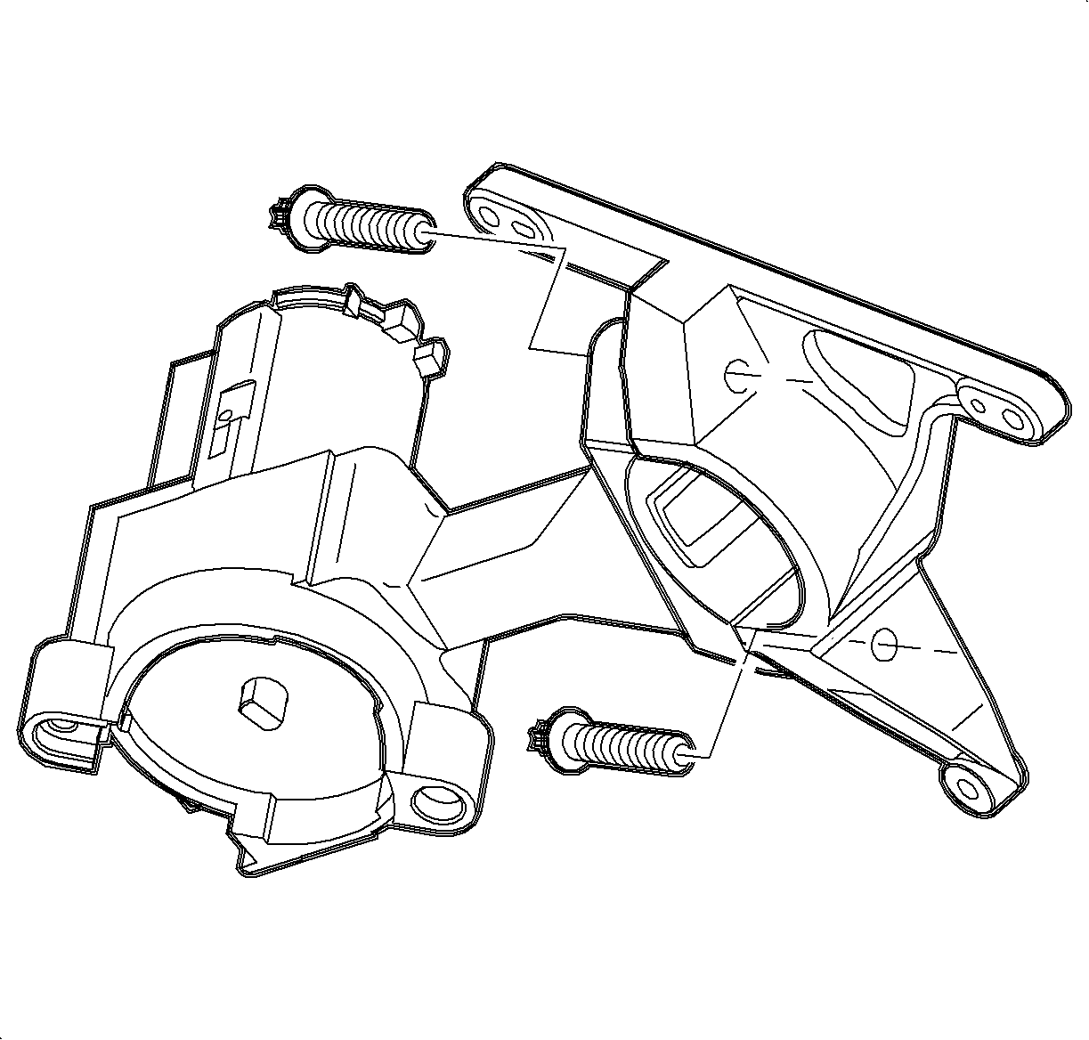
Tighten
Tighten the shear bolts until the heads break off.

Tighten
Tighten the steering column filler panel screws to 2.2 N·m (19 lb in).
Important: The new lock cylinder must be coded. Follow steps 32-37 for the coding procedure.
The ignition lock cylinder reads key cut positions 2-10.


Important: Make sure the ignition cylinder housing side bar is in the correct orientation before attempting to insert the tumblers.

| • | Clamp the staking tool holding fixture into a vise. |
| • | Place the lock cylinder into the staking tool holding fixture. |
| • | Tighten the retaining screw. |
| • | Stake the retainer plate with a punch at the locations shown in the illustration. |
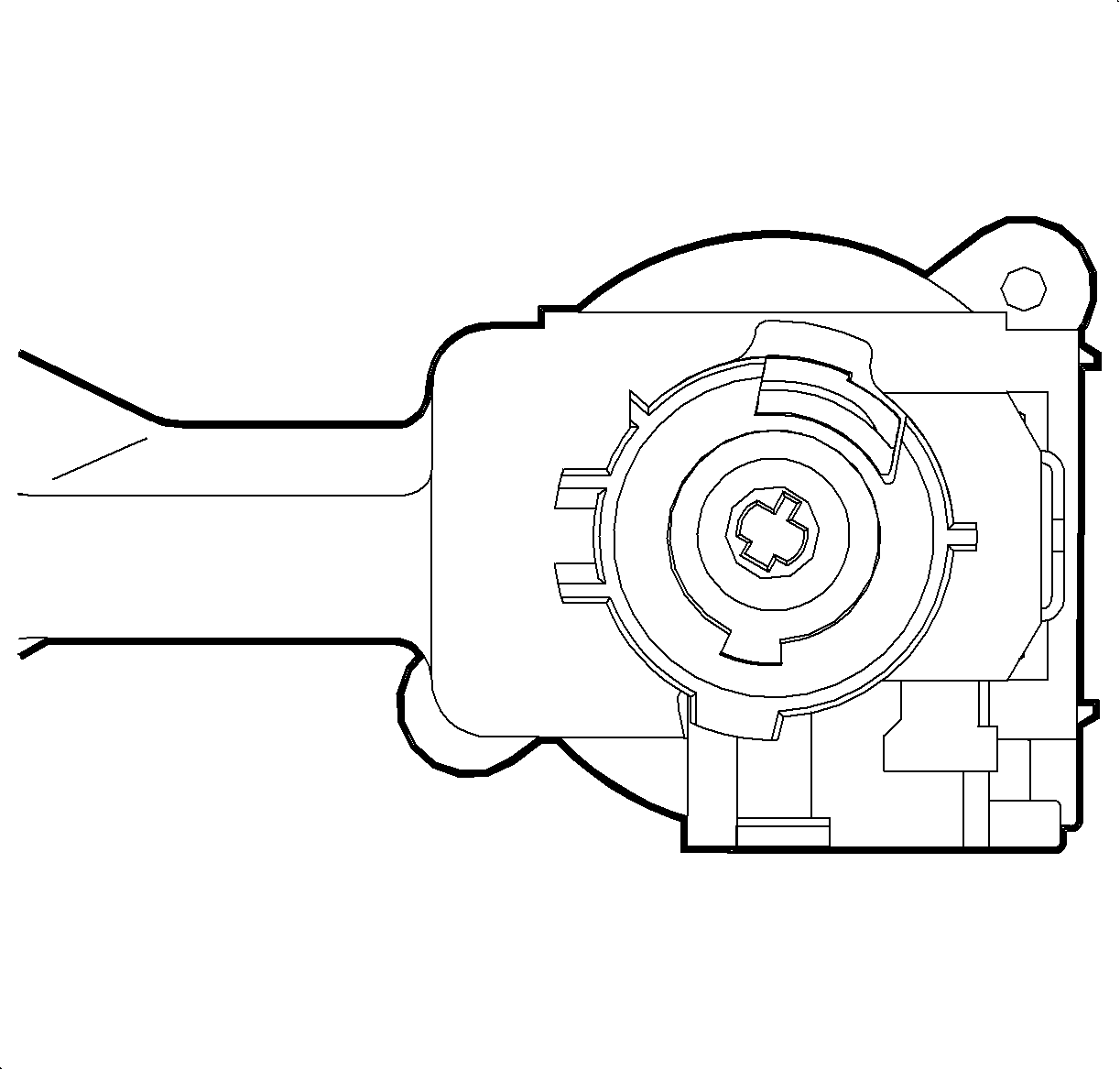
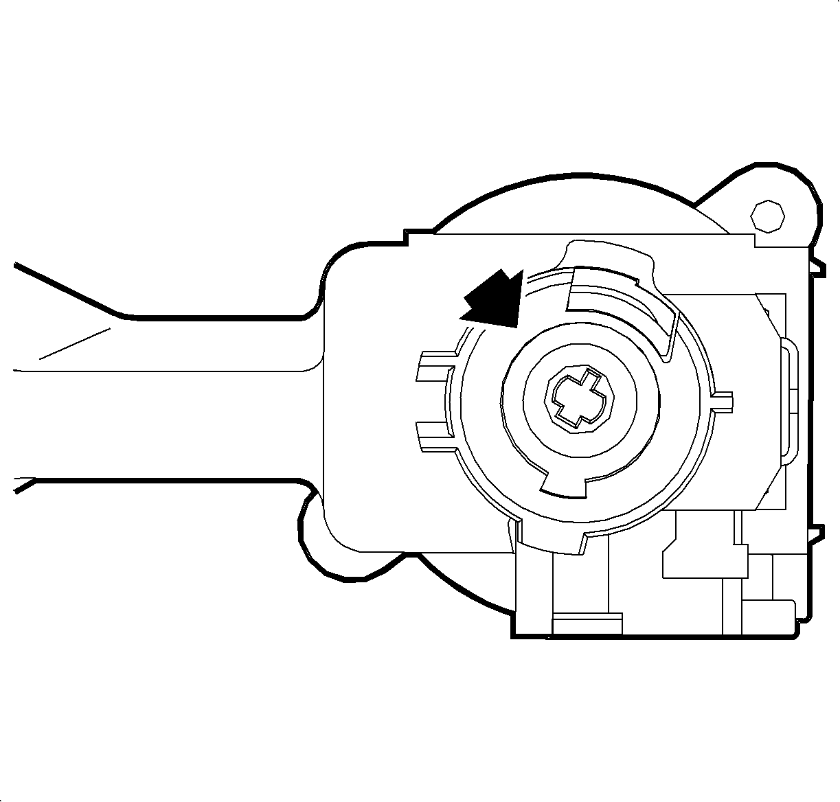
Important: The actuator blade within the ignition module must be in the ACC position to install the lock cylinder assembly. If rotated, replace it to the ACC position using needle nose pliers.

Tighten
Tighten the steering column shroud fasteners to 1.5 N·m (13 lb in).
Tighten
Tighten the battery terminal blot to 17 N·m (13 lb ft).
Parts Requirements:
Part Number | Description |
|---|---|
21019052 | Cylinder Kit-Ign LK (Uncoded) |
21019793 | Housing Kit-Ign and Start SW Auto/4Cyl (MN4) or Auto/6Cyl (MN5) |
21019794 | Housing Kit-Ign and Start SW Man/4Cyl (M79) or Man/4Cyl (MU3) |
22679709 | Tumbler-Ign LK #1 |
22679710 | Tumbler-Ign LK #2 |
22679711 | Tumbler-Ign LK #3 |
22679712 | Tumbler-Ign LK #4 |
12458193 | Spring-Ign LK Cyl Tumb |
Part Number | Description |
|---|---|
21171504 | Cylinder Kit-Ign LK (Uncoded) |
21060165 | Housing ASM-Ign and Start SW |
21060092 | Bolt/Screw-Ign LK Cyl Case |
22679709 | Tumbler-Ign LK #1 |
22679710 | Tumbler-Ign LK #2 |
22679711 | Tumbler-Ign LK #3 |
22679712 | Tumbler-Ign LK #4 |
12458193 | Spring-Ign LK Cyl Tumb |
To receive credit for this repair during the warranty coverage period, submit a claim through the Saturn Dealer System for E7200 (Cylinder, Ignition Lock - R and R or Replace) or E7650 (Module, Ignition lock Cylinder (Housing) - R and R or Replace), or if another procedure is performed, refer to the appropriate Electronic Labor Time Guide for the correct Labor Operation Code and Time.
Important: Use labor operations E7650 (Module, Ignition Lock Cylinder (Housing) - R and R or Replace) if ignition lock cylinder could not be rotated with key. E7650 includes time to R7R lock cylinder: therefore, if E7650 is claimed, do not claim E7200.
