Odor from A/C at Vehicle Start-Up

| Subject: | Odor from A/C at Vehicle Start-Up (Remove Debris from Evaporator Case, Apply Cooling Coil Coating, and Install Delayed Blower Motor Control Module.) |
| Models: | 2000 Saturn L-Series vehicles |
Condition
A musty odor from A/C system, most noticeable at vehicle start-up.
Cause
An unpleasant (musty) odor from A/C outlets at vehicle start-up can be the result of microbial growth on the evaporator core.
Correction
Remove any debris from evaporator case, clean evaporator with disinfectant and install delayed blower motor control module according to the following procedures.
Important: Before installing the delayed blower motor control module, the following information must be explained to the customer.
Customer Information
The delayed blower motor control module will not affect normal A/C or blower motor operation. However, the delayed blower motor control module will activate the blower motor on high speed for approximately five minutes, if the A/C clutch has been continuously activated for four minutes or more. The delayed blower motor control module will wait approximately fifty minutes after the ignition is turned OFF before activating the blower motor. It is during this blower run time that condensate, that causes microbial growth, is removed from the evaporator core. The blower motor will be turned On with NO driver input if the conditions as stated above are met. The air rush sound created by the blower motor is noticeable from outside of the vehicle.
The parasitic current draw of the delayed blower motor control module, combined with the blower motor load, will lower the state of the charge of the vehicle's battery, and may negatively impact battery life depending on the driving habits of the customer.
Service Procedure - Cleaning and Cooling Coil Coating Application
Before starting procedure, obtain the following equipment and supplies:
| • | A/C System Cooling Coil Coating (P/N 12346390) |
| • | Cleaning Gun, OTC Tool SA9216NE |
| Caution: When applying cooling coil coating (P/N 12346390), ordinary safety glasses are not sufficient. |
| • | Safety goggles |
| • | When applying cooling coil coating (P/N 12346390), National Institute of Occupational Safety and Health (NIOSH) approved acid gas/organic vapor respirator with chlorine dioxide cartridges (3M® P/N 5103-small, 5203-medium, 5303-large), which are to be used with a pre-filter (P/N 5010) and retainer (P/N 501), or equivalents. |
| • | If using Cooling Coil Coating (P/N 12346390), safety glasses |
| • | Rubber gloves |
| • | Pedestal fan |
Dry evaporator by:
| • | Adjusting temperature to full hot |
| • | Adjusting mode to heater only |
| • | Turning RECIRC On |
| • | Making sure A/C button is Off |
| • | Close all doors and windows |
| • | Start engine and allow to reach operating temperature |
| • | Once engine reaches operating temperature, allow blower motor to operate on HI blower for 5 minutes. |
| Caution: Make sure vehicle is properly supported and squarely positioned on hoist. To help avoid personal injury, provide additional support to opposite end of vehicle that components are removed from. |
- Raise vehicle on a hoist.
- Check the HVAC module drain for blockage. If necessary, clear drain hole with a soft blunt tool such as the eraser end of a pencil.
- Lower vehicle from hoist.
- Place a drain pan directly below the HVAC drain to collect disinfectant or cooling coil coating and rinse water runoff.
- Open all doors and windows in the vehicle.
- Position pedestal fan so that it provides cross ventilation through the vehicle during the cleaning/coating procedure.
- Cover interior of vehicle with suitable protective coverings to protect surfaces from overspray.
- Allow the vehicle to cool down before performing cooling coil coating procedure.
- Remove the right side console extension.
- Remove the right side I/P lower dash insulator retainers.
- Pull the insulator rearward to detach from the forward insulator support.
- Remove the insulator support from the front of the dash studs by pulling rearward.
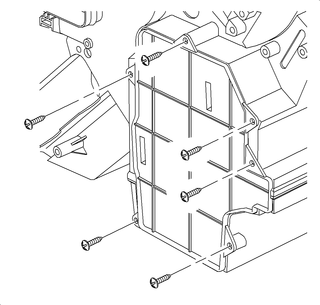
- Remove the right side heater duct assembly retainer and remove duct.
- Locate evaporator access door location on the right side of the module. The entire area inside the raised lip needs to be cut out.
- Using a sharp utility knife, cut through module wall, following inside of raised bead as a guide. Several passes may be necessary to do this.
- Carefully clean out any moisture or debris that may be inside the module.
- Put on rubber gloves, safety glasses, and NIOSH approved acid gas/organic vapor respirator.
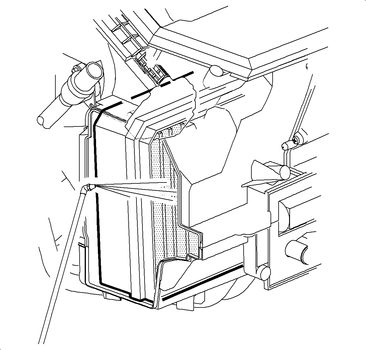
- Using the cleaning gun, OTC Tool SA9216NE (or equivalent siphon-type parts cleaning spray gun capable of delivering 2 ounces per minute of liquid with shop air at 552-620 kPa [80-90 psi]), insert siphon hose into container of cooling coil coating. Take care to place the bottle in a secure upright position to avoid spilling contents.
- Regulate the shop air to 276-414 kPa (40-60 psi).
- Insert nozzle tip of spray gun so spray pattern will be parallel to the evaporator face.
- Apply cooling coil coating using short bursts and rotating the nozzle tip up and down. This will allow for an even distribution and to ensure full coverage of the evaporator.
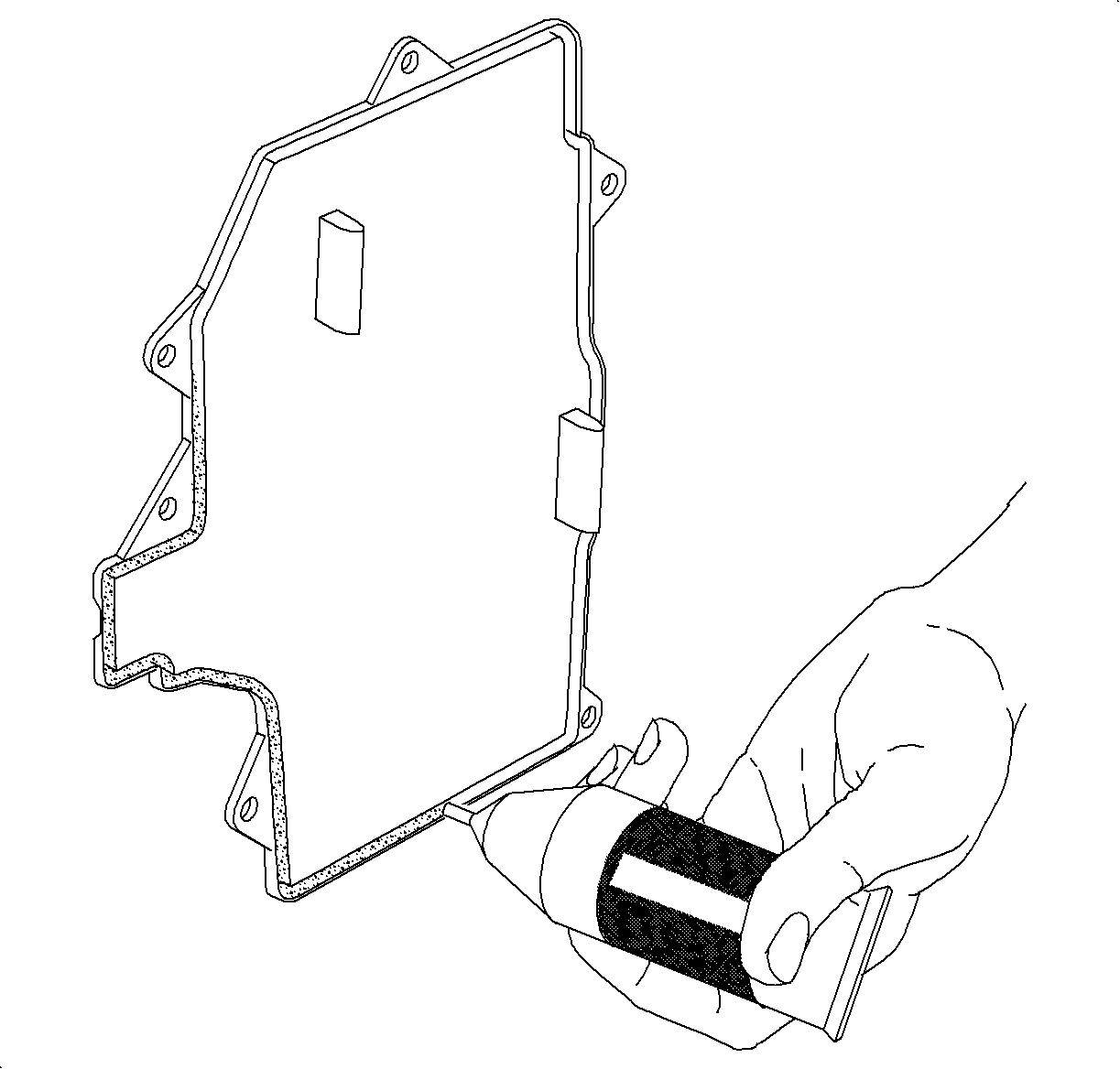
- Apply provided sealant in kit to service door at tongue and groove location as shown.
- Install evaporator core service door (P/N 22679783) to module and install screws.
- Install the right side heater duct assembly and the retainer.
- Install the insulator support to front-of-dash studs by sliding forward.
- Install the right side I/P lower dash insulator and retainers.
- Install the right side console extension.
- Allow evaporator core to soak for 15 minutes.
- Dry evaporator by:
- Properly dispose of cooling coil coating runoff collected in drain pan into a approved container.
- Remove the protective covering from interior of vehicle.
- Remove the pedestal fan from the area.
Caution: The following procedure should only be performed on a cold vehicle. It has been demonstrated that irritating vapors will be formed in the engine compartment if the cooling coil coating coming out of the drain outlet contacts hot engine components. Cooling coil coating can cause substantial, but temporary eye injury. Do not get cooling coil coating in eyes or on clothing. Wash thoroughly with soap and water after handling.
Caution: First Aid: If cooling coil coating gets into eyes, hold eyelids open and flush with a steady, gentle stream of water for 15 minutes. Obtain medical attention if irritation persists.
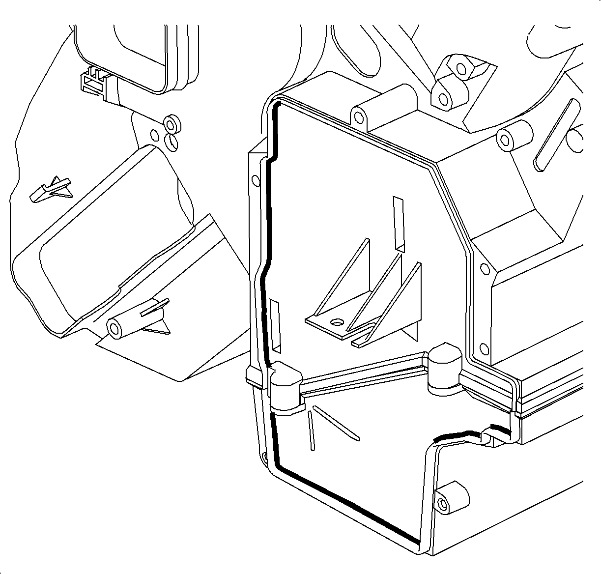
Caution: To avoid cutting internal components, cut only inside the raised bead area.
Notice: Do not cut through or damage raised bead, this bead will be used as a sealing surface when completing procedure.
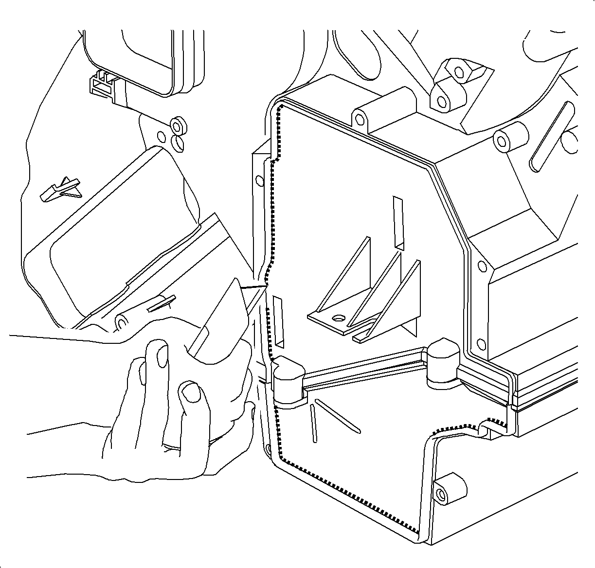
Notice: Use care when cleaning and removing debris around the evaporator as not to damage the fins.
Notice: Proper sealing is important to prevent condensation from leaking into the passenger compartment.
Tightening
Tighten Evaporator Core Service Door-to-HVAC Module Fasteners to 1 N·m
(9 lb in).
Important: The 5 minute drying time is an important step in curing the cooling coil coating to the evaporator.
| • | Adjusting the temperature to full hot |
| • | Adjusting the mode to heater only |
| • | Turning the RECIRC On |
| • | Making sure the A/C Button is Off |
| • | Open the windows 1/2 inch and close the doors |
| • | Start engine and allow to reach operating temperature |
| • | Allow blower motor to operate on HI blower for 5 minutes once engine reaches operating temperature |
Delayed Blower Motor Control Module Installation
Important: Before proceeding with the installation of the delayed blower motor control module, make sure the customer is fully aware of its function and operation.
The following parts are required to install the delayed blower motor control module:
Part Description | P/N |
Delayed Blower Motor Control Module Kit | 22679784 |
Splice Sleeve - Salmon 2 Required | 12089189 |
Splice Sleeve - Blue 1 Required | 12089190 |
Splice Sleeve - Yellow 2 Required | 12089191 |
Terminal End - 0.5 to 0.8 gage 1 Required | 12034046 |
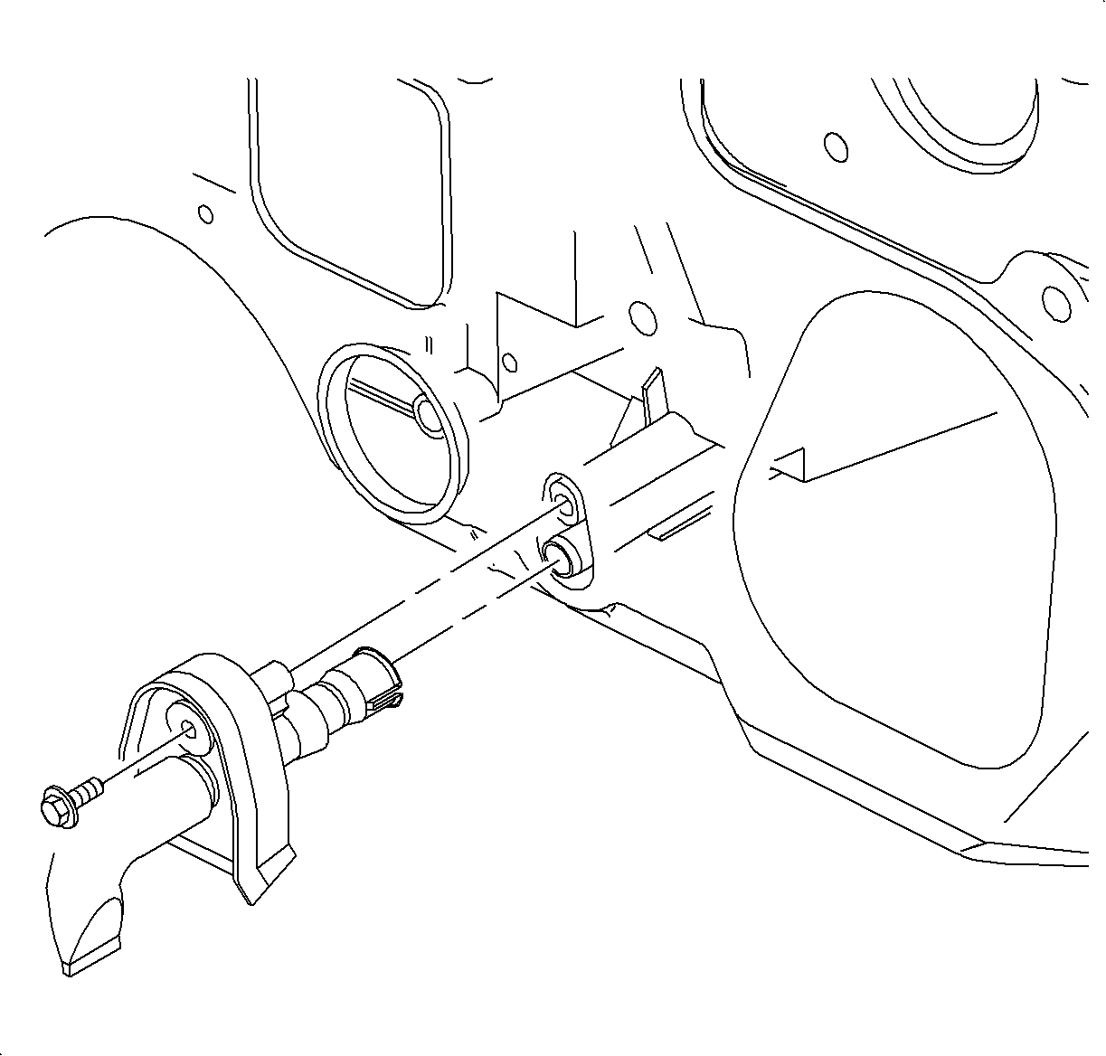
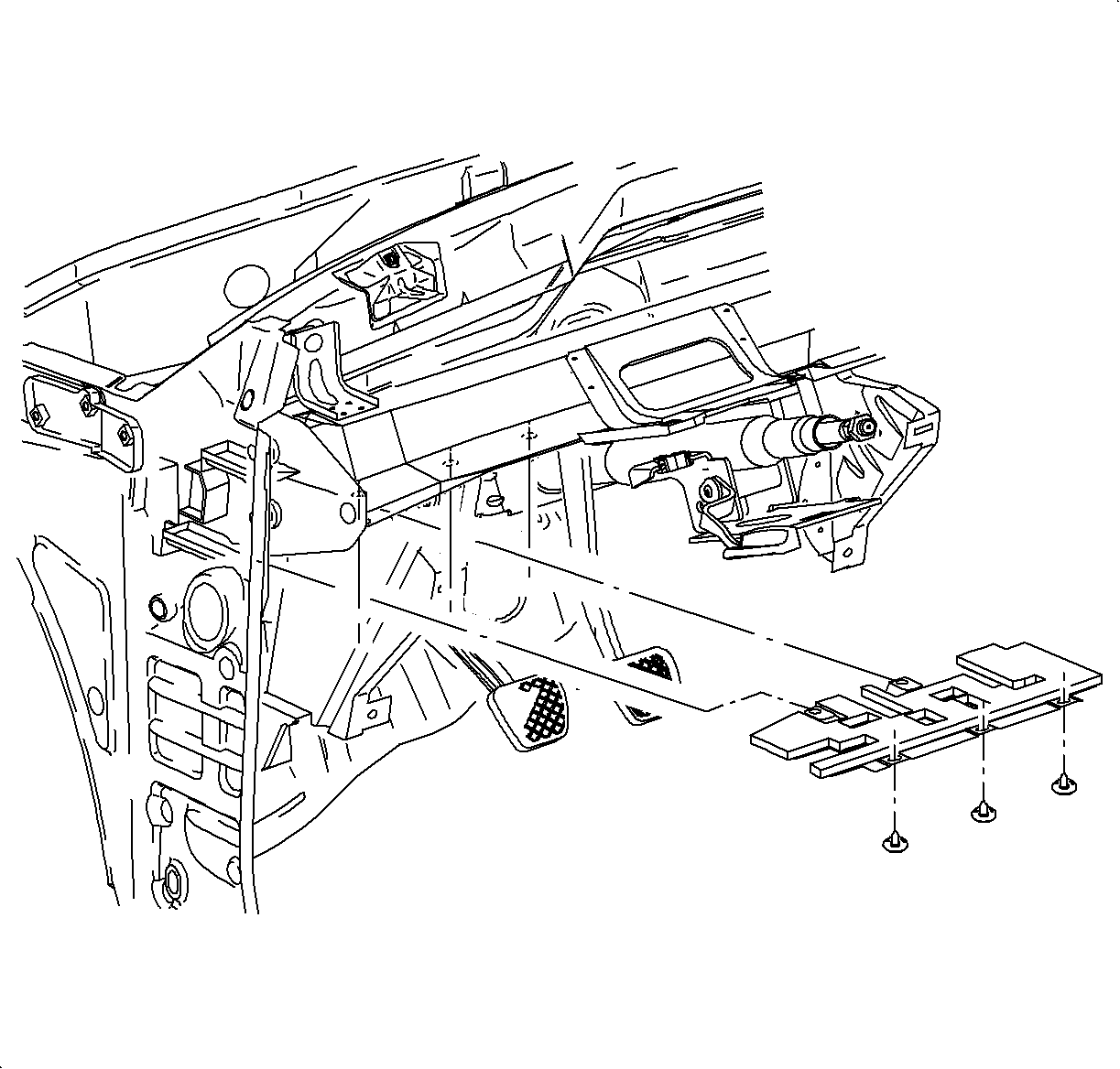
- Disable the SIR system. (Refer to "SIR Disable/Enable" procedure in the 2000/2001 Restraints Service Manual).
- Record radio preset stations and disconnect the negative battery cable.
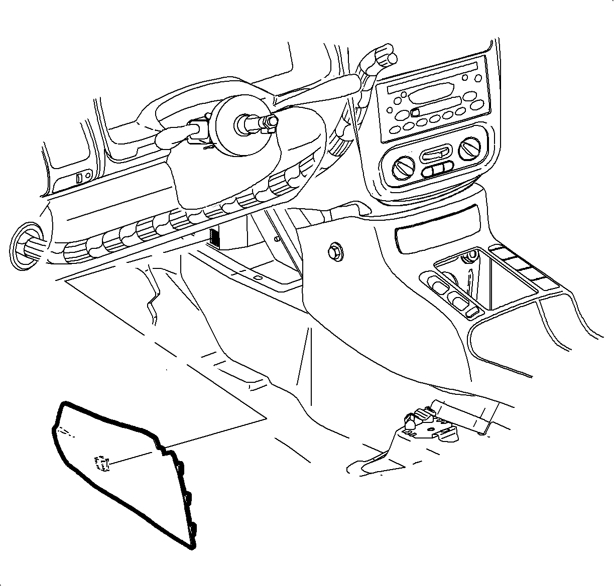
- Remove left side I/P lower dash insulator retainers.
- Pull insulator rearward to detach from forward insulator retainers.
- Remove left side console extension.
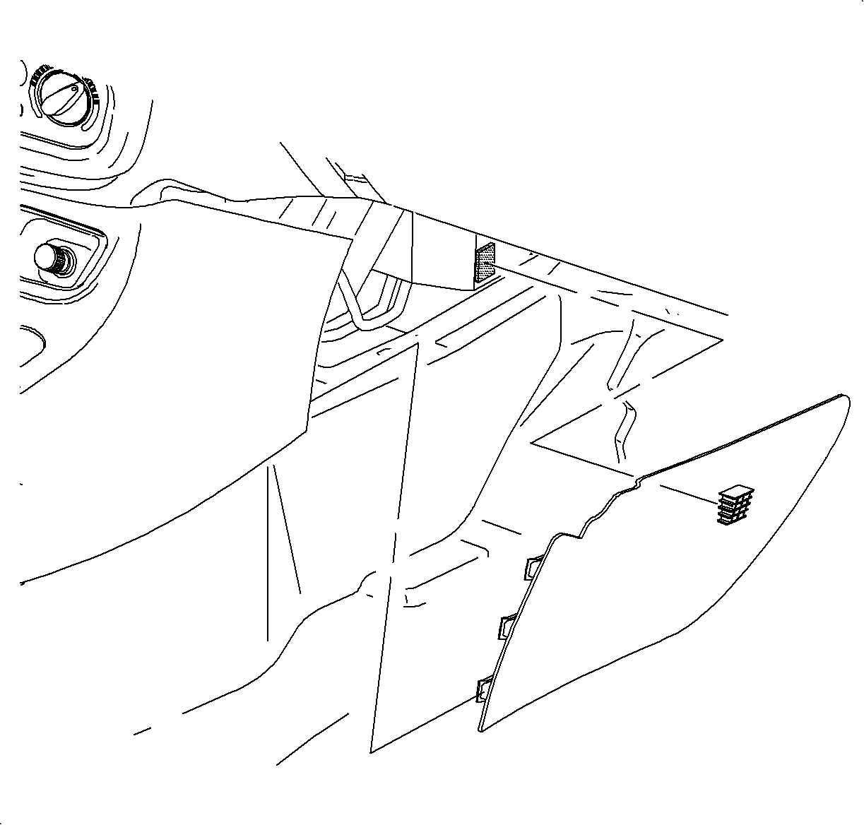
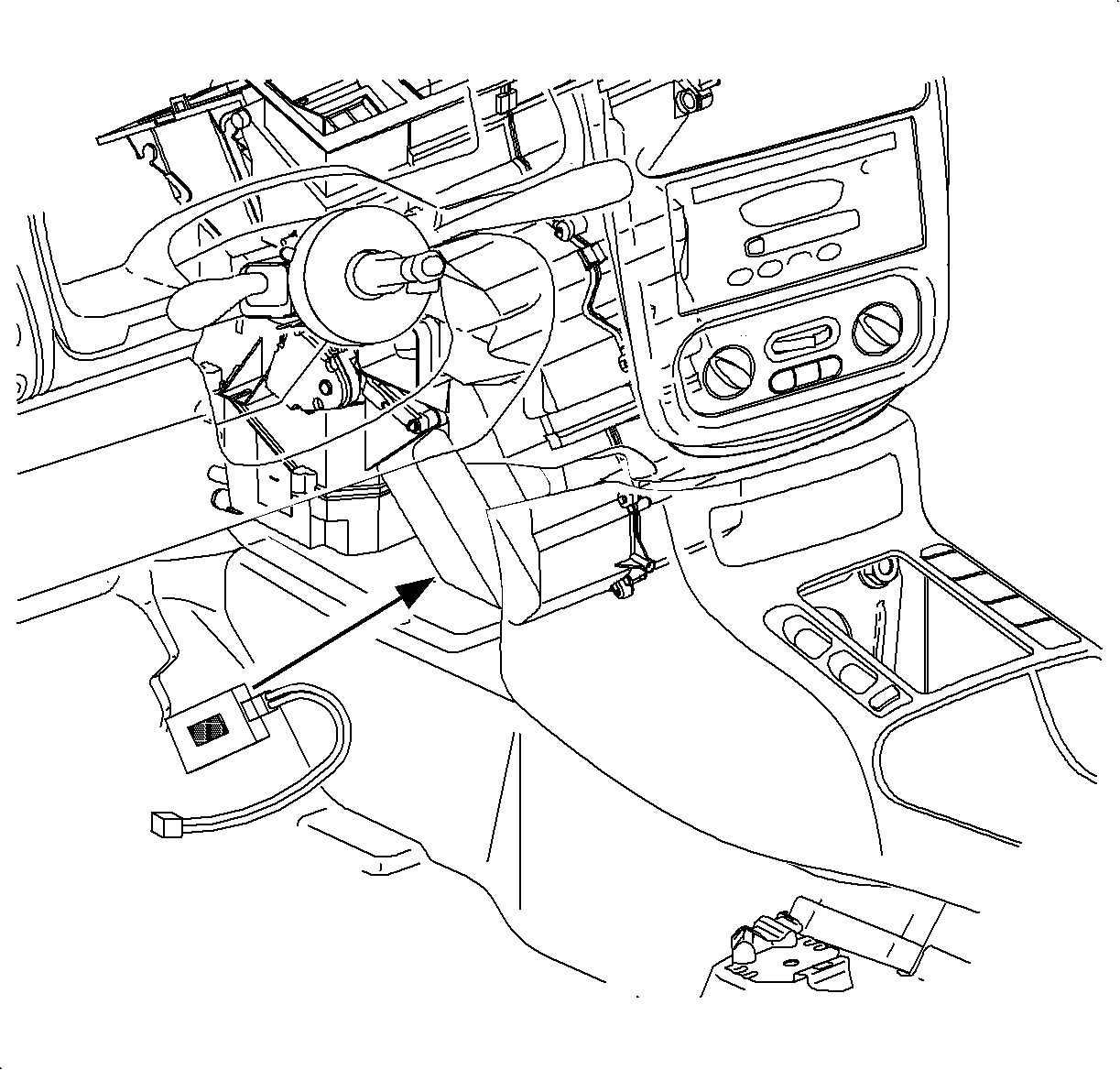
- From the driver's side of the vehicle, wipe clean the bottom horizontal surface of the HVAC module.
- Peel the backing off of the hook and loop retainer and install delayed blower control module with the wiring harness facing towards the passenger side and ensure back edge of the delayed blower control module is flush with the side of the HVAC module. Press firmly to seat.
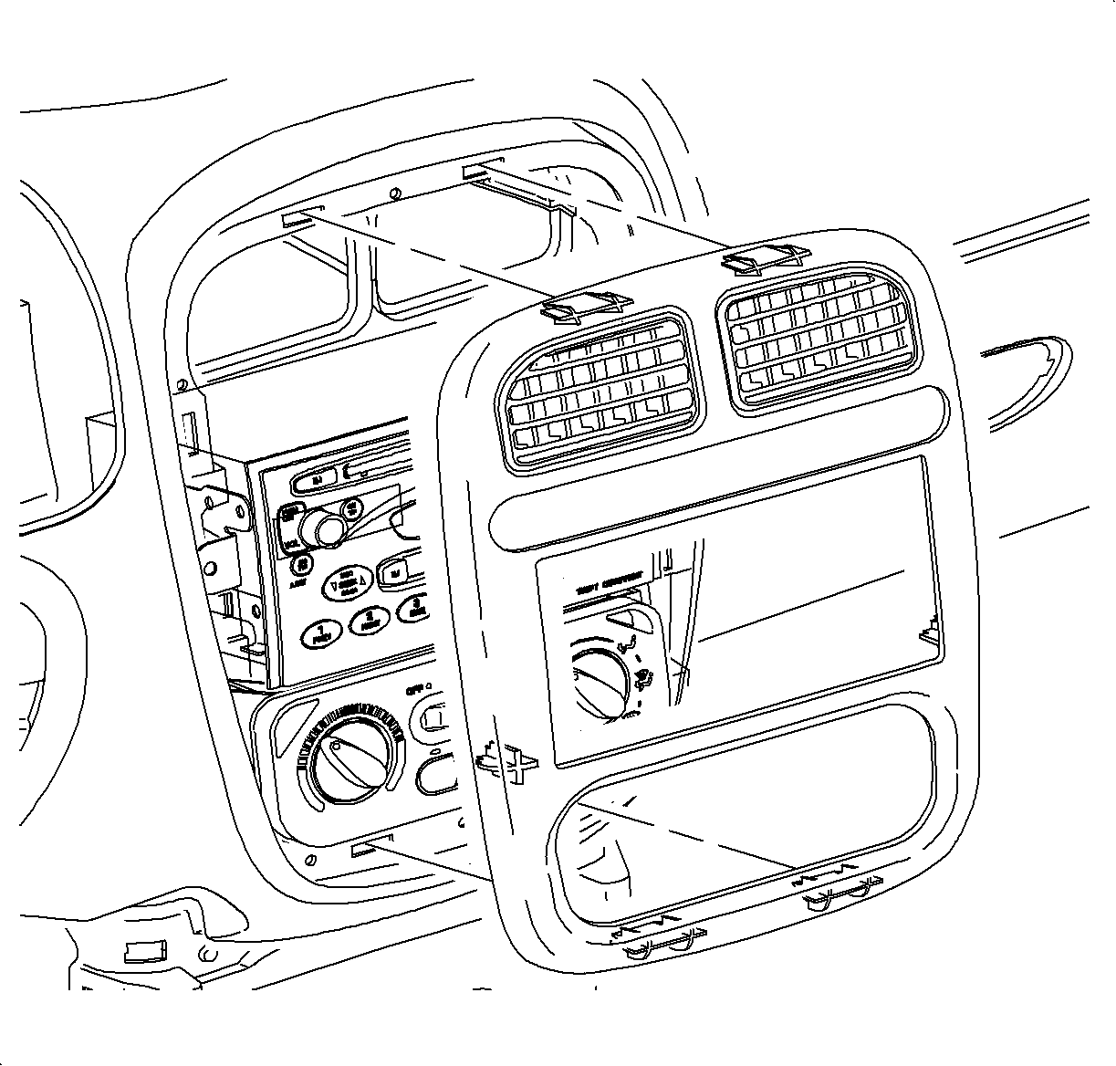
- Remove the radio bezel.
- Remove the radio and disconnect the electrical connectors.
- From Center I/P opening:
- Make the following splices at the HVAC inline BLK 12-way connector.
- Make the following splices at the Radio gray 24-way connector:
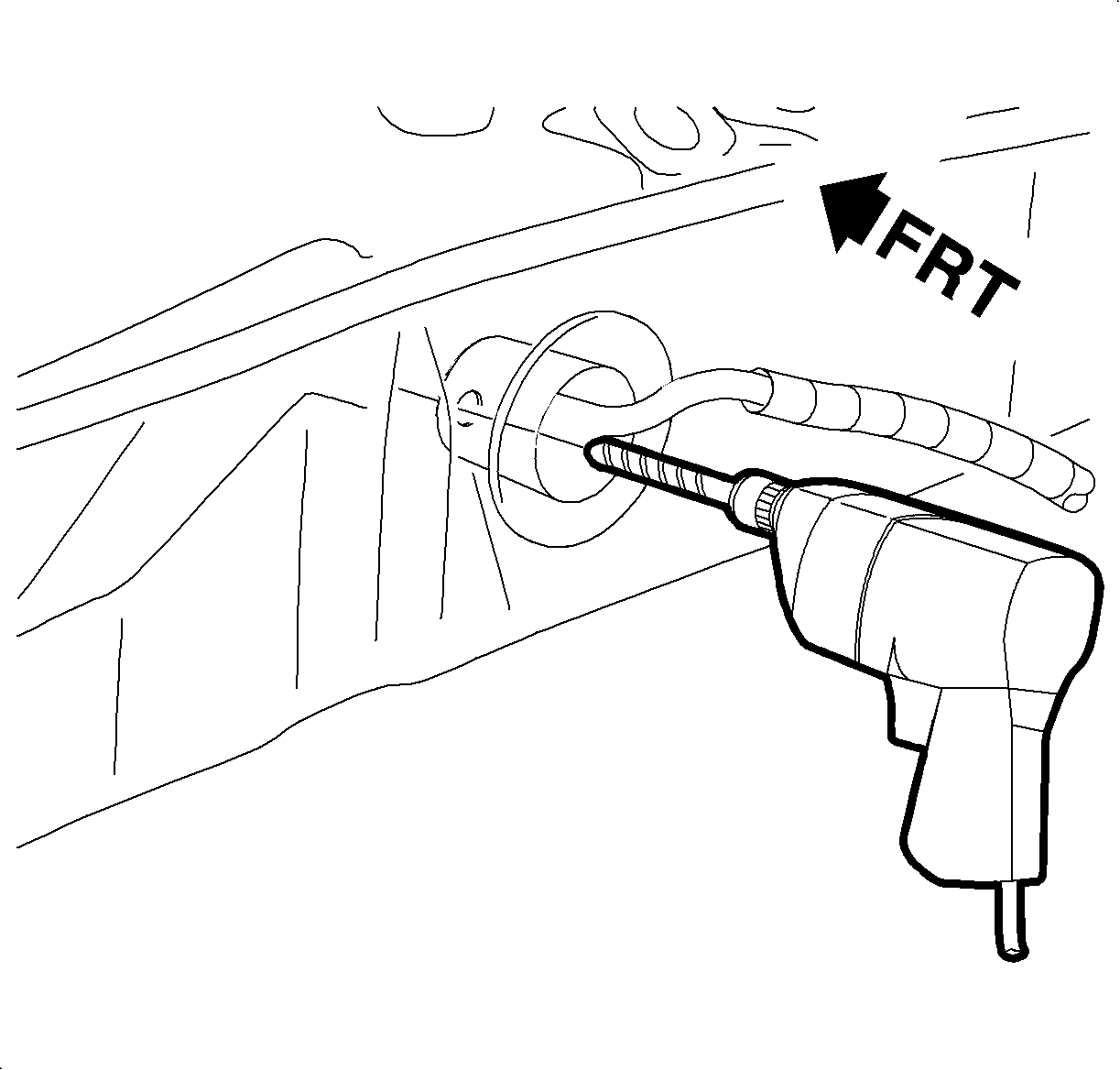
- From inside the vehicle, carefully drill a hole through left side (ten o'clock position) of the engine harness grommet, using a 2.0 mm drill bit.
- Locate the WHT wire (pin E), from delayed blower module and tape the wire onto the end of an awl and push through drilled hole in grommet. From the engine compartment untape WHT wire from awl and pull wire all the way through.
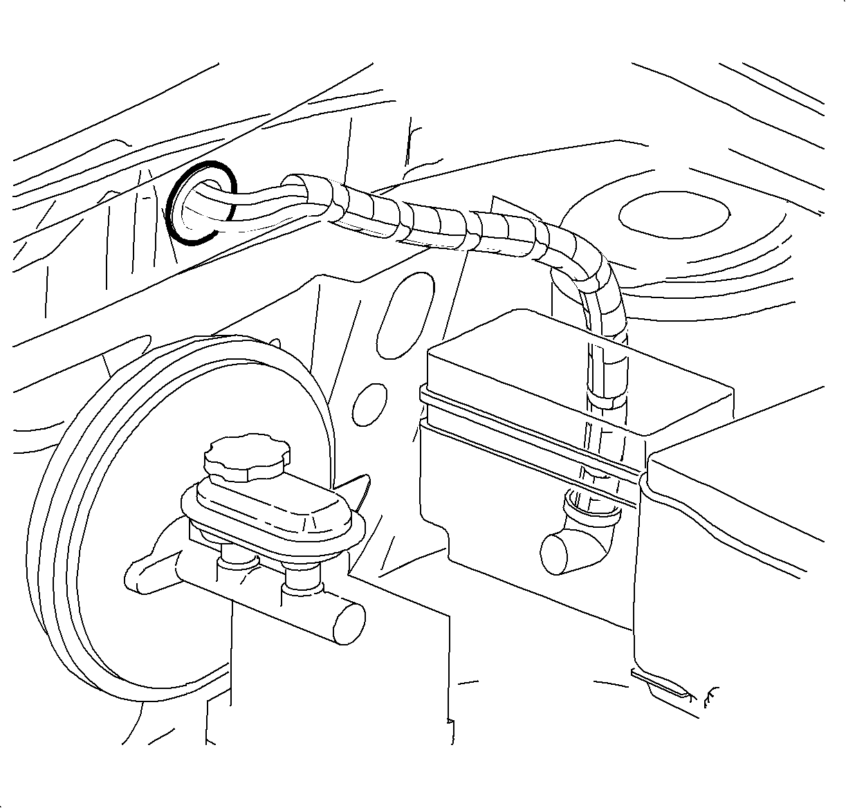
- Remove the battery shield.
- Unsnap the engine coolant reservoir line from the fuse block cover.
- Open the UHFB and disconnect the UHFB black 68-way connector (L61) or gray 68-way connector (L81) and then:
- Open the engine harness conduit from UHFB to the bulkhead.
- Route WHT wire from the delayed blower motor along this harness, placing the wire inside the conduit.
- Using electrical tape spot tape the engine harness.
- Close the UHFB.
- Install the coolant reservoir line.
- Install the battery shield.
- Inside the vehicle, solid tape the WHT wire from the delayed blower motor to the I/P harness every 2-3 inches.
- The BLU wire from the delayed blower motor is unused. Tape end of BLU wire and tape back to the jumper harness of the delayed blower control module.
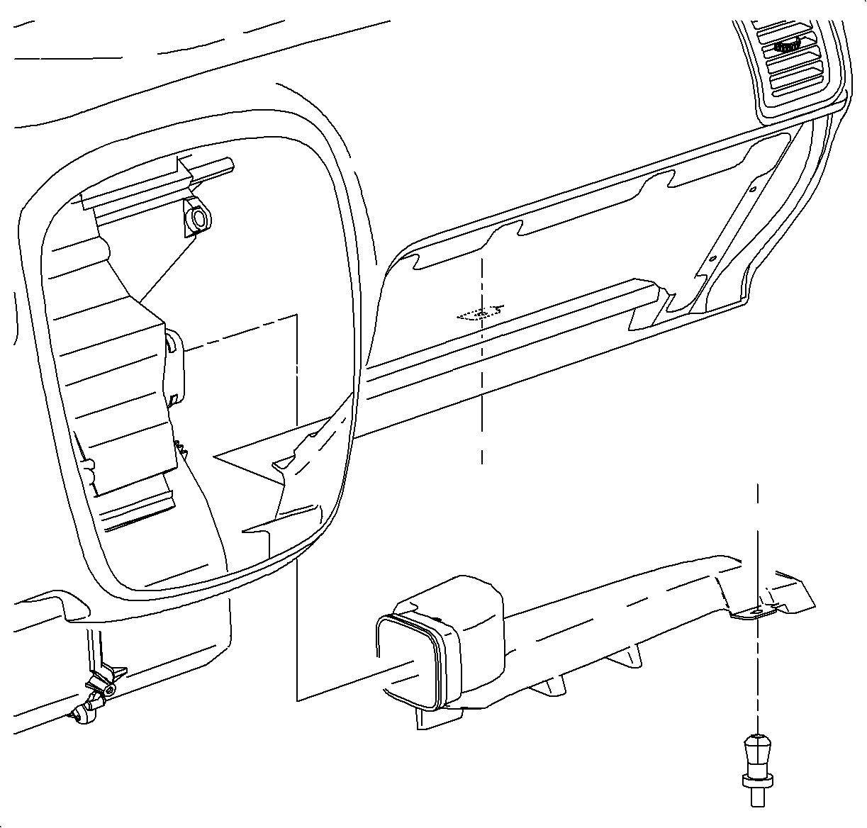
- Attach the top half of "Notice" label provided in the kit to blower motor cover. This can be accessed by removing the passenger compartment air filter in the engine compartment. Attach the bottom half of the "Notice" label to the inside of the left console extension assembly.
- Connect the negative battery cable.
- Proceed to "Testing the Delayed Blower Motor Control Module" and verify operation. After operations is verified, proceed to next step.
- Disconnect the negative battery cable.
- Connect the electrical connections and install the radio.
- Install the radio bezel.
- Install the left console extension assembly.
- Enable the SIR system. Refer to SIR Disable/Enable procedure in the 2000/2001Service Manual.
- Connect the negative battery cable.
- Set the radio station presets.
- Clear any SIR diagnostic trouble codes that may have set during delayed blower motor control module testing. Refer to the 2000/2001 Service Manual.
Caution: When performing service on or around SIR components or SIR wiring, follow the Cautions and Procedures in the SIR service manual to temporarily disable the SIR system. Failure to follow the disable procedures could result in possible airbag deployment, personal injury or otherwise unneeded SIR system repairs.

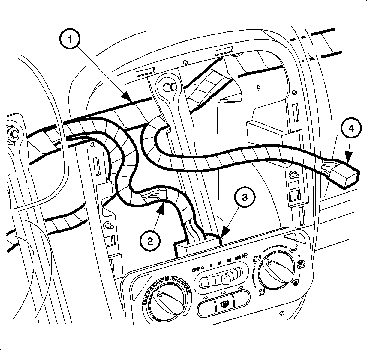
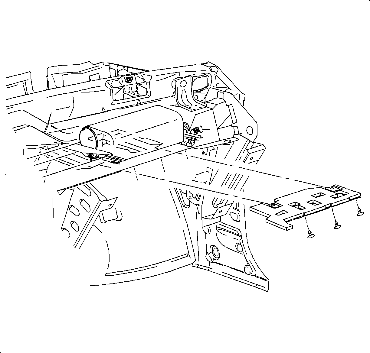
| 10.1. | Route the delayed blower motor control module harness down to delayed blower control module by placing the harness between the left side H Brace and HVAC module. Make sure the harness is routed between the main I/P body harness and the HVAC module. |
| 10.2. | Connect jumper harness to delayed blower motor control module pigtail. |
| • | (1) Main I/P body harness |
| • | (2) HVAC inline connector |
| • | (3) HVAC control head connector |
| • | (4) Radio connector |
| 10.3. | -- |
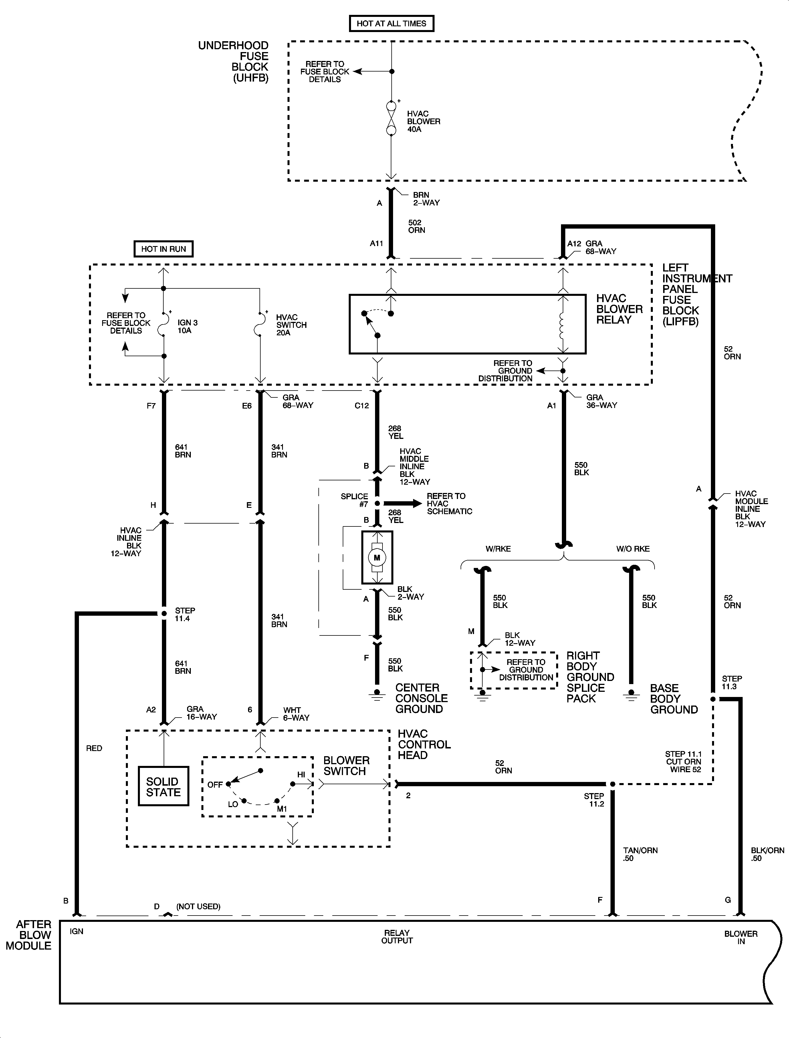
| Important: For steps 11 through 15, refer to the electrical schematic on pages 12 and 13. |
| Important: For information on splicing wires, refer to "Wiring Splicing" instructions in this bulletin. |
| 11.1. | At Pin A, cut orange wire (circuit 52), 76 mm (3 in) from connector on the side going to the HVAC control head, then: |
| 11.2. | Using a yellow splice sleeve, splice the other half of the ORN 5.0 mm (10 gage) wire from HVAC inline connector that goes to the I/P body harness into BLK/ORN 0.5 mm (20 gage) wire (pin F) from delayed blower control module. |
| 11.3. | Using a yellow splice sleeve, splice the other half of the ORN 5.0 mm (10 gage) wire from HVAC inline connector that goes to the I/P body harness into BLK/ORN 0.5 mm (20 gage) wire (pin G) from delayed blower control module. |
| 11.4. | At terminal H, using a salmon (pink) splice sleeve, splice BRN 0.35 mm (22 gage) wire from HVAC inline connector into RED 0.50 mm (20 gage) wire from delayed blower control module. |
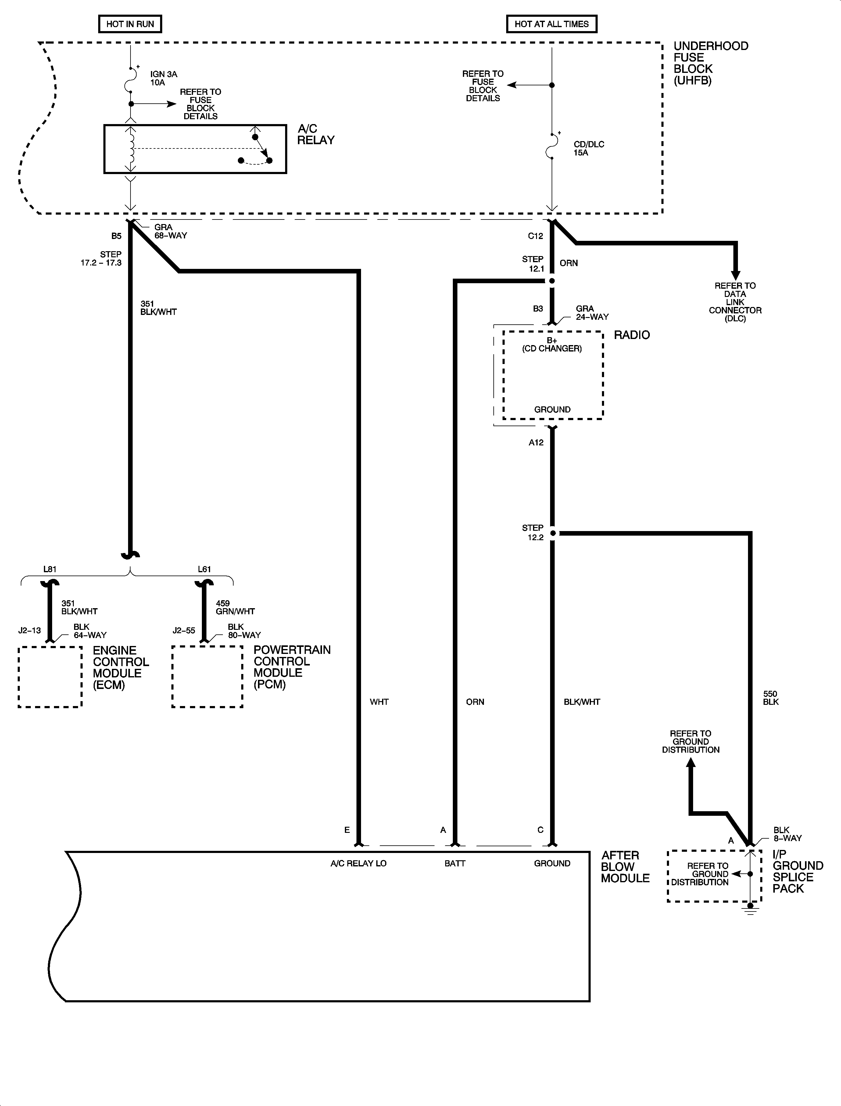
| 12.1. | At terminal B3, using a salmon (pink) splice sleeve, splice ORN 0.50 mm (20 gage) wire from Radio 24-way connector into ORN 0.50 mm (20 gage) (pin A) wire from delayed blower control module. |
| 12.2. | At terminal A12, using a blue splice sleeve, splice BLK 1.0 mm (16 gage) wire from Radio 24-way connector into BLK/WHT 0.50 mm (20 gage) (pin C) wire from delayed blower control module. |

| 17.1. | Locate and remove terminal C4 (L61) GRN/WHT wire or A7 (L81) BLK/WHT wire from the black (L61) or gray (L81) UHFB 68-way connector. |
| 17.2. | Cut off the terminal end from the GRN/WHT wire or BLK/WHT wire. |
| 17.3. | Splice GRN/WHT (L61) or BLK/WHT (L81) wire from UHFB 68-way connector and WHT wire from delayed blower control module onto terminal end P/N 12034046 0.5-0.8 mm (20-18 gage). |
| 17.4. | Connect the 68-way connector to the UHFB. |
Tighten
Tighten the battery terminal bolts to 17 N·m (13 lb ft).
Important: Do not install parts that have been removed until correct operation of the delayed blower module has been verified.
Tighten
Tighten the battery terminal bolts to 17 N·m (13 lb ft).
Wire Splicing
With the wiring used in the Saturn vehicles, it is recommended that approved Packard Electric Crimp and Seal Splice Sleeves (or equivalent) be used.
- Remove the insulation from both ends, recommended strip length is 9.5 mm (3/8 in). Caution must be used to prevent cutting the wire strands. Locate new splice a minimum of 40 mm (1 1/2 in) from an outlet or other splice.
- Determine proper sleeve fro gage of wire. Position stripped ends in sleeve until wires hit stop.
- Hand crimp sleeve using the approved crimping tool. Gently tug on wires to make sure they are secure before applying heat for shrinking to them.
- Check for continuity in the wire.
- Apply heat using Ultratorch® (or equivalent), heating splice sleeve to 175°C (347°F). Heat until glue flows around edges of splice sleeve.
Important: When using the salmon splice sleeve with 0.35 mm (22 gage) wire, remove 19 mm (3/4 in) of insulation. Bend the stripped portion in half to double the thickness of the wire going into the splice sleeve. Twist the tripped, doubled wire and insert into the splice sleeve.
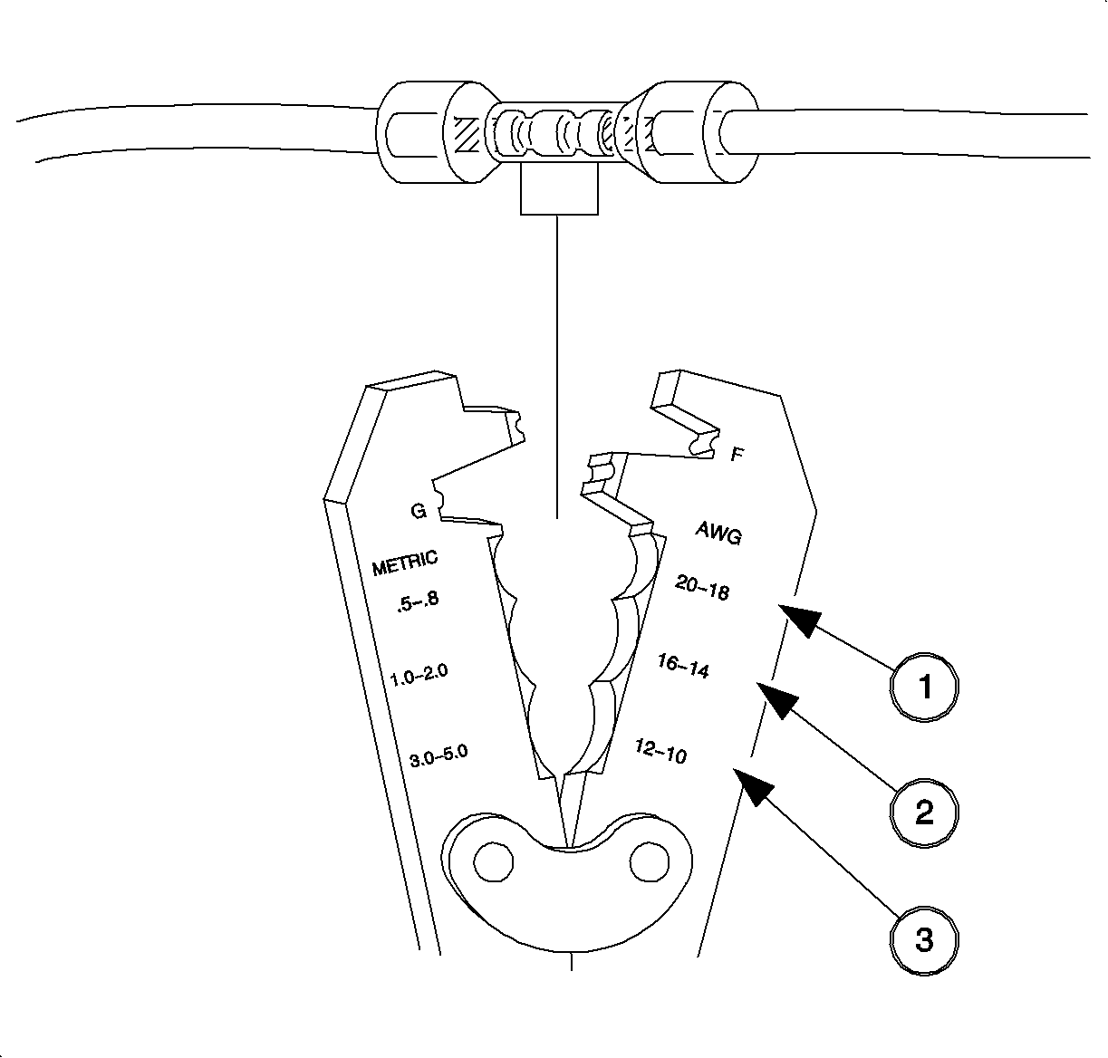
Important: When splicing three wire ends into one splice sleeve, insert both wires into one end; one cut wire end from vehicle harness and new splice wire end into one side of the splice sleeve until wires hit stop. Hand crip using approved crimping tool. Insert remaining cut wire end from vehicle harness into other side of splice sleeve and crimp.
Caution: Do not use a match or open flame to apply heat to splice sleeve.
| Salmon | Blue | Yellow |
|---|---|---|---|
Wire Size | 0.35, 0.50, 0.80 | 1.0, 2.0 | 3.0, 5.0 |
Gage | 22, 20, 18 | 16, 14 | 12, 10 |
Packard P/N* | 12089189 | 12089190 | 12089191 |
Special Tools P/N** | 217670 | 217671 | 217672 |
* Order through Packard at 1-800-PACKARD (1-800-722-5273) ** Order through Saturn Special Tool Catalog. Included with Terminal Repair Kit (SA9138Z) | |||
Testing The Delayed Blower Motor Control Module
A full functional check of the delayed blower motor control module is required to assure that all electrical connections are connected properly and it is functioning as designed.
- Locate the GRN wire at cavity H of the delayed blower motor control module and insert a metri-pack 280 series male test adapter into cavity H until contact is made with GRN wire terminal in the delayed blower motor control module pigtail connector.
- Start the engine and turn On A/C and verify that compressor clutch engages. With clutch engaged, apply battery voltage to the test adapter installed in step 1 above.
- Disconnect the voltage to the test adapter and remove adapter from the connector.
- If the delayed blower motor control module runs for one second, go back to installation procedures and install parts removed from vehicle. If the delayed blower motor control module does not run for one second, go back to installation procedures and check all wiring connections. Refer to Delayed Blower Motor Control Module Diagnosis in this bulletin if functional check is not passed.
Important: Do not disconnect the jumper harness connector from the delayed blower motor control module pigtail connector or system test will not function.
After 30 seconds, turn the ignition Off with voltage still applied to the test adapter. Approximately 10 seconds after the ignition is turned Off, the blower motor will run for one second if the delayed blower motor control module is wired correctly.
Delayed Blower Motor Control Module Diagnosis
Cause | Solution | ||||
|---|---|---|---|---|---|
DEFINITION: Vehicle running, high blower setting does not operate | |||||
The blower in and blower out wires to the module are not properly connected. |
| ||||
Cause | Solution |
|---|---|
DEFINITION: Blower does not operate after specified delay time (Make sure that all wires to module are properly connected. Use a voltmeter to check that the proper signal is applied to each wire. | |
Test Mode Only -- GRN test wire from delayed blower motor control module is not properly connected to vehicle battery source. | Connect or jumper GRN test wire (pin H) to the vehicle's battery (not ignition). |
Proper signal not received from A/C compressor. | Make sure A/C compressor is connected electrically. Secondly, use a voltmeter to verify that A/C compressor low signal is zero volts when air conditioning is turned On. |
A/C compressor was not in operation long enough to trigger delayed blower motor control module. | Start engine and turn On A/C. Make sure A/C compressor clutch is continuously engaged for at least four minutes to trigger delayed blower motor control module. For test mode, run A/C for 30 seconds before turning Off engine. |
Parts Requirements
Part Number | Description | Qty |
|---|---|---|
12346390 | Coating -- A/C Evap Organic Matl Growth Prev. | 1 |
22679783 | Evaporator Service Door | 1 |
22679784 | Delayed Blower Control Module Kit | 1 |
12089189 | Splice Sleeve -- Salmon | 2 |
12089190 | Splice Sleeve -- Blue | 1 |
12089191 | Splice Sleeve -- Yellow | 2 |
12034046 | Terminal End -- 0.5 to 0.8 gage | 1 |
Claim Information
To receive credit for this repair during the warranty coverage period, submit a claim through the Saturn Dealer System as follows:
Case Type | Description | Labor Operation Code | Time |
|---|---|---|---|
VW | Install Delayed Blower Motor Control Module Package Note: Does not include time to Clean and Disinfect Evaporator Core; refer to D3319 | D3316 | 1.7 hrs |
VW | Core, Evaporator -- Clean and Disinfect | D3319 | 1.4 hrs |
Important: When it is necessary to clean and disinfect the HVAC system at the same time the delayed blower motor control module package is installed, submit labor operations D3319 as a "related line" to failed labor operation D3316.
