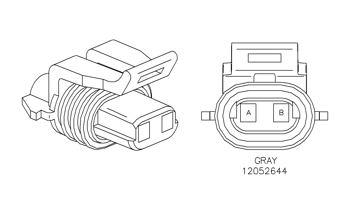
New Design Liftgate Lock Cylinder Case Connector Does Not Mate With Existing Liftgate Wiring Harness Connector

| Subject: | New Design Liftgate Lock Cylinder Case Connector Does Not Mate With Existing Liftgate Wiring Harness Connector (Replace Liftgate Wiring Harness Connector with New Design Connector Replacement Pack) |
| Models: | 2000 L-Series Wagons |
Condition
New design wagon liftgate lock cylinder case P/N 22689998, will not mate with the existing liftgate wiring harness connector.
Cause
This condition is caused by a introduction of a new design connector between the liftgate wiring harness and the micro-switch located in the liftgate lock cylinder case.
Correction
Replace liftgate wiring harness connector with new design connector replacement pack P/N 21022284.
Procedure
- Remove liftgate lock cylinder case. Refer to "Liftgate Lock Assembly" removal procedure in the Locks and Security of the 2000 Body/Electrical Volume II Service Manual.
- Locate and cut existing liftgate lock connector (BLK 2-way) from liftgate wiring harness.
- Cut replacement connector (GRA 2-way) wires to length.
- Splice wires into liftgate wiring harness.
- Install new liftgate lock cylinder case. Refer to "Liftgate Lock Assembly" Installation procedure in the Locks and Security of the 2000 Body/Electrical Volume II Service Manual.

| • | Cavity A - BLK wire, circuit 305 |
| • | Cavity B - ORN wire, circuit 340 |
Important: Saturn recommends that approved Packard Electric Crimp and Seal Splice Sleeves (or equivalent) be used.
| 4.1. | Remove insulation from both ends, recommended strip length is 9.5 mm (3/8 in.). Caution must be used to prevent cutting the wire strands. Locate new splice a minimum of 40 mm (1 1/2 in.) from an outlet or other splice. |
| Important: When using the salmon splice sleeve with 0.35 mm (22 gage) wire, remove 19 mm (3/4 in.) of insulation. Bend the stripped portion in half to double the thickness of the wire going into the splice sleeve. Twist the stripped, doubled wire and insert into the splice sleeve. |
| 4.2. | Determine proper sleeve for gage of wire. Position stripped ends in sleeve until wires hit stop. (See Wire Size Table Below) |
| Important: When splicing three wire ends into one splice sleeve, insert both wires into one end; one cut wire end from vehicle harness and new splice wire end into one side of the splice sleeve until wires hit stop. Hand crimp using approved crimping tool. Insert remaining cut wire end from vehicle harness into other side of splice sleeve and crimp. Hand crimp sleeve using the approved crimping tool. Gently tug on wires to make sure they are secure before applying heat for shrinking to them. |
| 4.3. | Check for continuity in the wire. |
| Caution: DO NOT USE A MATCH OR OPEN FLAME TO APPLY HEAT TO SPLICE SLEEVE. |
| 4.4. | Apply heat using Ultratorch®(or equivalent), heating splice sleeve to 175° C (347° F). Heat until glue flows around edges of splice sleeve. |
Wire Size Information
Wire Size (In millimeters)Wire Gage | .35 - .50 - .80 22 - 20 - 18 | 1.0 - 2.0 16 - 14 | 3.0 - 5.0 12 - 10 | |
Packard P/N * | Special Tools P/N ** |
|
|
|
12089189 | (217670) | - Salmon - |
|
|
12089190 | (217671) |
| - Blue - |
|
12089191 | (217672) |
|
| - Yellow - |
* Order through Packard at 1-800-PACKARD (1-800-722-5273)
** Order through Saturn Special Tool Catalog. Included with Terminal Repair Kit (J44020)
Parts Information
Part Number | Description |
|---|---|
22689998 | CYLINDER KIT-L/GATE LK |
21022284 | CONNECTOR-SW-L/GATE REL |
Warranty Information
To receive credit for this repair during the warranty coverage period, submit a claim through the Saturn Dealer System for B5810 (Cylinder, Tailgate Lock - R & R or Replace), or if another procedure is performed, refer to the appropriate Electronic Labor Time Guide for the correct Labor Operation Code and Time.
