2000 Saturn L-Series Vehicles (All Models)

| Subject: | REPLACE BOLT AND SEAL WASHER AT SUCTION PIPE AND DISCHARGE LINE (COMPRESSOR SIDE), EVACUATE/RECHARGE A/C SYSTEM REFRIGERANT, IF NECESSARY |
| Models: | 2000 SATURN L-SERIES VEHICLES (ALL MODELS) |
All Saturn Retailers and Authorized Service Providers
Saturn has decided that certain 2000 model year L-Series vehicles were produced with improperly tightened suction pipe and discharge line bolts at the air conditioning compressor. If either bolt is not adequately tightened, a refrigerant leak will occur, and the air conditioner will not blow cold air.
To prevent the possibility of this condition occurring, Retailers will conduct an air conditioner system performance test and tighten the suction pipe and discharge line bolts. If a leak is found, Retailers will replace the suction pipe and discharge line bolts and seal washers and evacuate and recharge the air conditioning system.
Vehicles Involved
Only selected 2000 model year L-Series Saturn vehicles within the following VIN range will require this campaign:
YY645945 - YY679868
You must verify campaign involvement through your AS400 system, or with the listing attached to this bulletin. It is important to note that campaign claims will only be paid on involved vehicles.
Owner Notification
Owners of all involved vehicles will be notified of this campaign by Saturn. (Refer to the owner letter included in this bulletin.)
Facility VIN Listing
A list of vehicles assigned to you (Facility VIN Listing), which our records indicate were sold by or shipped to you, (or are located in close proximity to your facility) is enclosed.
This listing contains:
| • | Owner's name with address and telephone number; |
| • | Complete vehicle identification number (VIN); and |
| • | VINs of vehicles which according to Saturn records are in retail stock. |
The Facility VIN Listing (with owner information) is furnished to involved Retailers with the Product Campaign Bulletin. Although these vehicles are assigned to your facility, it is important to note that owners may elect to have their vehicle serviced at the Saturn Retail Facility of their choice.
Those Retailers not involved initially in this campaign will receive a message at the top of a blank Facility VIN Listing that states: NO VEHICLES ASSIGNED AT THIS TIME FOR CAMPAIGN 00-C-10.
These listings may contain owner names and addresses obtained from State Motor Vehicle Registration Records. The use of such motor vehicle registration data for any other purpose is a violation of law in several states. Accordingly, you are urged to limit the use of this listing to the follow-up necessary to complete this campaign. Those records updated with California DMV registration information will have the following message printed adjacent to the appropriate VIN: "OWNER INFORMATION UPDATED BY CALIFORNIA DMV; PUBLICATION PROHIBITED."
Retailer Responsibility
All unsold vehicles in Retailers' possession and subject to this campaign must be held at the retail facility and repaired per the service procedure of this campaign bulletin before owners take possession of these vehicles.
Retailers are to service all vehicles subject to this campaign at no charge to owners, regardless of mileage, age of vehicle, or ownership, from this time forward.
Owners of vehicles recently sold from your vehicle inventory are to be contacted by the Retailer and arrangements made to make the required correction according to the procedure contained in this bulletin.
In summary, whenever a vehicle subject to this campaign enters your vehicle inventory, or is in your retail facility for service in the future, please take the steps necessary to be sure the campaign correction has been made before selling or releasing the vehicle.
Transfer of Campaign Responsibility
Saturn vehicles that have been sold by you, which may be closer in proximity to another Saturn Retailer, may still appear on your Facility VIN Listing. If either you or the vehicle owner determines that it is more desirable for a vehicle on your Facility VIN Listing to be serviced by another Saturn Retailer, or if the customer's address has recently changed, campaign responsibility may be transferred by completing the following:
| • | Submit a Campaign Vehicle Action Report to your Customer Assistance Manager (CAM) at the Saturn Customer Assistance Center; OR |
| • | Submit an update in owner information to the Saturn Owner of Record system, via SERVICELINE XL, for Saturn Customer Assistance Center review and approval. |
A copy of the Campaign Vehicle Action Report is included for your reference. Additional copies can be ordered from Saturn Publications (1-800-828-2112, prompt 3, Item # S0397050). All changes to campaign responsibility will be reflected in your next Unfixed VIN Report.
All other changes in vehicle status (e.g., scrapped, stolen, etc.) are to be made in accordance with section 4.4.3 of the Retailer Service Reference Guide, "Notifying Saturn of Vehicle Status Change."
Parts Information
Saturn Service Parts Operations (SSPO) has sent stocking policies to all retailers for the required parts. Please check to ensure your policy has been turned on for weekly replenishment of these parts. The stocking policies were sent to aid the Retailer in campaign preparation and ensure minimal customer inconvenience.
Should additional parts be required, please order as needed.
Required Parts:
Part Number | Description | Quantity Required Per Vehicle |
|---|---|---|
52474375 | Seal - A/C CMPR & CNDSR Hose, Suction Pipe Condenser Side | 1 |
52474373 | Seal - A/C CMPR & CNDSR Hose, Discharge Line Condenser Side | 1 |
11516336 | Bolt/Screw - A/C CMPR & CNDSR Hose | 2 |
Incidental Parts:
Part Number | Description | Quantity Required Per Vehicle |
|---|---|---|
12345922 | Refrigerant - A/C | |
90570544 | Gasket - Exh Manifold Pipe | 2 |
90570845 | Nu t - Exh Manifold Pipe | 3 |
1110461 | Stud - Exh Pipe | 3 |
11089675 | Bolt/Screw - Exh Pipe | 3 |
Disposition of Replaced Parts
Retailers will scrap all replaced parts in a manner that ensures that they cannot be reused, remanufactured, or otherwise entered into the stream of commerce in the future.
Suggestions for Ensuring Customer Satisfaction
As you know, Saturn's success hinges upon our ability to execute superior customer support throughout the ownership experience, especially when important corrective actions such as this are required.
It is imperative that every effort is made to accommodate the affected owners. Additionally, priority should be given to customer vehicles over retail inventory vehicles. If you have any questions, please coordinate with the Saturn Customer Assistance Center to help ensure customer satisfaction.
Diagnostic Procedure
Perform the Performance Test - Vehicle Service Stall. Compare the recorded values to the corresponding system performance charts on the following pages.
Performance Test - Vehicle Service Stall
- Open the hood and leave the hood open during the entire test.
- Install a manifold gage set to the high side and the low side service ports. Verify that the gage set is visible from the inside of the vehicle.
- Start the engine.
- Turn the A/C Off - A/C button indicator light Off.
- Depress the re-circulation button so that the indicator light is lit.
- Install a thermometer into the right center outlet.
- Set the mode knob to the I/P outlet position - full counter-clockwise.
- Set the temperature knob to the full cold position - full counter-clockwise.
- Set the blower to third speed - M2.
- Open both front doors and the windows to stabilize the interior air temperature with the outside ambient temperature.
- Connect the Tech 2 to the data link connector (DLC).
- Using the Tech 2, verify the engine is operating at thermostat control temperature: 87°C (188°F) or greater.
- Use the appropriate Tech 2 special function to set the engine cooling fan speed to medium.
- Record the A/C system pressures and outlet temperature every minute for 5 minutes.
- Release the throttle to return the engine to idle.
- Release the Tech 2 control of the engine cooling fans.
- Compare the recorded values to the system performance charts on the following pages.
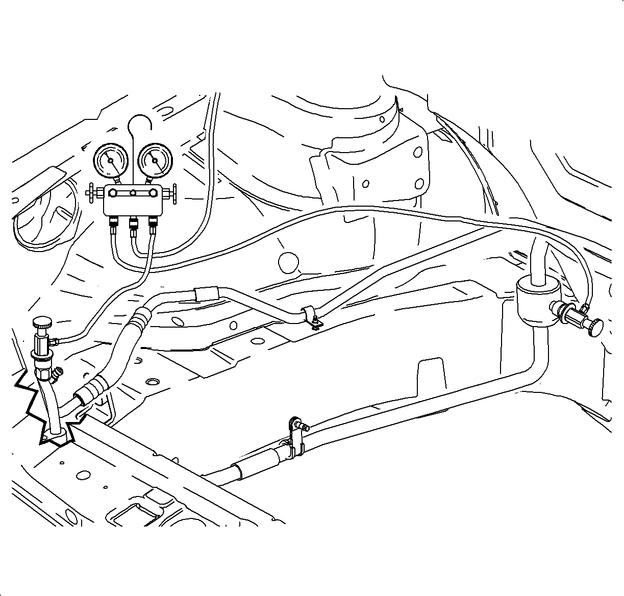
Important: If the ambient air temperature is lower than 0°C (32°F), the A/C compressor will not be enables.
Important: Perform this test in a service stall environment that protects the vehicle from wind that could cause incorrect pressure/temperature readings.
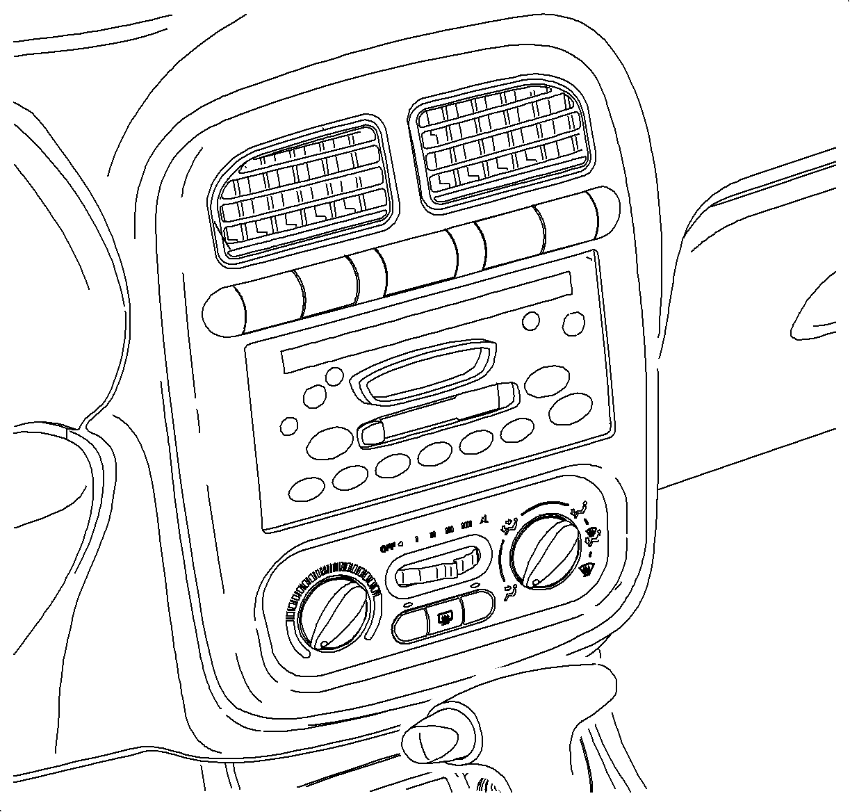
Important: A Tech 2 with version 19.005 or higher software is required to perform this test.
| • | For L81 engines: |
| 1. | Select Fan Control 1 and press ENTER. |
| 2. | Command the fan control On. The display will remain on HIGH for 10 seconds. After 10 seconds, the display will then indicate the fans are operating at MED. |
| 3. | Turn the A/C On - A/C button indicator light On. |
| Important: Allow the A/C system pressures to stabilize before beginning the test. |
| 4. | Using the throttle, increase the engine speed to 2000 RPM and hold. |
| • | For L61 engines: |
| 1. | Select the HVAC Performance special function and press ENTER. The display should indicate the fans are operating at MED. |
| 2. | Turn the A/C On - A/C button indicator light On. |
| Important: Allow the A/C system pressures to stabilize before continuing the test. |
| 3. | Using the Tech 2, increase the engine speed to 2000 RPM and hold. |
| • | If the recorded values match the "Normal System Performance" chart, tighten the bolts which secure the suction pipe and the discharge line to the compressor. Refer to the L61 or L81 Suction Pipe and Discharge Line Tightening Procedure in this bulletin. No other repairs are necessary. |
| • | If the recorded values match the "Low Refrigerant Charge" chart, proceed to the appropriate Service Procedure in this bulletin. |
| • | If the values do not match either "Normal System Performance" or "Low Refrigerant Charge" charts , match the values with the appropriate chart in the 2000/2001 L-Series HVAC Service Manual and make the necessary repairs. |
| • | When repairs are completed, make sure to tighten suction pipe and discharge line bolts to the specified tighten value. Refer to the appropriate Suction Pipe and Discharge Line Tightening Procedure in this bulletin. |
General System Condition - Low Refrigerant Charge - L61
If the ambient air temperature is ... | AND the low side pressure gage reads ... | AND the high side pressure gage reads ... | AND the right center air temperature is ... | ||||
|---|---|---|---|---|---|---|---|
°C | (°F) | kPa | (psi) | kPa | (psi) | °C | (°F) |
21-38 | (70-100) | Normal to High | Low | Slightly Cool to Warm | |||
KEY: POOR COOLING AT HIGHER AMBIENTS
THEN: The system is operating with a low charge.
| • | Leak test all components and connections. |
| • | If the refrigerant charge level is unknown, reclaim, evacuate and recharge the system with 0.95 kg (2.09 lb) of R134a refrigerant. |
| • | Run another performance test. |
General System Condition - Low Refrigerant Charge - L81
If the ambient air temperature is ... | AND the low side pressure gage reads ... | AND the high side pressure gage reads ... | AND the right center air temperature is ... | ||||
DEGREES °C | (°F) | SUCTION kPa | (psi) | DISCHARGE kPa | (psi) | OUTLET °C | (°F) |
21-38 | (70-100) | Normal to High | Low | Slightly Cool to Warm | |||
For the conditions described above, key POOR COOLING AT HIGHER AMBIENTS .
The system is operating with a low charge.
| • | Leak test all components and connections. |
| • | If the refrigerant charge level is unknown, reclaim, evacuate and recharge the system with 0.95 kg (2.09 lb) of R134a refrigerant. |
| • | Run another performance test. |
Normal System Performance Service Stall - L61
If the ambient air temperature is ... | AND the low side pressure gage reads ... | AND the high side pressure gage reads ... | AND the right center air temperature is ... | ||||
DEGREES °C | (°F) | SUCTION kPa | (psi) | DISCHARGE kPa | (psi) | OUTLET °C | (°F) |
21 | (70) | 200-213 | (29-31) | 723-916 | (105-133) | 5-8 | (41-46) |
27 | (80) | 193-207 | (28-30) | 999-1102 | (145-160) | 6-7 | (42-45) |
33 | (90) | 186-200 | (27-29) | 1275-1791 | (185-260) | 7-8 | (45-46) |
38 | (100) | 179-193 | (26-28) | 1550-2136 | (225-310) | 8-9 | (46-48) |
Important: To ensure accurate pressure and temperature readings, verify that the vehicle is properly set up to run the performance test. Refer to the set up section in this manual. All test parameters must be followed to obtain accurate readings.
Important: Use a refrigerant identifier to verify refrigerant purity. Non-condensable gases or refrigerant substitutes will affect the system pressure/temperature readings.
Normal System Performance Service Stall High Humidity - L61
If the ambient air temperature is ... | AND the low side pressure gage reads ... | AND the high side pressure gage reads ... | AND the right center air temperature is ... | ||||
DEGREES °C | (°F) | SUCTION kPa | (psi) | DISCHARGE kPa | (psi) | OUTLET °C | (°F) |
21 | (70) | 200-207 | (29-30) | 758-999 | (110-145) | 8-9 | (46-48) |
27 | (80) | 193-200 | (28-29) | 1054-1206 | (153-175) | 7-8 | (44-46) |
33 | (90) | 186-200 | (27-29) | 1337-1929 | (194-280) | 8-9 | (46-48) |
38 | (100) | 179-193 | (26-28) | 1702-2412 | (247-350) | 10-11 | (50-52) |
| • | High humidity conditions affect system performance by increased heat load on the system. This extra heat load will increase the discharge pressure and the outlet temperature. High humidity is defined as a relative humidity higher than 70 percent at 21°C (70°F), 60 percent at 27°C (80°F), 50 percent at 32°C (90°F), and 40 percent at 38°C (100°F). |
| • | This chart illustrates the effect that high humidity has on the Saturn air conditioning system. Use this chart to determine normal system performance under high humidity conditions. |
Normal System Performance Service Stall - L81
If the ambient air temperature is ... | AND the low side pressure gage reads ... | AND the high side pressure gage reads ... | AND the right center air temperature is ... | ||||
DEGREES °C | (°F) | SUCTION kPa | (psi) | DISCHARGE kPa | (psi) | OUTLET °C | (°F) |
21 | (70) | 179-213 | (26-31) | 958-1275 | (139-185) | 5-8 | (41-46) |
27 | (80) | 172-207 | (25-30) | 1309-1516 | (190-220) | 6-9 | (42-48) |
33 | (90) | 172-200 | (25-29) | 1550-2343 | (225-340) | 7-9 | (45-48) |
38 | (100) | 172-200 | (25-29) | 1895-2343 | (275-340) | 7-12 | (45-53) |
Important: To ensure accurate pressure and temperature readings, verify that the vehicle is properly set up to run the performance test. Refer to the set up section in this manual. All test parameters must be followed to obtain accurate readings.
Important: Use a refrigerant identifier to verify refrigerant purity. Non-condensable gases or refrigerant substitutes will affect the system pressure/temperature readings.
Normal System Performance Service Stall High Humidity - L81
If the ambient air temperature is ... | AND the low side pressure gage reads ... | AND the high side pressure gage reads ... | AND the right center air temperature is ... | ||||
DEGREES °C | (°F) | SUCTION kPa | (psi) | DISCHARGE kPa | (psi) | OUTLET °C | (°F) |
21 | (70) | 186-193 | (27-28 | 978-1378 | (142-200) | 7-8 | (44-46) |
27 | (80) | 193-200 | (28-29) | 1275-1585 | (185-230) | 8-9 | (46-48) |
33 | (90) | 186-193 | (27-28) | 1640-2480 | (238-360) | 9-11 | (48-52) |
38 | (100) | 186-200 | (27-29) | 1991-2515 | (289-365) | 11-13 | (52-55) |
| • | High humidity conditions affect system performance by increased heat load on the system. This extra heat load will increase the discharge pressure and the outlet temperature. High humidity is defined as a relative humidity higher than 70 percent at 21°C (70°F), 60 percent at 27°C (80°F), 50 percent at 32°C (90°F), and 40 percent at 38°C (100°F). |
| • | This chart illustrates the effect that high humidity has on the Saturn air conditioning system. Use this chart to determine normal system performance under high humidity conditions. |
Suction Pipe and Discharge Line Tightening Procedure
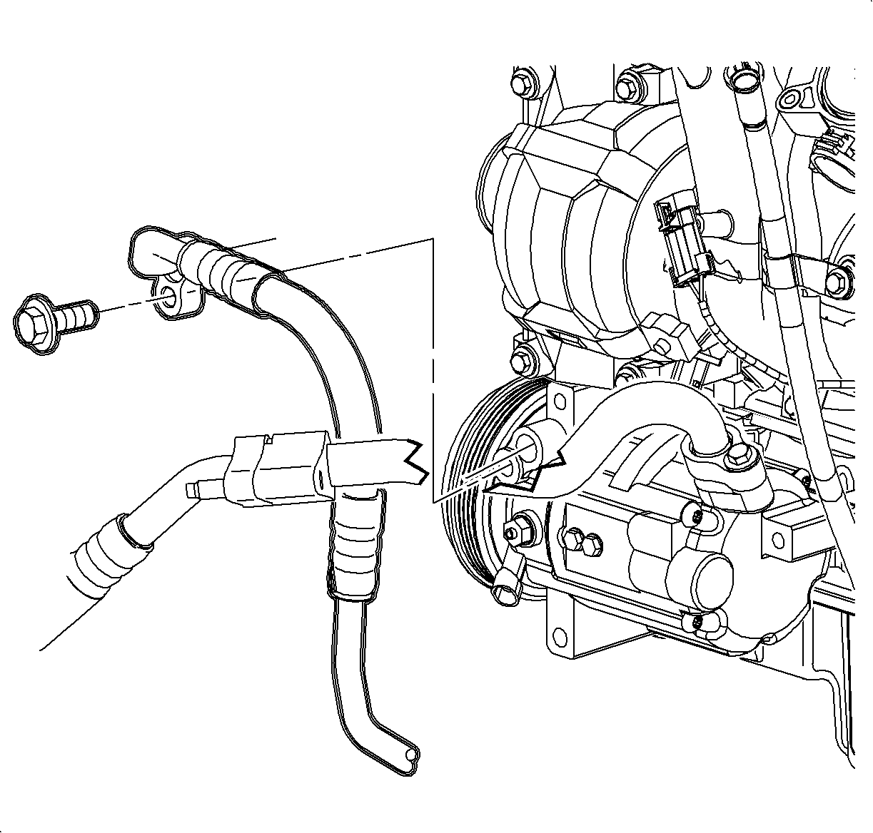
L61 Tightening Procedure
- Disconnect the negative battery cable.
- Tighten the suction pipe to the compressor bolt.
- Tighten the discharge line to the compressor bolt.
- Connect the negative battery cable.
- Affix the Campaign Completion Label on a clean and dry surface of the radiator core support, in an area clearly visible when the hood is raised. Refer to "Campaign Completion Label" in this bulletin.
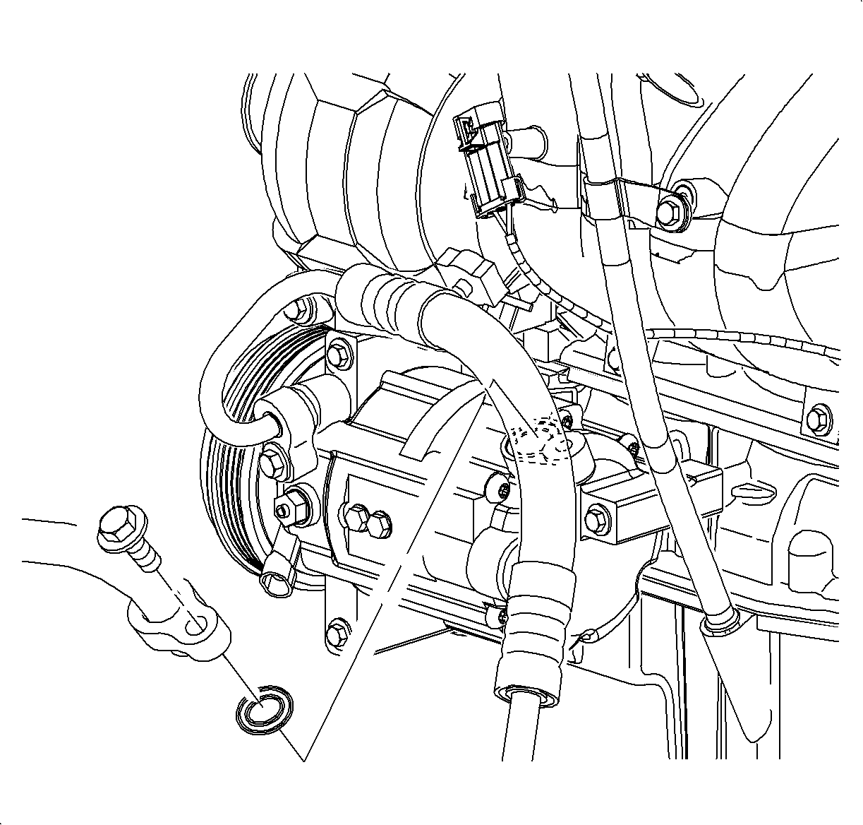
Tighten
Tighten the suction pipe to the compressor bolt
to 19 N·m (14 lb ft).
Tighten
Tighten the discharge line to the compressor bolt
to 19 N·m (14 lb ft).
Tighten
Tighten the battery terminal bolt to 17 N·m
(13 lb ft).
Important: Do NOT cover any existing underhood labels when affixing the Campaign Completion Label.
L81 Tightening Procedure
- Disconnect the negative battery cable.
- Tighten the suction pipe to the compressor bolt.
- Raise the vehicle.
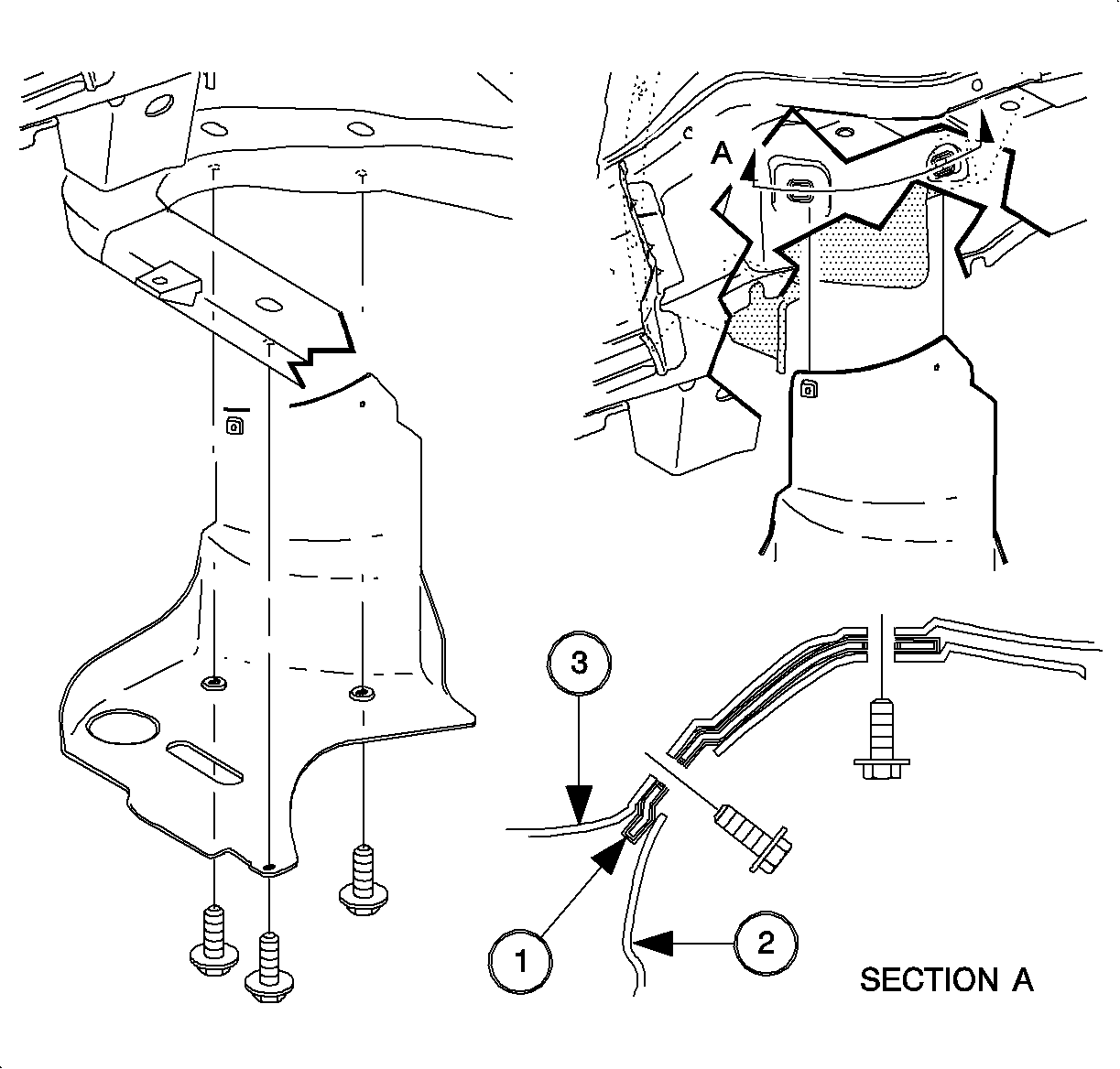
- Remove the right front lower splash shield.
- Tighten the discharge line to the compressor bolt.
- Install the right front lower splash shield and the bolts.
- Lower the vehicle.
- Connect the negative battery cable.
- Affix the Campaign Completion Label on a clean and dry surface of the radiator core support, in an area clearly visible when the hood is raised. Refer to "Campaign Completion Label" in this bulletin.
Tighten
Tighten the suction pipe to the compressor bolt
to 19 N·m (14 lb ft).
Caution: Properly support and position the vehicle on the hoist. To help avoid personal injury when a vehicle is on a host, provide additional support for the vehicle on the opposite end from which you are removing components.
Tighten
Tighten the discharge line to the compressor bolt
to 19 N·m (14 lb ft).
Tighten
Tighten the right front lower splash shield bolt
to 5 N·m (44 lb in).
Tighten
Tighten the battery terminal bolt to 17 N·m
(13 lb ft).
Important: Do NOT cover any existing underhood labels when affixing the Campaign Completion Label.
L61 Service Procedure
- Disconnect the negative battery cable.
- Recover the refrigerant using an approved refrigerant recovery system. Measure the amount of oil removed during the recovery procedure and record.
- Remove the suction pipe to the compressor bolt.
- Remove the suction pipe and the seal washer from the compressor.
- Install a new seal washer and a new bolt on the suction pipe.
- Install the suction pipe to the compressor and hand start the bolt.
- Remove the discharge line and the seal washer from the compressor.
- Install a new seal washer and a new bolt on the discharge line.
- Install the discharge line to the compressor and hand start the bolt.
- Connect the negative battery cable.
- Evacuate, recharge, and leak test the A/C system.
- Affix the Campaign Completion Label on a clean and dry surface of the radiator core support, in an area clearly visible when the hood is raised. Refer to "Campaign Completion Label" in this bulletin.
Important: Verify the purity of the refrigerant with a purity identifier before recovery.

Caution: Do NOT remove the hoses or the lines before the system is fully discharged.
Notice: Do NOT lubricate the seal washers.
Tighten
Tighten the suction pipe to the compressor bolt
to 19 N·m (14 lb ft).

Tighten
Tighten the discharge line to the compressor bolt
to 19 N·m (14 lb ft).
Tighten
Tighten the battery terminal bolt to 17 N·m
(13 lb ft).
Important: Do NOT cover any existing underhood labels when affixing the Campaign Completion Label.
L81 Service Procedure
- Disconnect the negative battery cable.
- Recover the refrigerant using an approved refrigerant recovery system. Measure the amount of oil removed during the recovery and record.
- Remove the battery heat shield.
- Disconnect the front upper oxygen sensor connector and remove the wire harness from the retaining clips.
- Raise the vehicle.
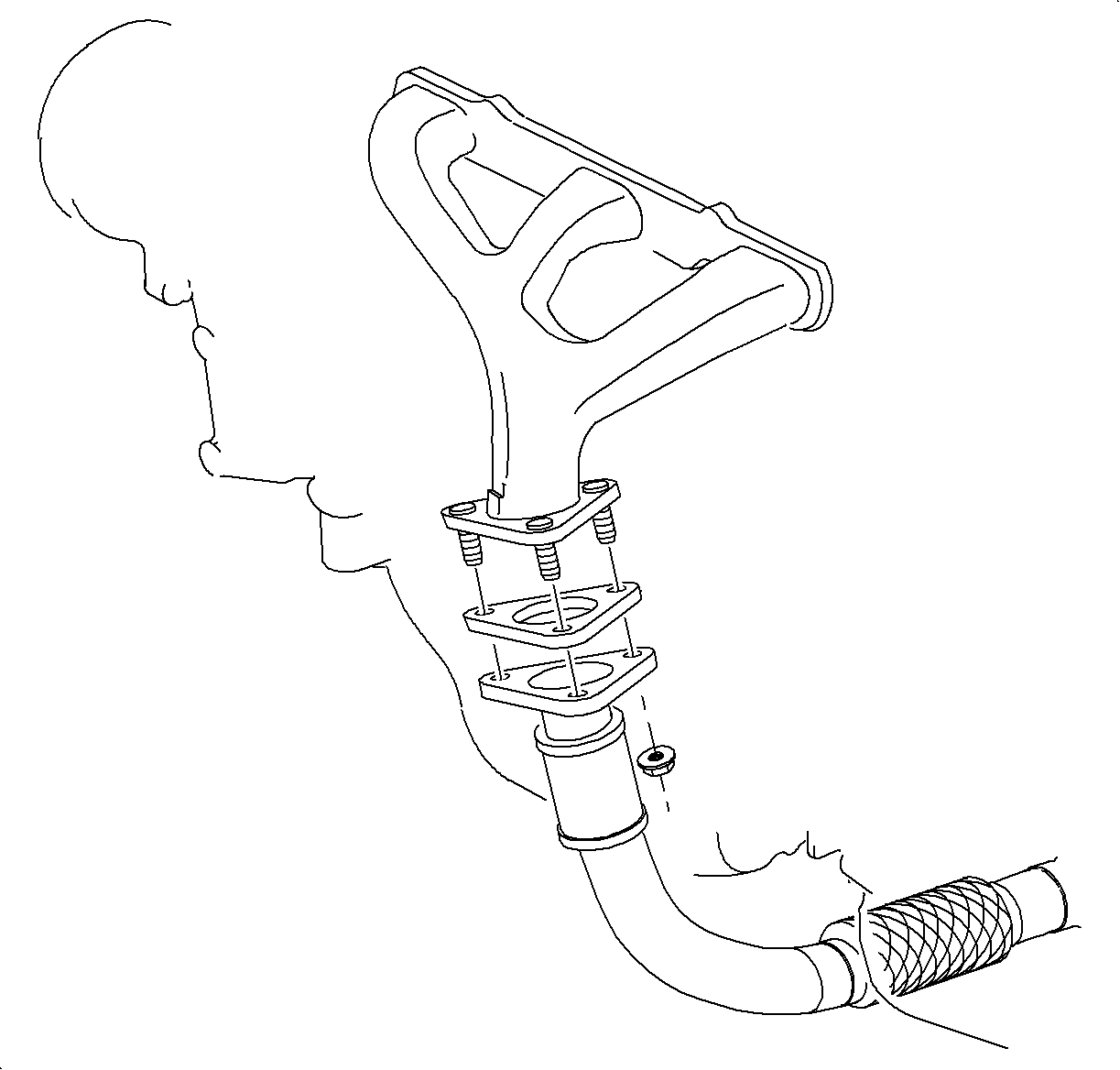
- Remove the exhaust manifold pipe to the exhaust manifold nuts.
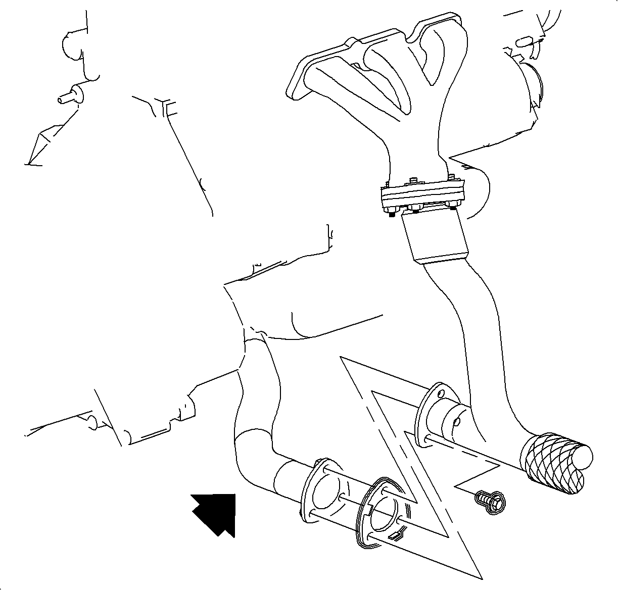
- Remove the front exhaust manifold pipe to the rear exhaust manifold pipe attachment bolts.
- Remove the front exhaust pipe with the oxygen sensor attached.
- Remove the right front lower splash shield.
- Remove the suction (inlet) pipe to the compressor and remove the suction pipe.
- Install a new seal washer and a new fastener to the suction (inlet) pipe.
- Install the suction (inlet) pipe to the compressor and hand start the bolt.
- Remove the discharge (outlet) line from the compressor.
- Install a new seal washer and a new fastener to the discharge (outlet) line.
- Install the discharge (outlet) line to the compressor and hand start the bolt.
- Position the gasket on the exhaust manifold pipe.
- Position the front exhaust manifold pipe to the vehicle.
- Install the exhaust manifold pipe to the exhaust manifold nuts.
- Position the gasket between the front and the rear exhaust manifold pipes.
- Install the front exhaust manifold pipe to the rear exhaust manifold pipe bolts and tighten.
- Tighten the exhaust manifold pipe to the exhaust manifold nuts.
- Route the oxygen sensor wiring to the top of the engine.
- Install the right front lower splash shield bolts.
- Lower the vehicle.
- Connect the oxygen sensor connector and route the wiring into the clips.
- Install the battery heat shield.
- Connect the negative battery cable.
- Evacuate, recharge, and leak test the A/C system.
- Affix the Campaign Completion Label on a clean and dry surface of the radiator core support, in an area clearly visible when the hood is raised. Refer to "Campaign Completion Label" in this bulletin.
Important: Verify the purity of the refrigerant with a purity identifier before recovery is recommended.
Caution: Do NOT remove the hoses or the lines before the system is fully discharged.
Caution: Properly support and position the vehicle on the hoist. To help avoid personal injury when a vehicle is on a host, provide additional support for the vehicle on the opposite end from which you are removing components.


Notice: Do NOT lubricate the seal washers.
Tighten
Tighten the suction pipe to the compressor bolt
to 19 N·m (14 lb ft).
Notice: Do NOT lubricate the seal washers.
Tighten
Tighten the discharge line to the compressor bolt
to 19 N·m (14 lb ft).
Notice: Do not tighten fasteners.


Tighten
Tighten the exhaust manifold pipe bolts to 20 N·m
(15 lb ft).
Tighten
Tighten the exhaust manifold pipe to the exhaust
manifold nuts to 30 N·m (22 lb ft).

Tighten
Tighten the right splish shield to body bolts to
5 N·m (44 lb in).
Tighten
Tighten the battery terminal bolt to 17 N·m
(13 lb ft).
Important: Do not cover any existing underhood labels when affixing the Campaign Completion Label.
Campaign Completion Label
Upon completion of the campaign, a Campaign Identification Label and a Clear Protective Cover should be affixed on a clean, dry surface of the radiator core support in an area clearly visible when the hood is raised. Each label provides a space to print in ink (or type) the campaign number (00C10) and the five (5) digit facility code of the Retailer performing the campaign service.
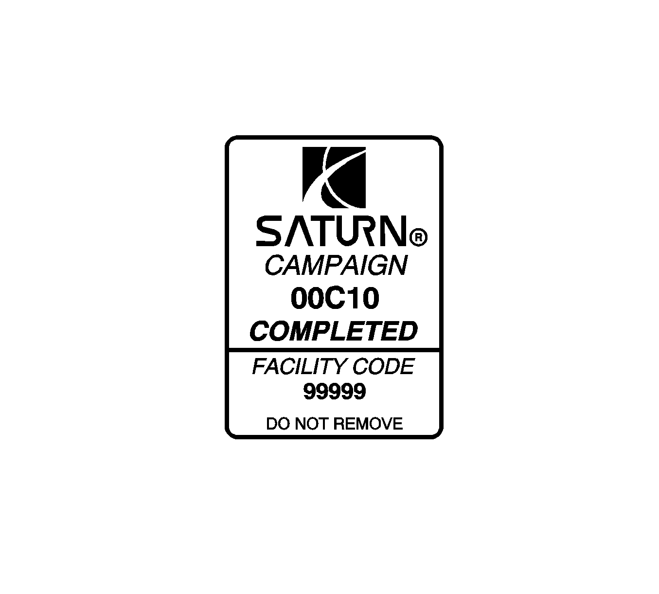
As a reminder, additional labels may be ordered from Saturn publications (1-800-828-2112, prompt 3, Item # S03 00013A for the Campaign Completion Label and Item # S03 00013B for the Clear Protective Cover ).
Credit
1. To receive credit, submit a claim with the information below:
Repair Information | Parts Allow. | Sale Type | Case Type | Labor Op | Labor Hours | Admin. Hours** | |
|---|---|---|---|---|---|---|---|
To Perform the Performance Test, Inspect and Re-tighten the Suction Pipe and Discharge Line Bolts | * | WC | VC | V0571 | -- | 0.1 | |
| -- | -- | -- | -- | 0.6 | -- | |
| -- | -- | -- | -- | 0.8 | -- | |
To Perform the Performance Test, Inspect and Replace the Suction Pipe and Discharge Line Bolts, including new Seal Washers | * | WC | VC | V0572 | -- | 0.1 | |
| -- | -- | -- | -- | 1.5 | -- | |
| -- | -- | -- | -- | 2.0 | -- | |
If additional A/C procedures are performed, refer to the appropriate Electronic Labor Time Guide for the correct Labor Operation Code and Time.
2. To receive credit for loaner/rental car costs incurred while owner awaits campaign repair or other goodwill expenses, submit a claim with the information below:
Repair Performed | Sale Type | Case Type | Labor Op | Net Item Amount | Net Item Code | # Days Rental |
|---|---|---|---|---|---|---|
Loaner Reimbursement | WC | VC | Z4116 | *** | C | **** |
Other/Goodwill | WC | VC | Z4117 | *** | R | N/A |
3. Retailers are empowered to use good judgement regarding loaner/rental cars or any other goodwill expenses deemed necessary. It will not be necessary to call the Saturn Customer Assistance Center for authorization of goodwill. The Goodwill Worksheet (printed towards the back of this bulletin) must be used to document goodwill expenses. The completed Goodwill Worksheet must be attached to the hard copy of the CSO. Retailers are to make sufficient copies of the blank Goodwill Worksheet to document goodwill expenses.
4. Check your Saturn SERVICELINE.XL Claim Memorandum daily. Remember to code the claim as a WC sale type and VC case type. Contact your field representative if you need assistance.
5. All labor operations claimed in this bulletin must be submitted on individual (unrelated) CSO lines. Refer to the Customer Service Order Preparation Manual for details on Product Campaign Claim Submission.
* The parts allowance should be the sum total of the current SSPO Retailer net price plus 30% of all parts required for the repair.
** Campaign administrative allowance.
*** Net amount must be submitted as a miscellaneous sale...Loaner reimbursement not to exceed $30/day.
**** Enter number of days vehicle was rented...Not to exceed 1 day.
00-C-10 GOODWILL WORKSHEET
As stated in the "Credit" section of this bulletin, Retailers are empowered to use good judgement regarding loaner/rental cars or other goodwill expenses that might become necessary for customer satisfaction.
Complete this worksheet and attach it to the hard copy of the Customer Service Order (CSO) to document all campaign goodwill claims submitted to Saturn.
VIN #
A. Vehicle Loaner/Rental Allowance Explanation: | $ | ||||
| |||||
| |||||
| |||||
Repair Performed | Sale Type | Case Type | Labor OP | Net Item Code | # Days Rental |
Loaner Reimbursement | WC | VC | Z4116 | C | * |
* Not to exceed $30/day for 1 day | |||||
| |||||
| |||||
| |||||
B. Other/Goodwill Allowance Explanation (Specify what was done and why): | $ | ||||
| |||||
| |||||
| |||||
Repair Performed | Sale Type | Case Type | Labor OP | Net Item Code | # Days Rental |
Other Goodwill | WC | VC | Z4117 | R | N/A |
| |||||
| |||||
| |||||
Authorized Retailer Signature | |||||
(Please copy this form as necessary) | |||||
Dear Saturn Owner:
Saturn has decided that certain 2000 model year L-Series vehicles were produced with improperly tightened suction pipe and discharge line bolts at the air conditioning compressor. If either bolt is not adequately tightened, a refrigerant leak will occur, and the air conditioner will not blow cold air.
To prevent the possibility of this condition occurring, Retailers will conduct an air conditioner system performance test and tighten the suction pipe and discharge line bolts. If a leak is found, Retailers will replace the suction pipe and discharge line bolts and seal washers and evacuate and recharge the air conditioning system.
What Saturn will do
Saturn will conduct an air conditioner performance test, tighten and/or replace the affected bolts, and evacuate and recharge your air conditioner system as necessary at no charge to you.
What you should do
Contact your Saturn Retailer to arrange to have your air conditioner system evaluated. The inspection/testing procedure will take approximately 45 minutes. However, if a leak is found the repair could take an additional 1½ hours. Additional time may be required for paperwork and processing.
Should your retailer be unable to schedule a service date within a reasonable time, please contact the Saturn Customer Assistance Center at 1-800-553-6000 prompt 3, or for the hearing impaired, 1-800-833-6000. We will assist you and the Retailer in getting your car serviced.
Again, we sincerely regret any inconvenience or concern this situation may cause you. We want you to know that we will do our best, throughout your ownership experience, to ensure that your Saturn provides you many miles of enjoyable driving.
Sincerely,
Saturn Corporation
00-C-10
