Circuit Description
Class II serial data is a 0-7 volt variable pulse width message scheme (logic 0's and logic 1's) used to communicate information between modules and for communication to an off-board scan tool. Contained in each module memory is a list of serial data messages and default actions taken by the module if one of the important messages is not received. One of the most important messages is the state of health (SOH) message used to inform each module that other modules on the Class II link are functioning correctly.
Each module on the Class II link must first "learn" all modules connected to the Class II link every time the ignition is turned On. Each message that a module sends out on the link contains a source identifier used to identify where the information came from. Once a module receives information, it will store the attached controller ID. If this same information is not received later in the ignition cycle, lost communications with a specific controller DTC will set. DTC U1016 sets when a controller does not receive specific information from the powertrain control module (PCM) after it had already learned its source ID in that ignition cycle.
Conditions for Setting the DTC
DTC U1016 will set if the body control module (BCM) or sensing and diagnostic module (SDM) lost Class II communications with the PCM when:
| • | The condition exists for longer than 3 seconds. |
| • | The BCM or SDM already learned the PCM source identifier in the ignition cycle. The PCM had initially communicated with both the SDM and BCM when the ignition was first turned On. |
| • | The ignition is On. |
DTC U1016 diagnostic runs continuously with ignition On.
DTC U1016 is a type C DTC.
Diagnostic Aids
Important: If the engine control module (ECM) is not communicating over the CAN link to the BCM, the SDM will set U1016 (L81).
To locate an intermittent problem, use a scan tool to monitor PCM located under DIAGNOSTIC CIRCUIT CHECK---CLASS II MESSAGE MONITOR with the ignition On and the engine Off. INACTIVE will be displayed if the PCM is not communicating on the Class II link.
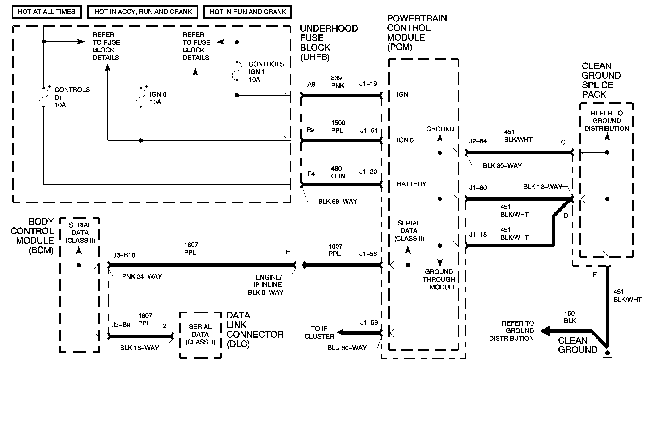
If an intermittent loss of battery power to the PCM via CKT 480 exists, scan tool communication with the PCM will be lost and the engine will stall and not restart.
If an intermittent loss of ignition power to the PCM via CKT 839 exists, scan tool communication with the PCM will NOT be lost; however, the engine will stall and not restart.
If CKT 1500 is open, communications with the PCM will exist and the engine will start and run normally.
An independent open is any of the three 451 circuits between the PCM and ground splice pack will NOT cause a communication problem with the PCM since all three 451 circuits are tied together in the PCM.
A loose ground splice pack or open in CKT 451 from the splice pack to the chassis ground will cause a lack of PCM communication and the engine will stall and not restart.

