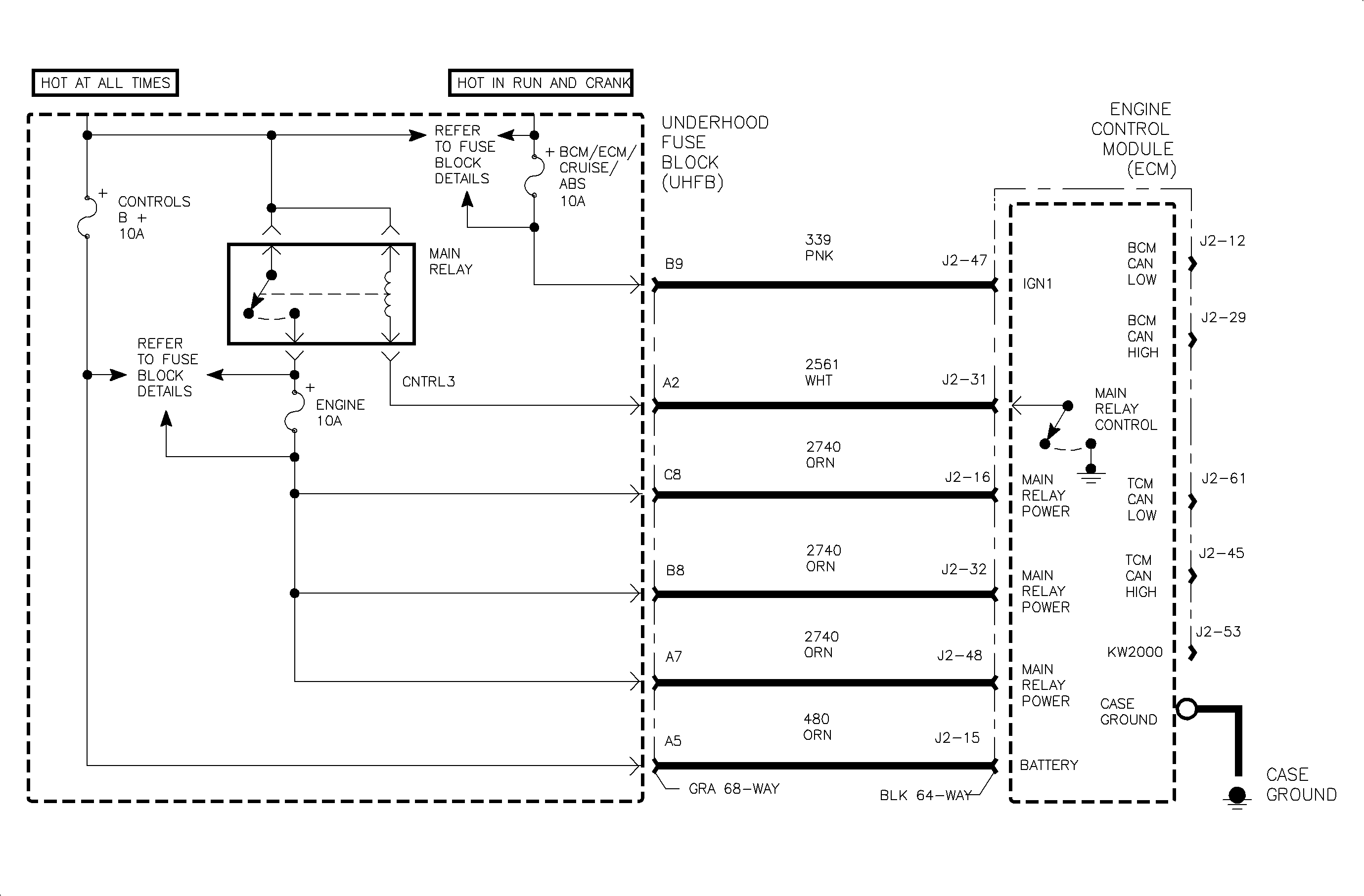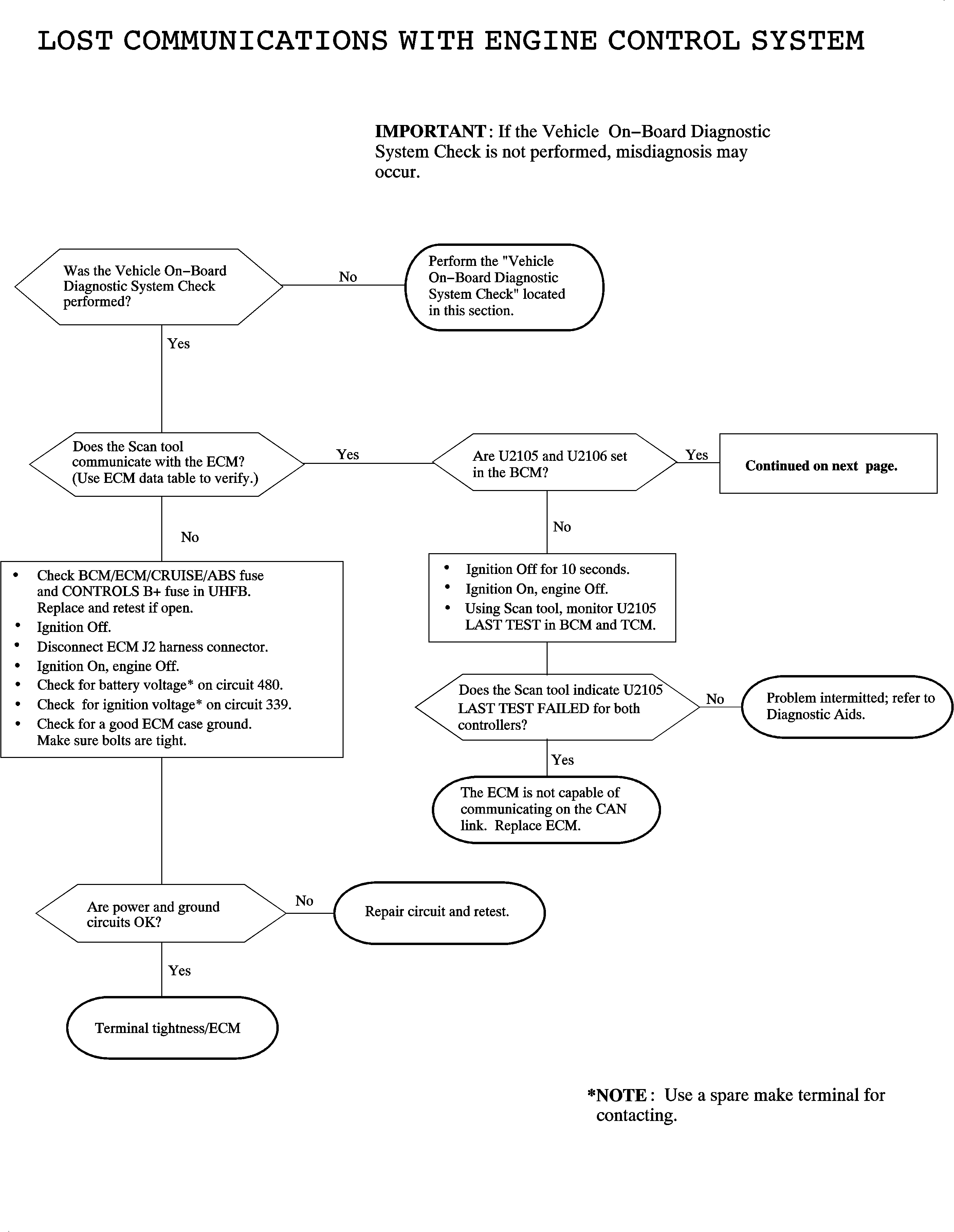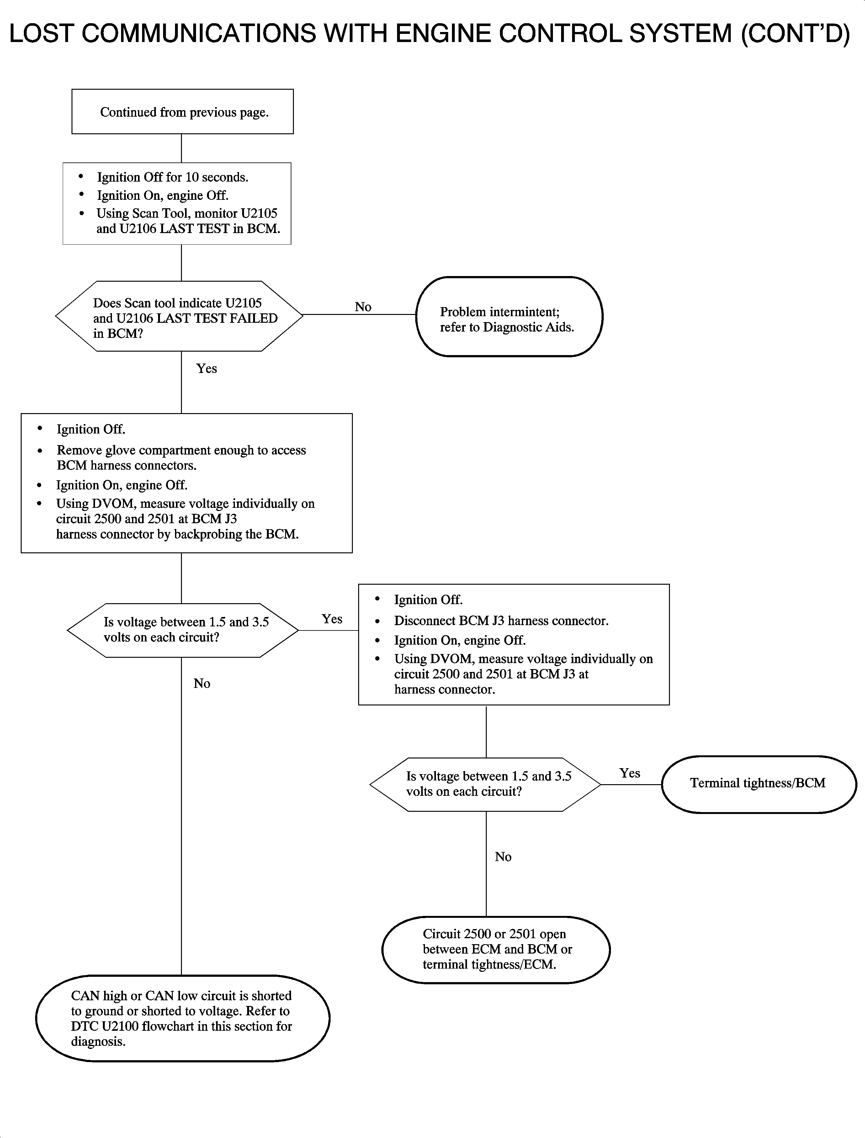
Circuit Description
The engine control module (ECM), transaxle control module (TCM) and body control module (BCM) communicate normal mode messages over the controller area network (CAN) link CKTs 2500 and 2501. Each controller on the CAN link uses a variable pulse width modulated square wave consisting of logic "0s" and logic "1s". A logic 0 is denoted as CKT 2501 at 1.5 volts with CKT 2500 at 3.5 volts resulting in a difference of 2 volts across the circuits. A logic "0" is denoted as both CKTs 2500 and 2501 at 2.5 volts resulting in a difference of 0 volts across the circuits.
State of health messages are sent from each CAN controller on the link when the ignition is turned On as well as during normal vehicle operation. These messages allow the BCM, ECM and TCM to know that each controller on the link is functioning correctly. The ECM monitors the CAN link for low and high voltage faults. All controllers on the CAN link monitor each others messages and can set a DTC if information is not received. DTC U2105 sets when a specific controller has lost communications with the ECM.
Conditions for Setting the DTC
DTC U2105 will set if the BCM or TCM lost CAN communications with the ECM when:
| • | The condition exists for longer than 2 seconds for TCM and 3 seconds for BCM. |
| • | The ignition is On. |
DTC U2105 diagnostic runs continuously with ignition On.
DTC U2105 is a type A DTC for TCM.
DTC U2105 is a type C DTC for BCM.
Diagnostic Aids
Important: If DTC U2100 is also set in the ECM, diagnose that DTC first. If a circuit fault occurs on the CAN link, the BCM and/or TCM will set DTC U2105.
Inspect the ECM mounting bolts for tightness and corrosion.
The TCM sends the ECM vehicle speed over the CAN link. The ECM sends the BCM fuel level over the link as well. If the ECM is not communicating on the CAN link, vehicle speed in Scan tool ECM DATA TABLE will read 0 km/h (0 mph) with the vehicle moving and the fuel gauge on the I/P cluster will read EMPTY. This may be used for intermittent diagnosis.
With ignition On, each CAN high or CAN low circuit should have between 1.5-3.5 volts measuring into a control module no matter how many modules are left connected.
An open anywhere in the CAN link will result in at least one controller not communicating.


