Tools Required
| • | J 38122-A Crankshaft Pulley Holder |
| • | SA9805E Fuel Line Disconnect Set |
Removal Procedure
- Disconnect the negative battery cable.
- Remove the intake manifold. Refer to Intake Camshaft, Bearing Cap, and Lash Adjuster Removal procedure in this section.
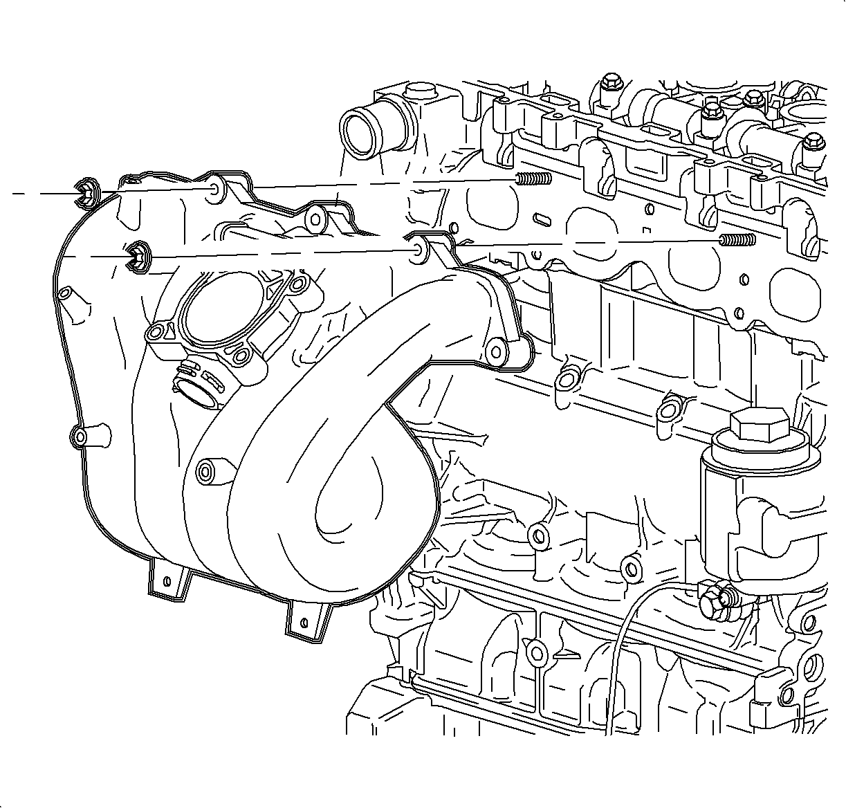
- Remove the exhaust manifold flange bolts.
- Remove the coolant reservoir cap.
- Raise the vehicle.
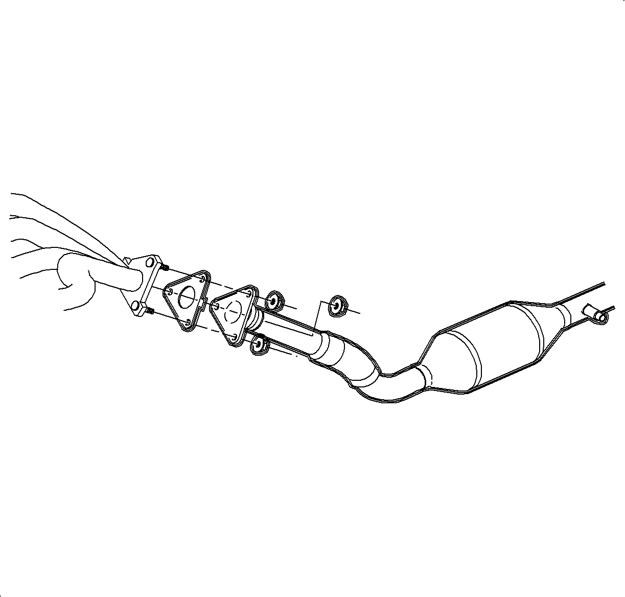
- Remove the exhaust manifold down pipe to catalytic convertor bolts.
- Disconnect the exhaust down pipe from the exhaust manifold flange studs and secure the exhaust pipe to the under-carriage.
- Drain the coolant at the radiator and at the water pump drain plug.
- Lower the vehicle.
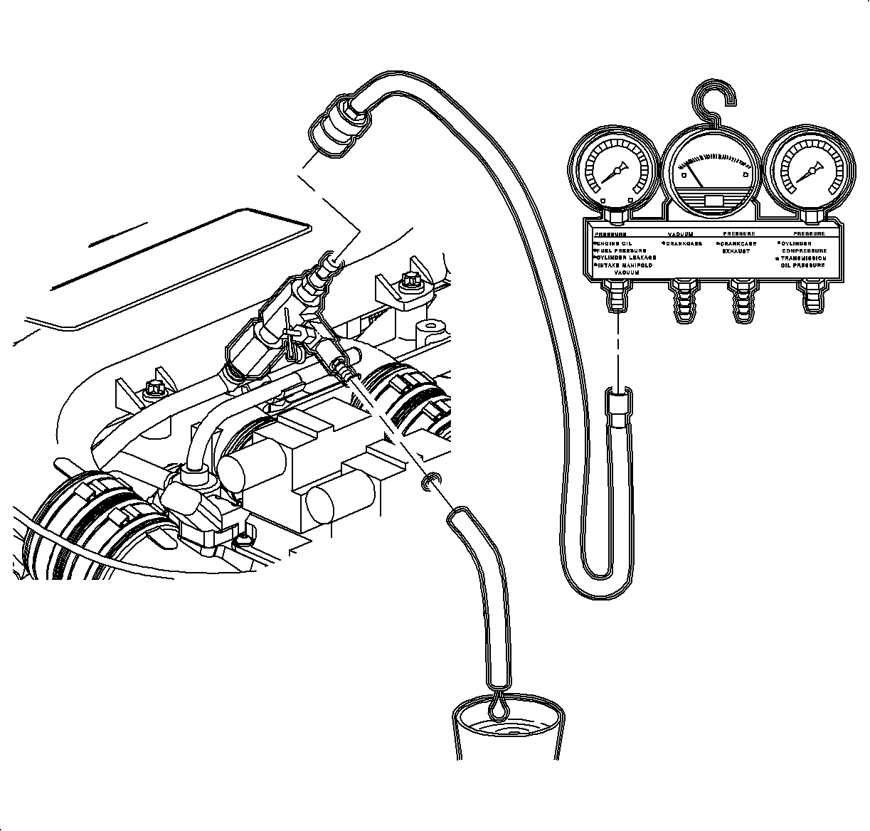
- Relieve the fuel system pressure. Refer to Fuel System Diagnosis procedure in the "Fuel System" section of this service manual.
- Remove the fuel line bracket bolts.
- Disconnect the fuel lines at the quick disconnects using the SA9805E .
- Secure the lines away from the engine.
- Disconnect the A/C pressure switch electrical connection.
- Remove the crankcase vent hose from the camshaft cover.
- Remove the coolant air bleed hose at the coolant reservoir and remove from the bracket.
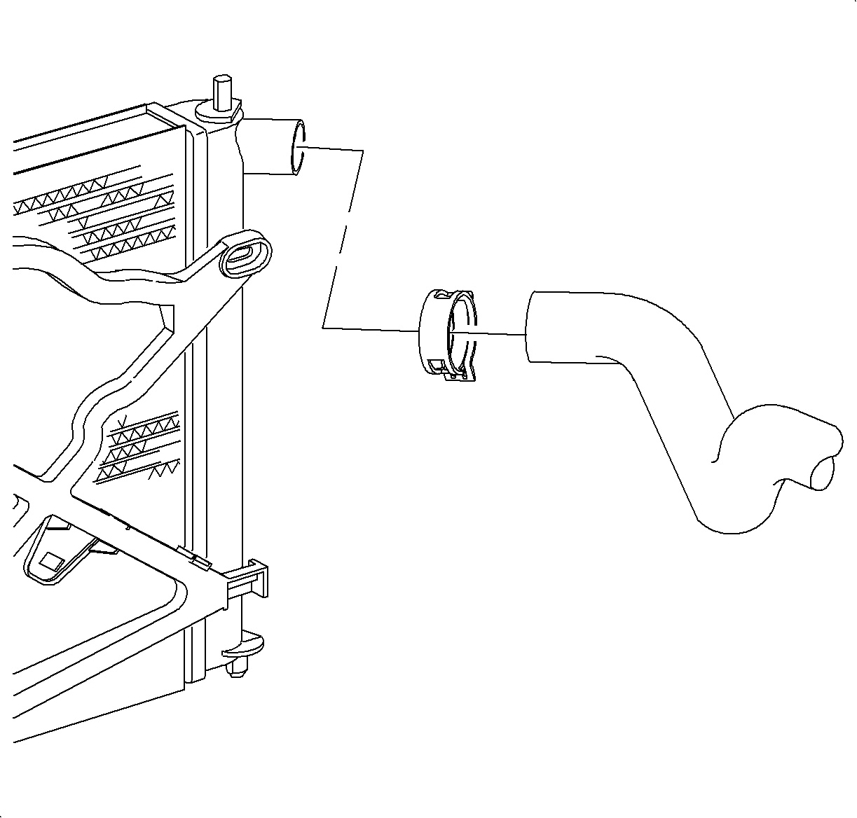
- Disconnect the upper radiator hose at the cylinder head.
- Disconnect the electrical connections.
- Remove all of the engine harness bracket fasteners and secure the harness away from the engine.
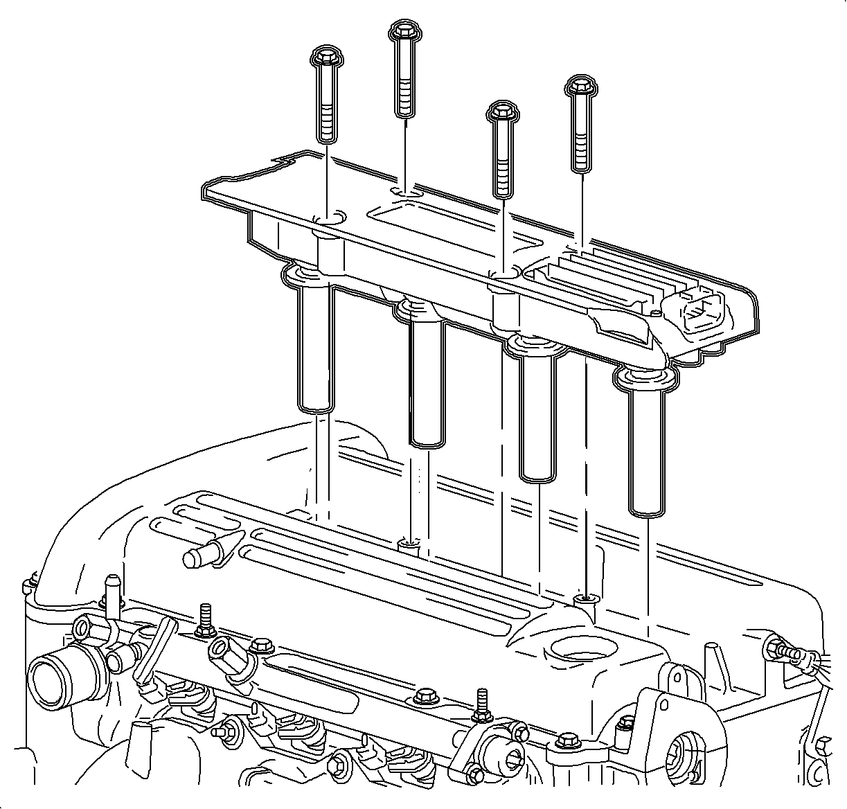
- Remove the ignition coil.
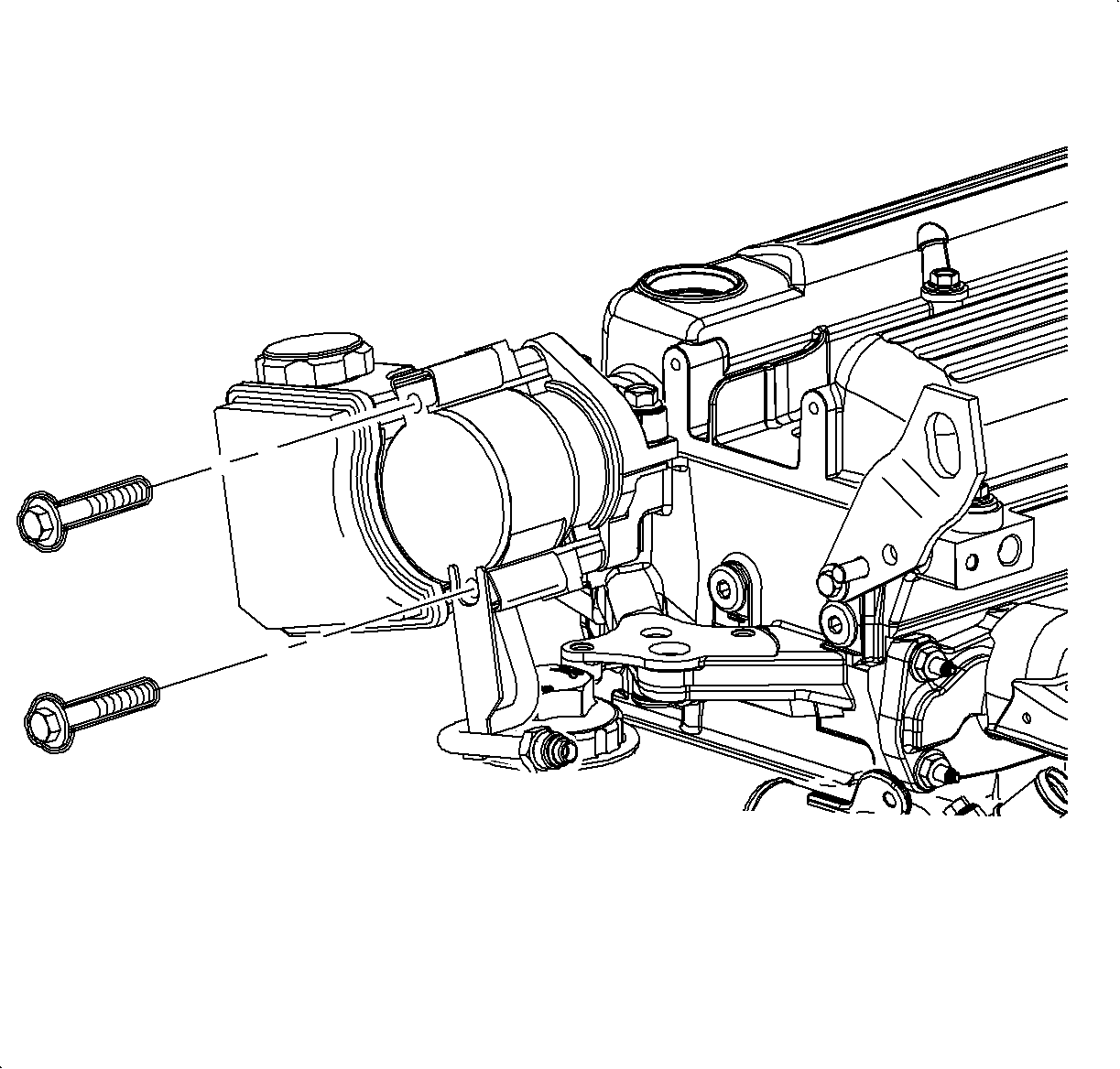
- Remove the power steering pump and secure away from the engine. Do not remove the hydraulic lines.
- Remove the camshaft cover ground strap.
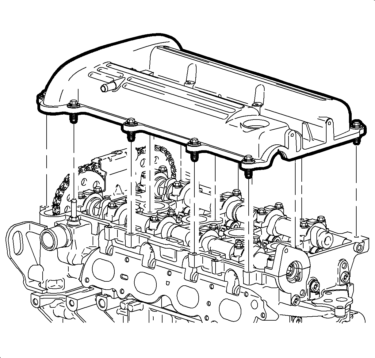
- Remove the camshaft cover bolts and remove the cover.
- Remove the upper timing chain guide.
- Remove the upper timing chain tensioner.
- Remove the camshaft sprocket bolts using a 24 mm open-end wrench to counter-hold the camshaft while loosening the bolts. Discard the bolts.
- Attach a medium size cable tie to the timing chain to prevent the chain from falling into the oil pan.
- Remove the camshaft sprockets.
- Remove the plug to gain access to the fixed timing chain guide bolt.
- Remove the fixed timing chain guide upper bolt only.
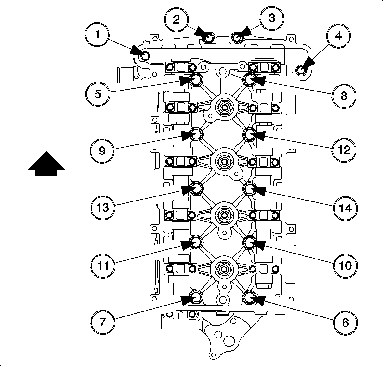
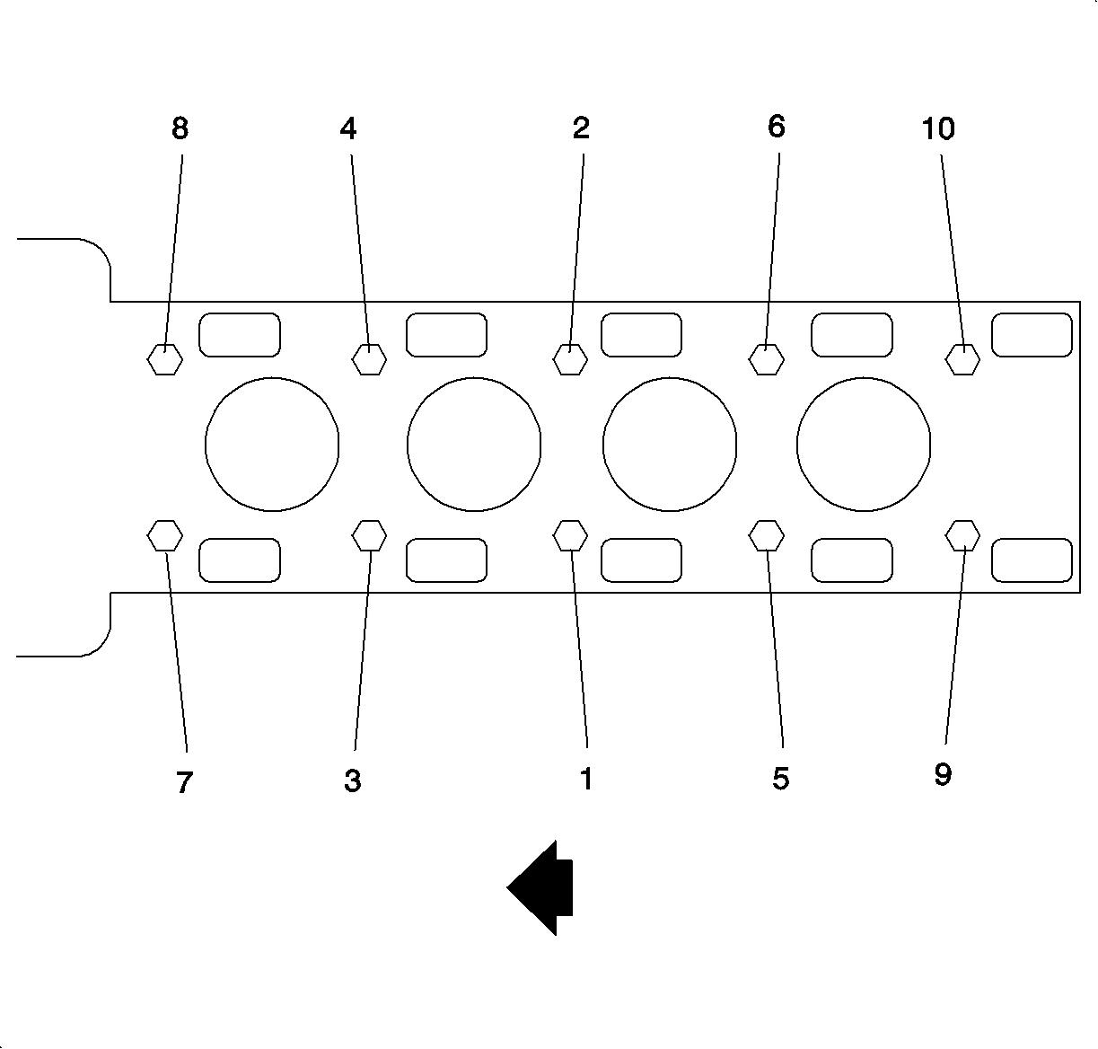
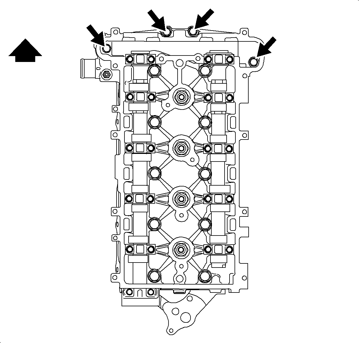
- Remove the cylinder head to block bolts using the loosening sequence.
- Lift the cylinder head from the dowels on the engine block and place the cylinder head on wooden blocks or a bench. If the cylinder head is difficult to lift off, use a pry bar at the designated pry points.
- Raise the vehicle.
- Remove the right front wheel.
- Remove the lower splash shield.
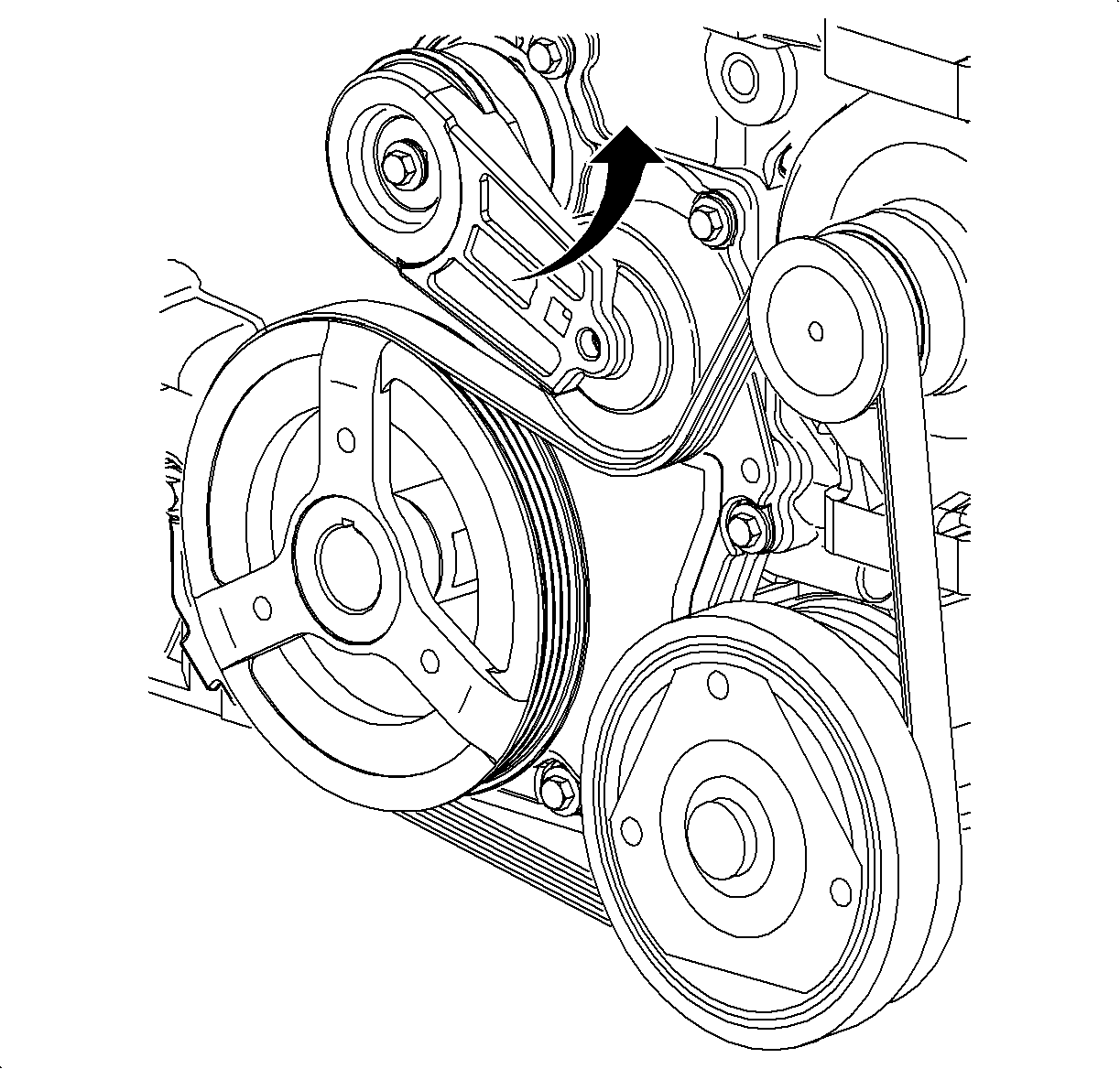
- Remove the accessory drive belt.
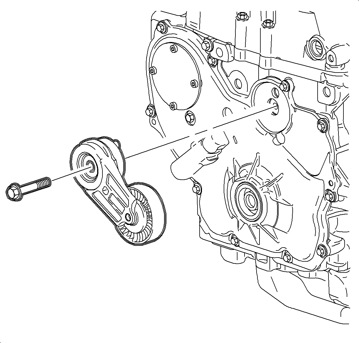
- Remove the accessory drive belt tensioner.
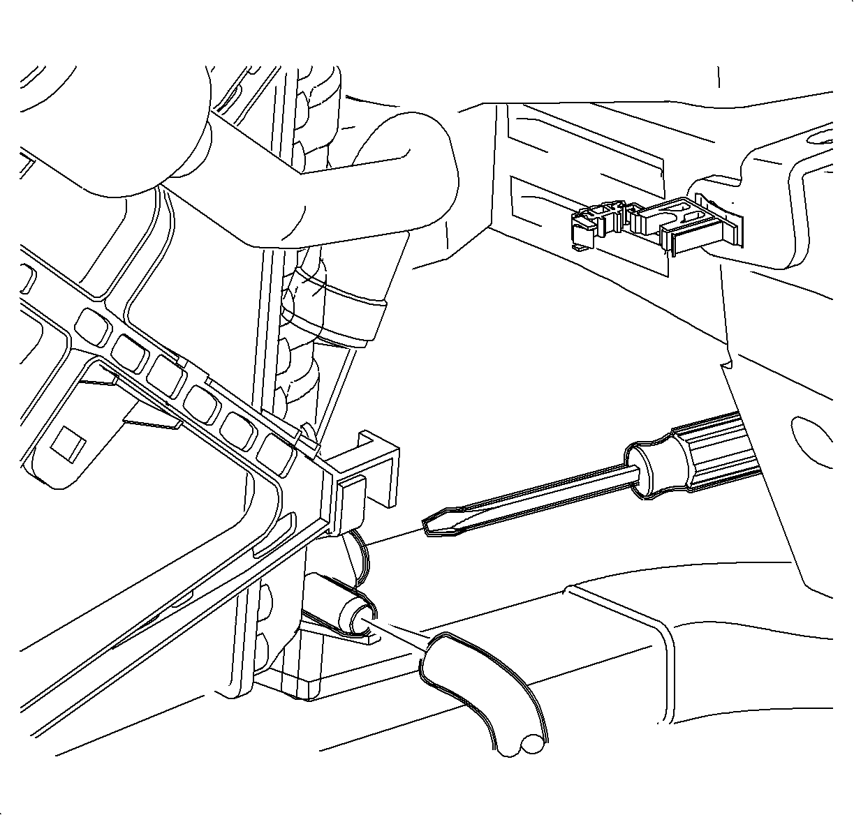
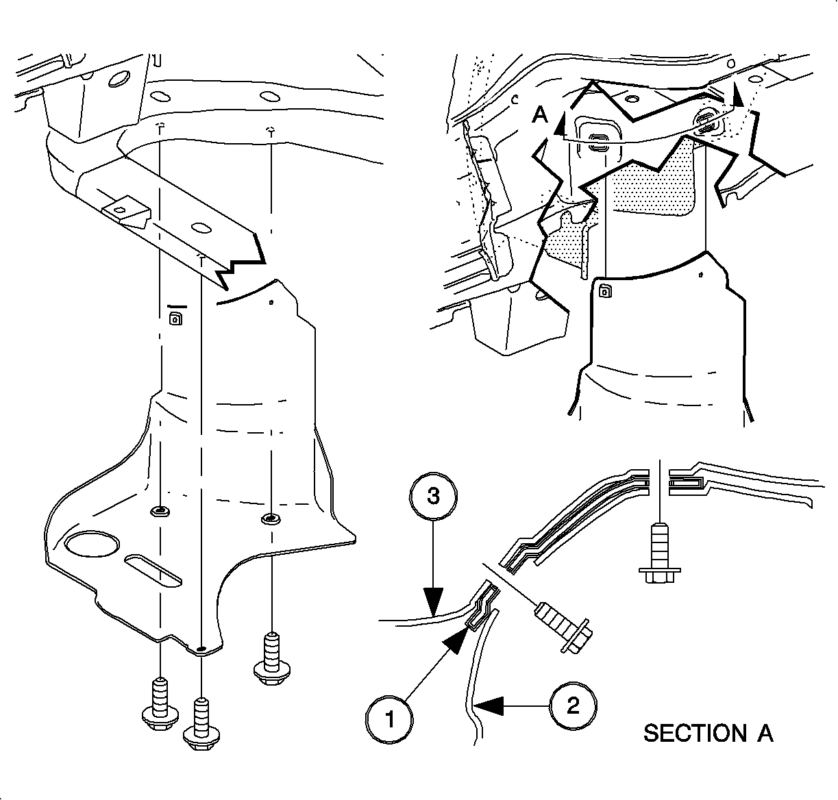
- Remove the suction liquid A/C line retaining clips from underneath the right side frame rail and position the line away to allow clearance to the crankshaft pulley bolt.
- Position the crankshaft 60° before top dead center (BTDC).
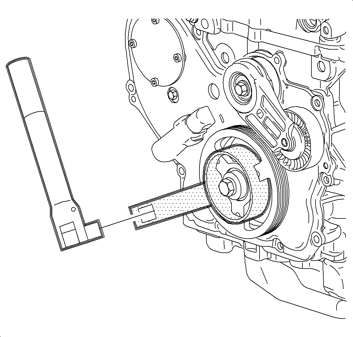
- Install the J 38122-A .
- Remove and discard the crankshaft damper pulley bolt.
- Remove the crankshaft pulley.
- Remove all front cover bolts except for the bolt that is blocked by the engine mount bracket.
- Loosen the water pump bolt. Do not remove at this time.
- Lower the vehicle.
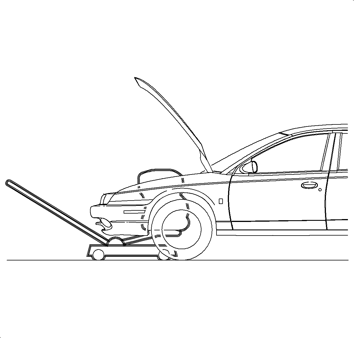
- Support the engine weight with the floor jack under the oil pan.
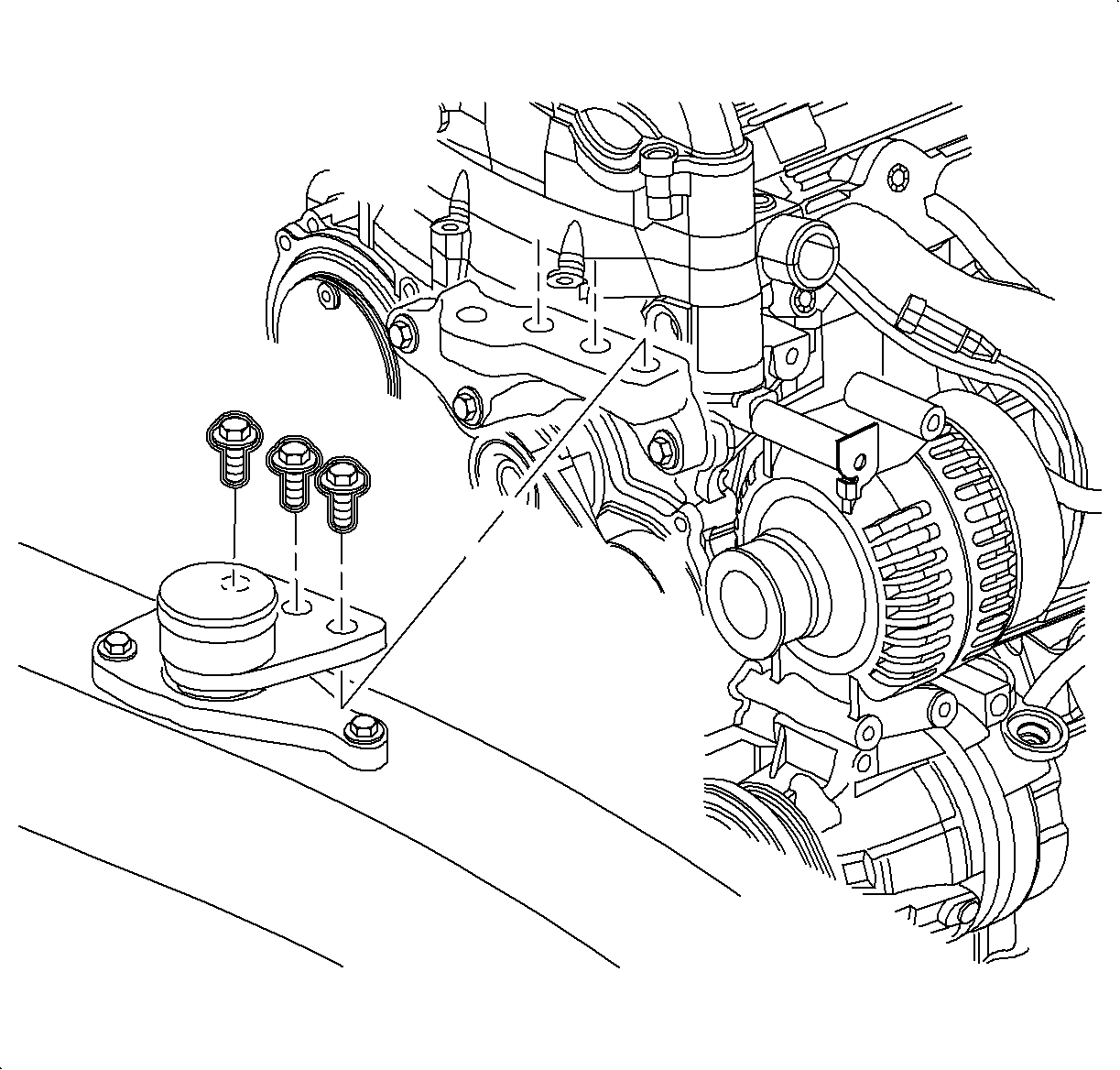
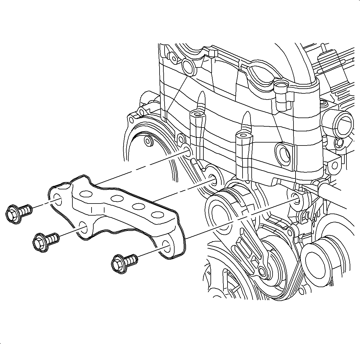
- Remove the right-hand engine mount to bracket bolts.
- Remove the engine mount to body bolts.
- Remove the engine mount from the vehicle.
- Remove the engine mount bracket to engine bolts.
- Remove the bracket from the vehicle.
- Lower the engine.
- Remove the crankshaft damper pulley and discard the bolt.
- Remove the upper front cover bolt, behind the engine mount.
- Raise the engine just enough to remove the water pump bolt.
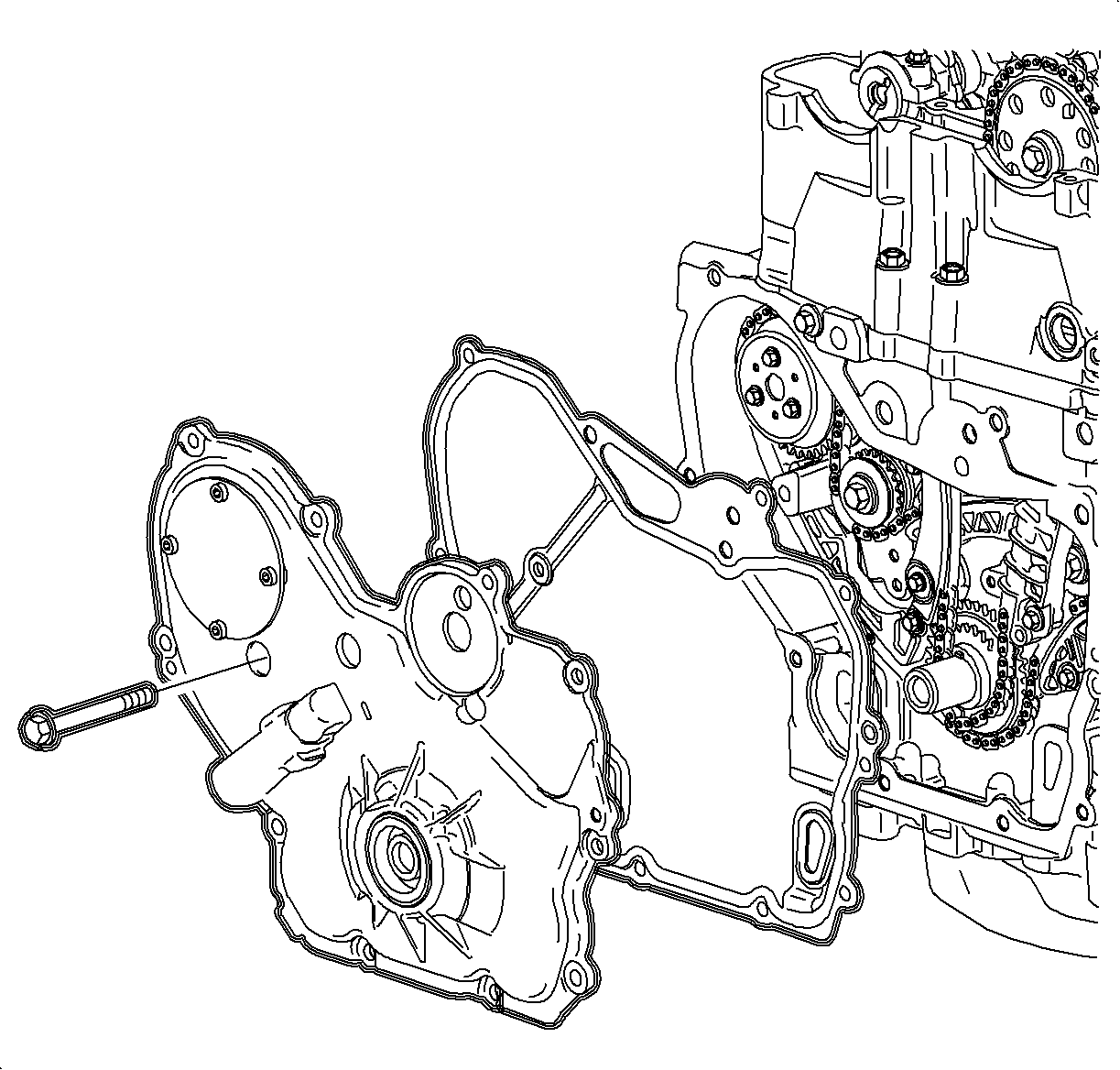
- Remove the front cover.
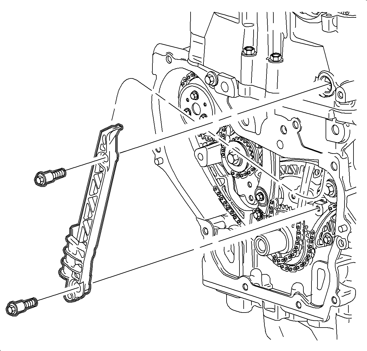
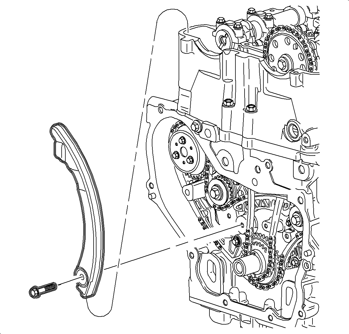
- Remove the adjustable timing chain guide.
- Remove the fixed timing chain guide, lower bolt.
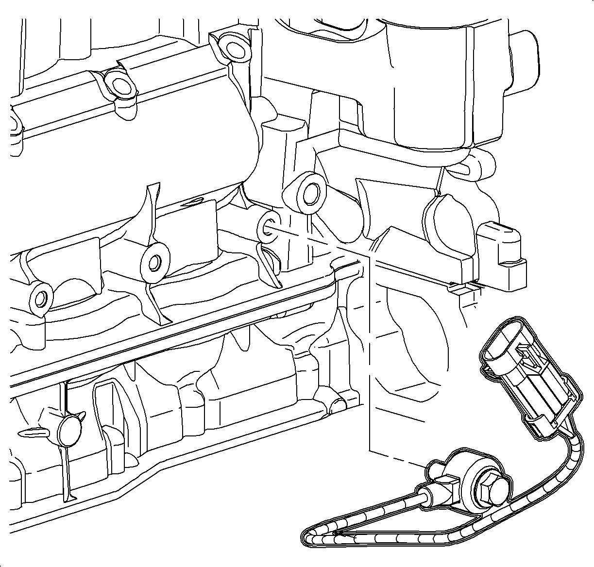
| 18.1. | Ignition coil |
| 18.2. | Knock sensor (connector only) |
| 18.3. | Coolant temperature sensor |
| 18.4. | Fuel injector harness |
| 18.5. | Front O2 sensor |
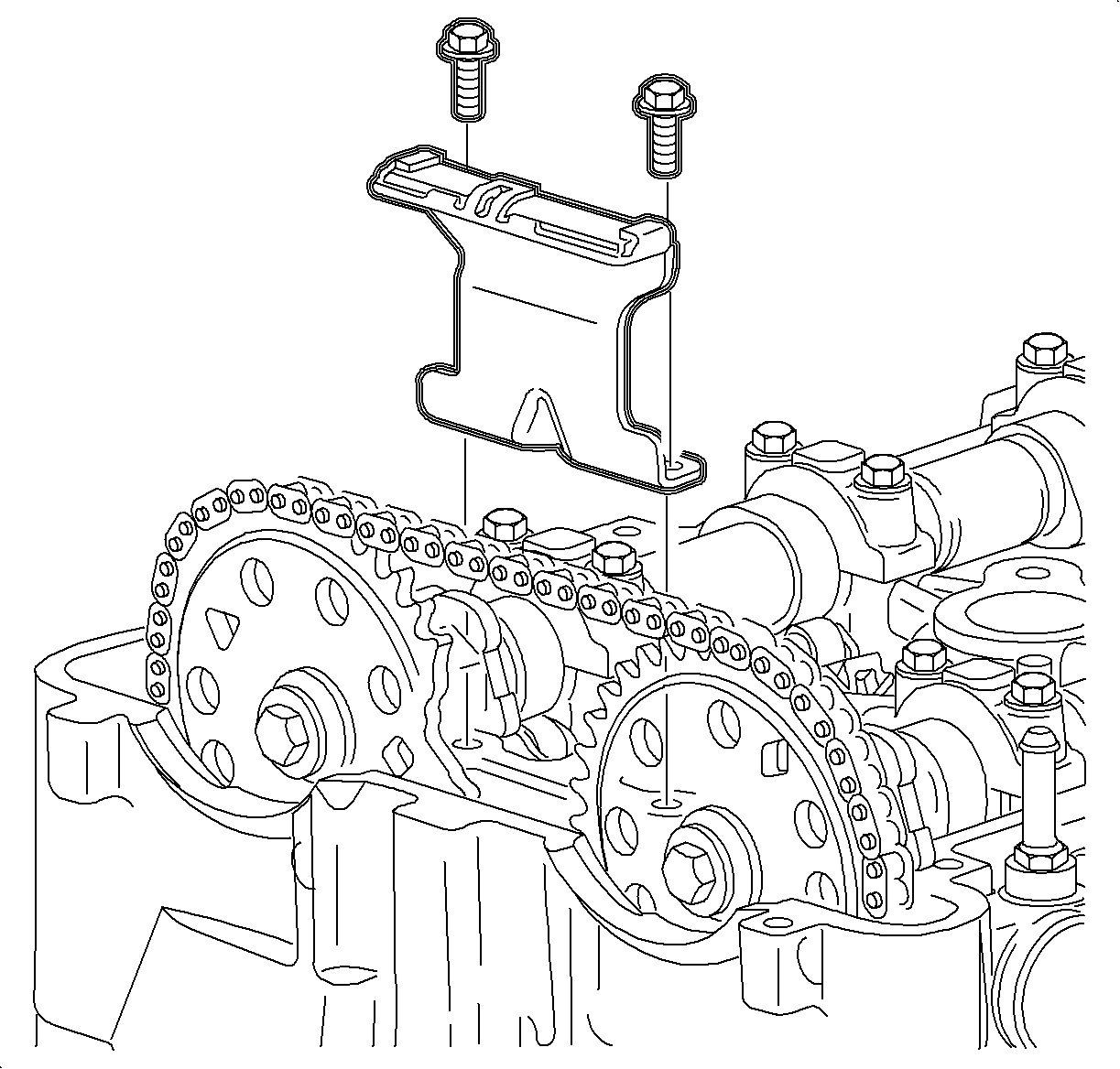
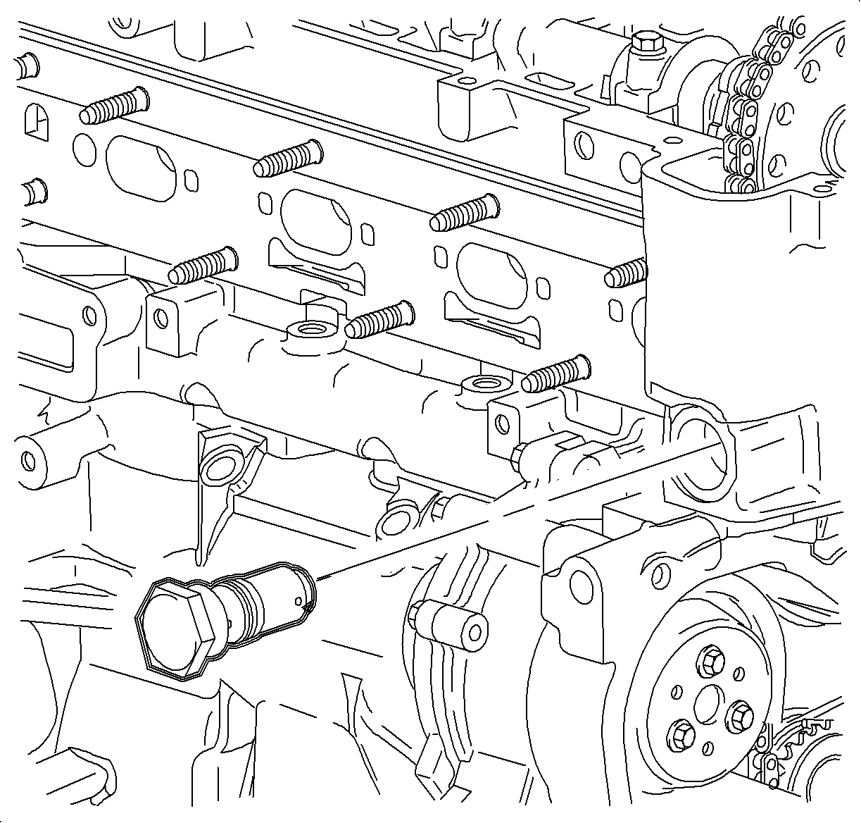
Important: The timing chain tensioner must be removed to unload the chain tension before the timing chain is removed. If it is not, the timing chain may become misaligned and difficult to remove.
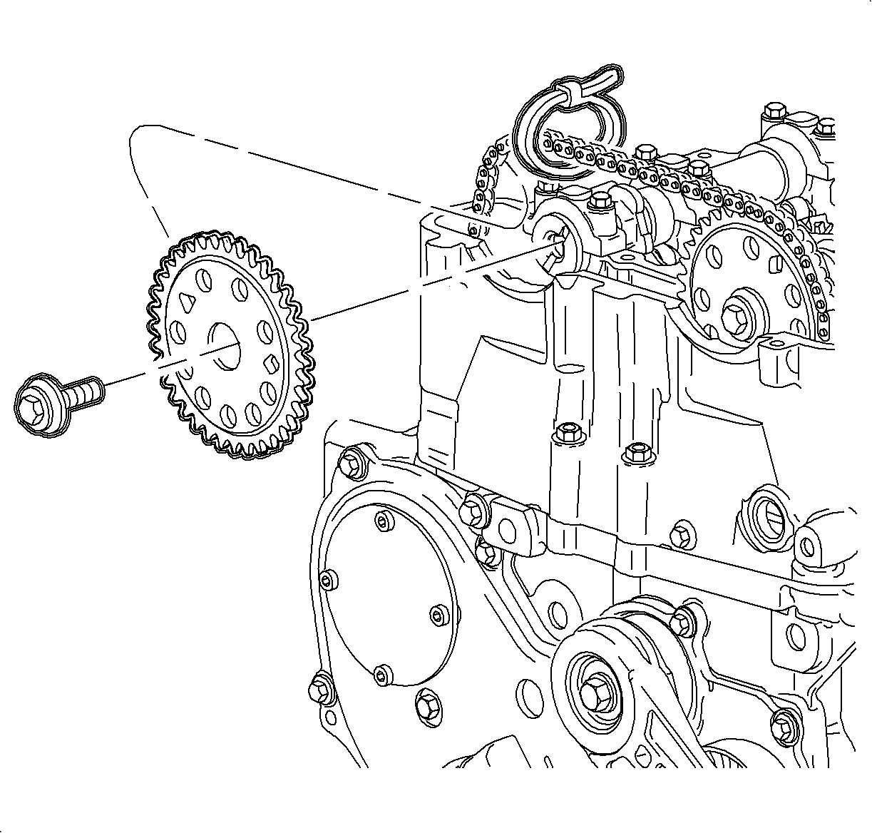
Important: Do not allow any load onto the timing chain upon loosening the camshaft sprocket bolts.
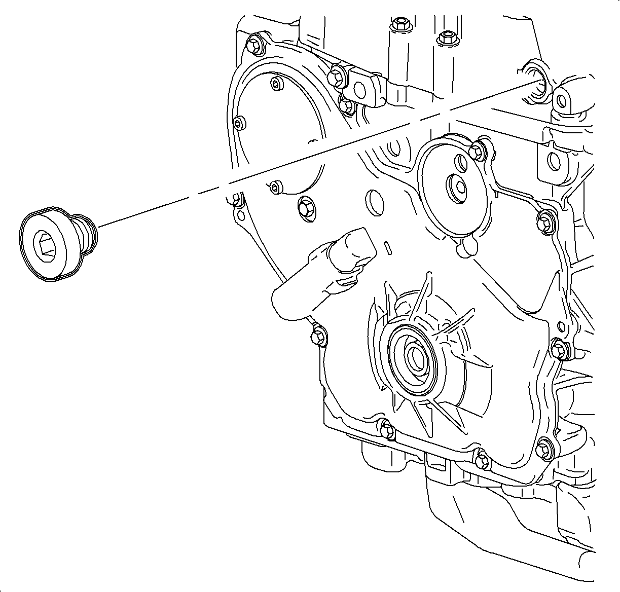
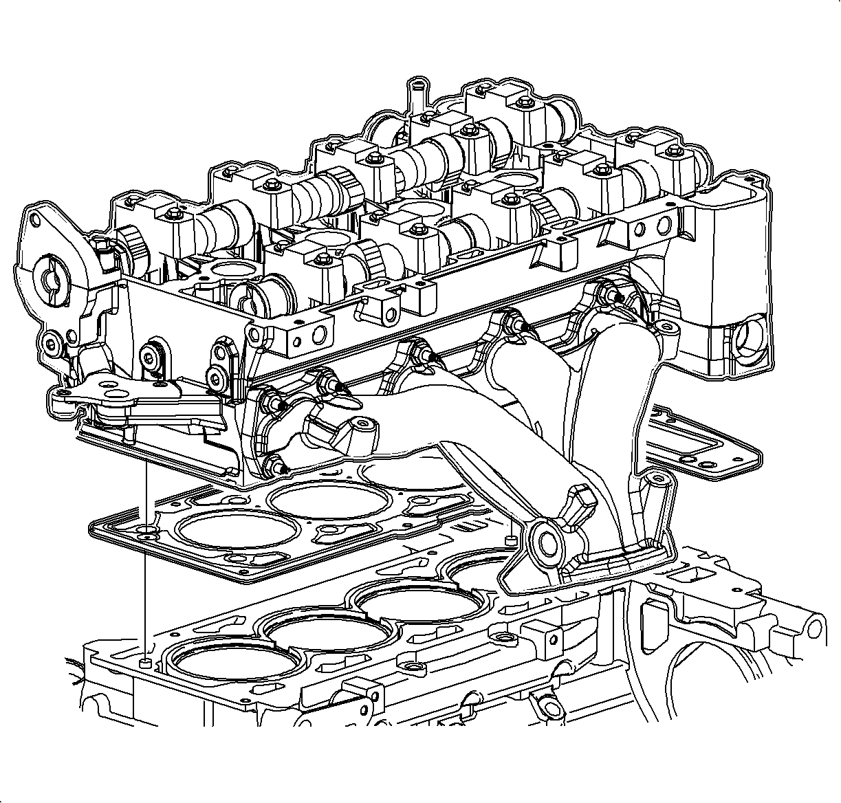
Notice: Be careful not to damage the aluminum the aluminum cylinder head and block gasket sealing surfaces when removing the cylinder head or during cleaning.
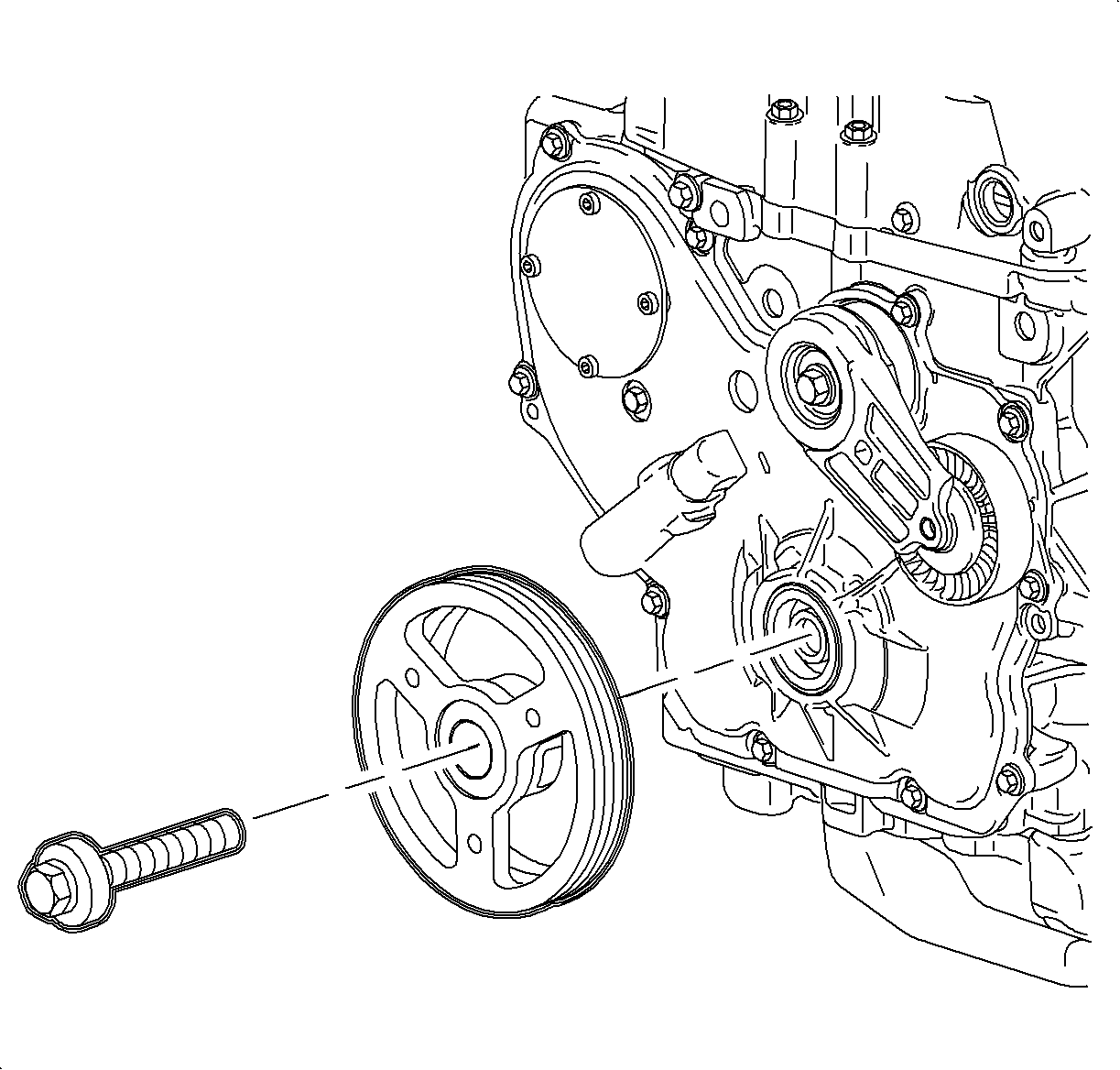
Important: The crankshaft damper pulley bolt head and washer assembly prevents oil leakage at the center of the pulley. Do not damage the sealing surfaces. If the pulley cannot be removed by hand, use a three jaw puller.
Important: Do not pry against the cover.


Installation Procedure
- Set the crankshaft to 60° before or after top dead center (TDC).
- Install the head gasket placing OBEN facing the top.
- Install the cylinder head, aligning it on the dowels.
- Lightly apply clean engine oil to the threads and to the bottom side of the flange of the head bolts and allow the oil to drain before installing.
- Install and tighten the cylinder head bolts in sequence.
- Coat the front cylinder head bolts with LOCTITE 242®.
- Install the front cylinder head bolts.
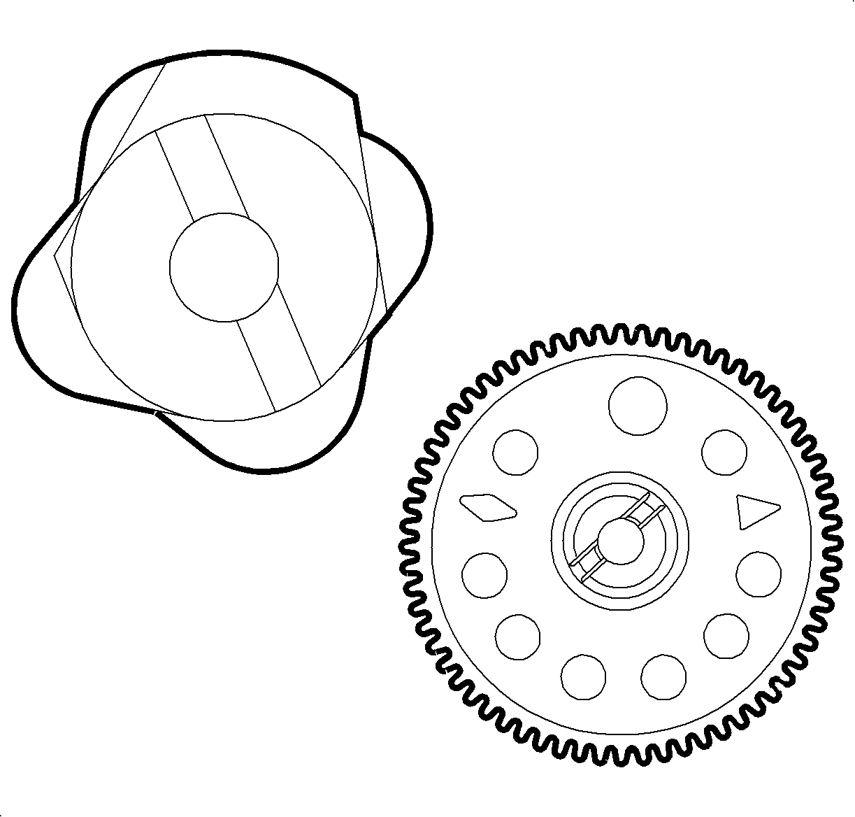
- Position the exhaust camshaft with the offset slot at the 2 o'clock position.
- Position the intake camshaft with the offset slot at the 11 o'clock position.
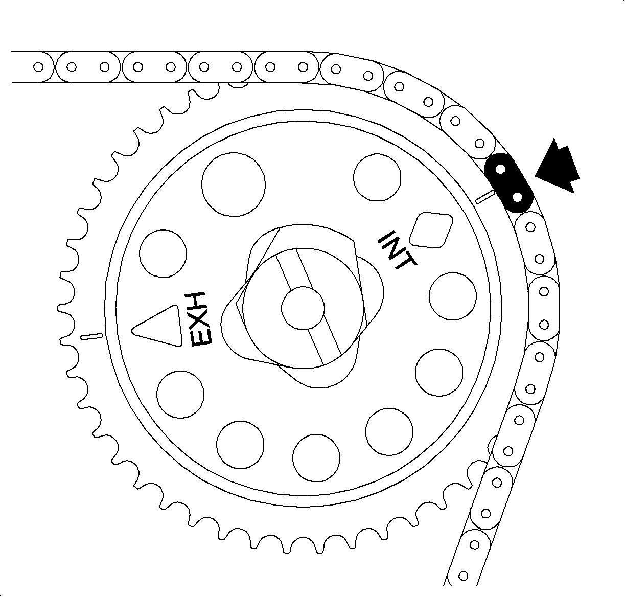
- Pull up the timing chain and install around the intake camshaft sprocket with the copper link lined up with the INT diamond timing mark.
- Install the sprocket onto the camshaft and align with the offset slot.
- Install the new camshaft sprocket bolt. Do not tighten.
- Route the chain around the crankshaft sprockets and align the silver link to the timing mark.
- Install the adjustable timing chain guide through the opening on the top of the cylinder head and install the chain guide bolt.
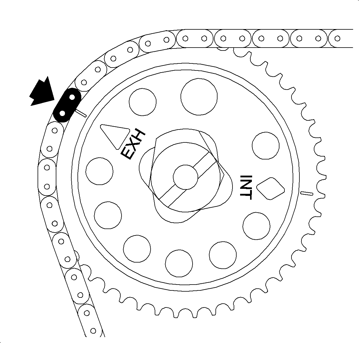
- Route the timing chain around the exhaust camshaft sprocket with the silver link lined up with the offset slot.
- Install the sprocket onto the camshaft and align with the offset slot.
- Install the new camshaft sprocket bolt. Do not tighten.
- Tighten the intake and exhaust camshaft sprocket bolts.
- Install the fixed guide and install the bolt.
- Apply LOCTITE PST565 to plug the threads.
- Install the fixed timing chain guide bolt access hole plug.
- Reset the timing chain tensioner by depressing the plunger.
- Install the sealing ring onto the tensioner and install.
- Gently tap the top of the chain, between the camshaft sprockets, with your hand. This will engage the tensioner onto the adjustable chain guide.
- Install the upper timing chain guide and bolts.
- Install the front cover gasket and the front cover.
- Install the front cover bolts.
- Install the water pump bolt.
- Install the drive belt tensioner and belt.
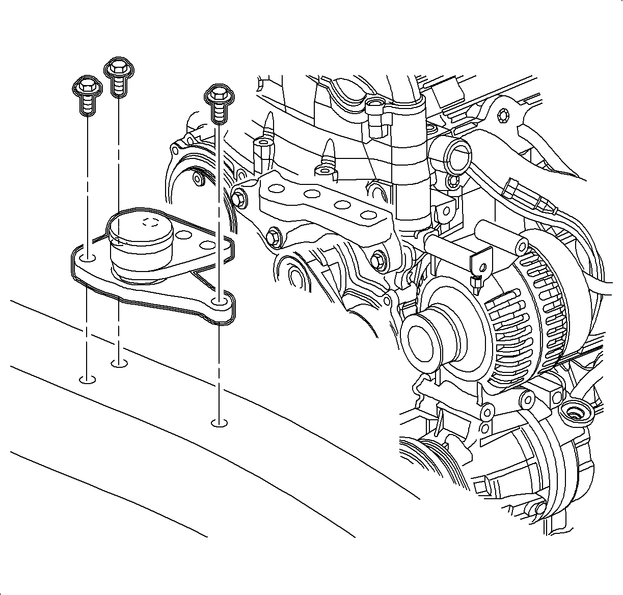
- Install the engine mount bracket onto the engine and install the bolts.
- Install the engine mount assembly-to-side rail and install the fasteners.
- Lower the engine and align the engine mount bolts.
- Install the engine mount bolts-to-bracket bolts.
- Remove the floor jack.
- Raise the vehicle.
- Install the crankshaft damper.
- Lubricate the front oil seal and the seal surface of the crankshaft balancer with an engine oil supplement.
- Install the damper onto the crankshaft indexing keyway. Use care to properly align the keyway and flats on the damper with the oil pump drive.
- Install the new crankshaft damper pulley bolt.
- Install the drive belt.
- Install the A/C line clamps.
- Install the right wheel splash shield.
- Install the tire/wheel.
- Install the wheel cover.
- Lower the vehicle.
- Install the camshaft cover. Ensure that the camshaft cover seals are properly seated in the cover.
- Install the cover bolts and ground strap nut.
- Install the power steering pump.
- Install the spark plugs.
- Install the ignition coil and module assembly to the camshaft cover.
- Install the intake manifold onto the intake manifold. The gasket may be reused if not damaged.
- Install the intake manifold.
- Install the intake manifold bolts and nuts. Tighten by starting from the center bolt and working outward.
- Attach the wiring harness to the brackets located under the intake manifold.
- Install the oil indicator tube assembly.
- Install the throttle body. The gasket may be reused if not damaged.
- Install the throttle body mounting bolts and nuts. Install the throttle cable.
- Position the engine harness and install the fasteners.
- Connect the electrical connections.
- Install the camshaft cover ground strap.
- Attach the cylinder head degas hose onto the coolant reservoir and attach to the harness retainers.
- Attach the hoses.
- Install the fuel lines. Ensure that the lines are routed correctly.
- Clip the lines into place and install the fuel line bracket and bolt.
- Install the exhaust flange onto the exhaust flange.
- Raise the vehicle.
- Position the manifold down pipe onto the flange studs.
- Install the flange nuts.
- Install the exhaust down pipe to the resonator bolts.
- Drain the oil.
- Lower the vehicle.
- Install the exhaust manifold heat shield and install the bolts.
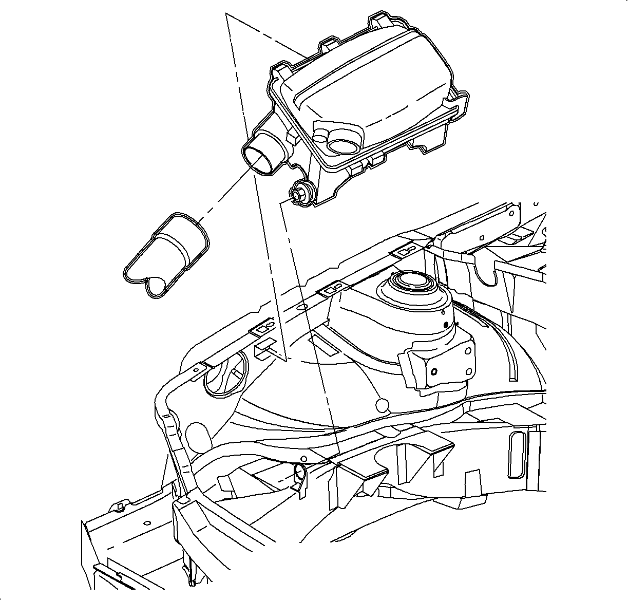
- Install the air cleaner and inlet tube assembly.
- Add engine oil.
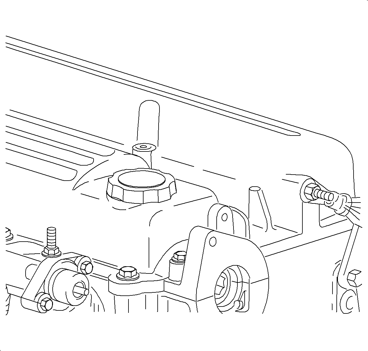
- Check the level and install the oil cap.
- Fill the coolant tank.
- Connect the battery cable.
- Start the vehicle and inspect for leaks.
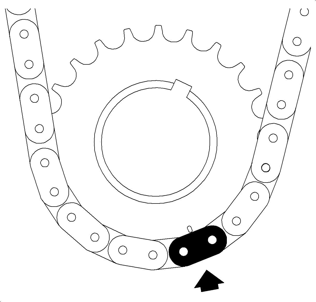
Important: Set crankshaft to 60 degrees before top-dead center or after TDC to prevent valve to piston contact.

Important: Always use new cylinder head bolts.
Tighten
Tighten the cylinder head bolts to 30 N·m
(22 lb ft) +155°.
Tighten
Tighten the cylinder head front chain case bolts
to 20 N·m (15 lb ft).
Notice: Refer to Torque to Yield Bolts Notice in the Preface section.

Important: There is a 2nd design adjustable guide with a contact pad for the 2nd design notched tensioner. A 2nd design guide should be used only with a 2nd design tensioner.

Tighten
Tighten the timing chain adjustable guide bolt to
10 N·m (89 lb in).
Notice: Refer to Torque to Yield Bolts Notice in the Preface section.
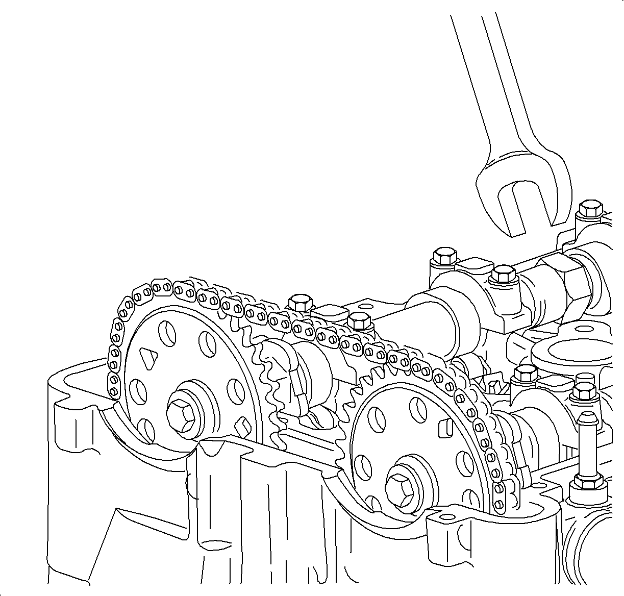
Notice: Use a 24 mm wrench to support the camshaft while applying torque to camshaft sprocket bolt. Do not torque camshaft bolts against timing chain, as it may damage the timing chain.
Important: Ensure that all the timing marks and colored links are aligned properly before proceeding to the next step.
Tighten
Tighten the camshaft sprocket bolts to 85 N·m
(63 lb ft) +30°.

Tighten
Tighten the timing chain fixed guide bolts to 10 N·m
(89 lb in).

Tighten
Tighten the timing chain guide bolt access hole
plug to 40 N·m (30 lb ft).

Important: There is a 2nd design tensioner with a notch at the plunger end of the tensioner. This tensioner should be used only with the 2nd design adjustable guide.
Tighten
Tighten the timing chain tensioner bolts to 75 N·m
(55 lb ft).

Tighten
Tighten the timing chain upper guide bolts to 10 N·m
(89 lb in).
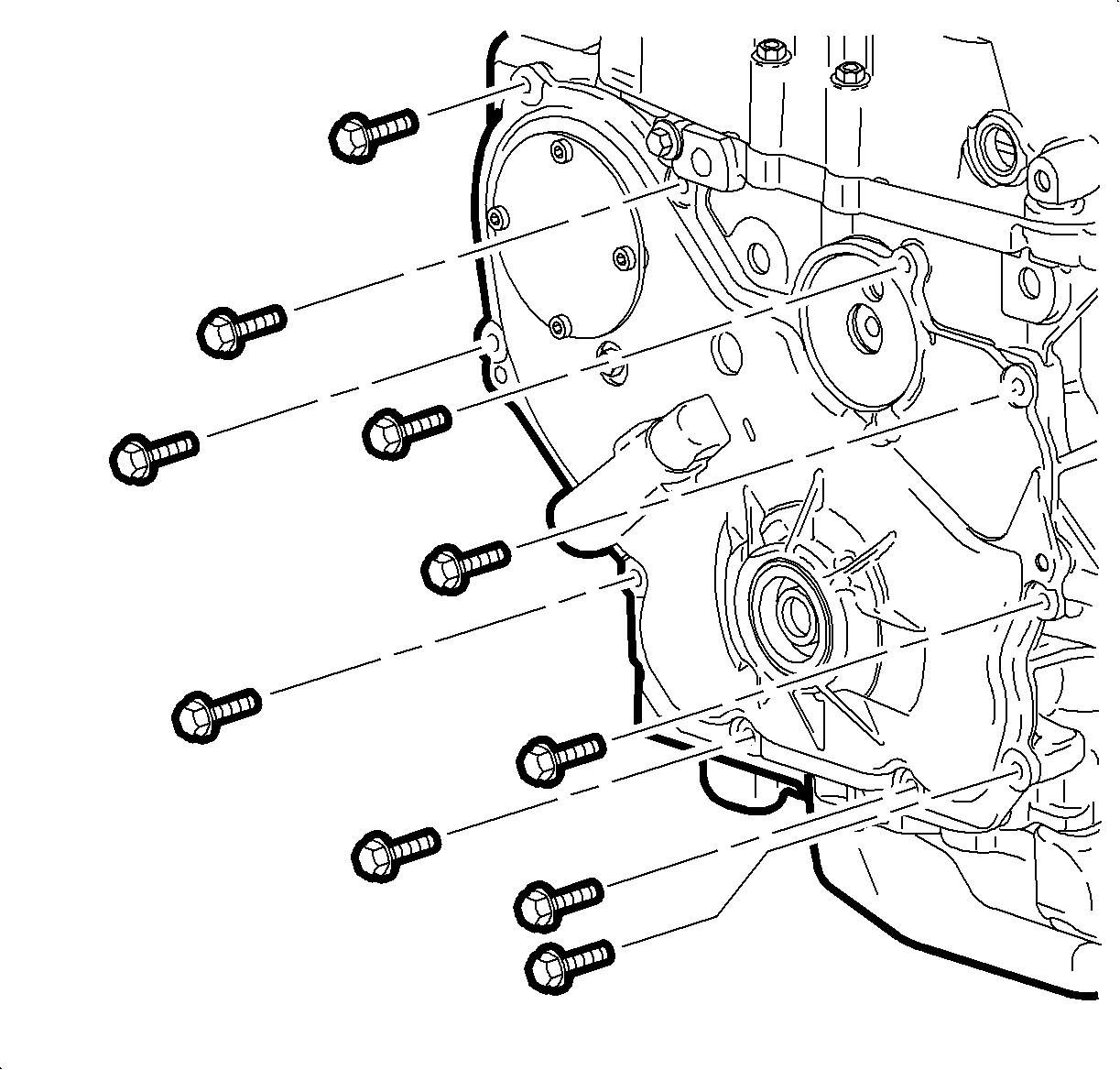
Important: Ensure that all of the timing marks and colored links are aligned properly before proceeding to the next step.
Tighten
Tighten the front cover-to-block bolts to 25 N·m
(18 lb ft).

Tighten
Tighten the water pump bolts to 25 N·m
(18 lb ft).

Tighten
Tighten the drive belt tensioner bolt to 45 N·m
(33 lb ft).

Tighten
Tighten the engine mount bracket-to-engine bolts
90 N·m (66 lb ft).

Tighten
Tighten the engine mount-to-body bolts to 55 N·m
(41 lb ft).

Tighten
Tighten the engine mount-to-engine mount bracket
bolts to 55 N·m (41 lb ft).

Notice: Misalignment of the keyway may cause damage to the oil pump.

Important: It may be necessary to lower the engine slightly with a crow bar so that the bolt-head clears the frame rail.
Tighten
Tighten the crankshaft damper pulley bolt to 100 N·m
(74 lb ft) +75°.


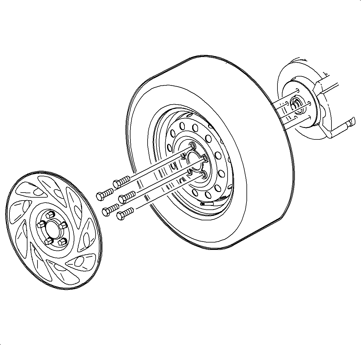
| 43.1. | Hand tighten all 5 wheel bolts. |
| 43.2. | Use a torque wrench to initial tighten wheel bolts using a crisscross pattern. |
Tighten
Tighten the wheel bolts (initial torque) to 63 N·m
(46 lb ft).
| 43.3. | Use a torque wrench to final tighten wheel bolts using a crisscross pattern. |
Tighten
Tighten the wheel bolts (final torque) to 125 N·m
(92 lb ft).

Tighten
Tighten the camshaft cover bolts to 10 N·m
(89 lb in).
Tighten
Tighten the power steering pump bolts to 25 N·m
(18 lb ft).
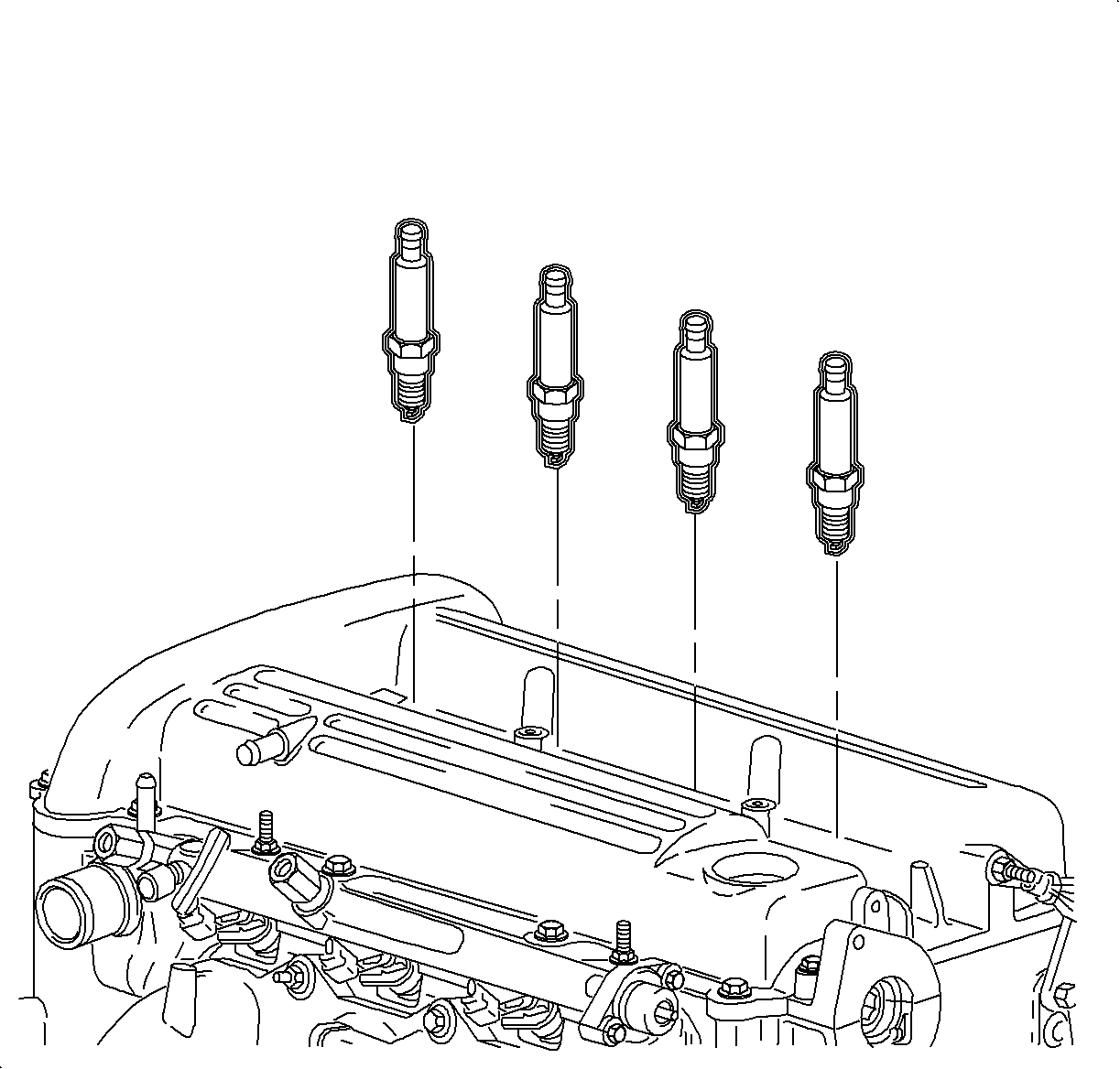
Tighten
Tighten the spark plugs to 20 N·m (15 lb ft).

Tighten
Tighten the ignition coil-to-camshaft cover bolts
to 8 N·m (71 lb in).

Tighten
| • | Tighten the intake manifold-to-cylinder head bolts to 10 N·m (89 lb in). |
| • | Tighten the manifold-to-cylinder head nuts to 10 N·m (89 lb in). |
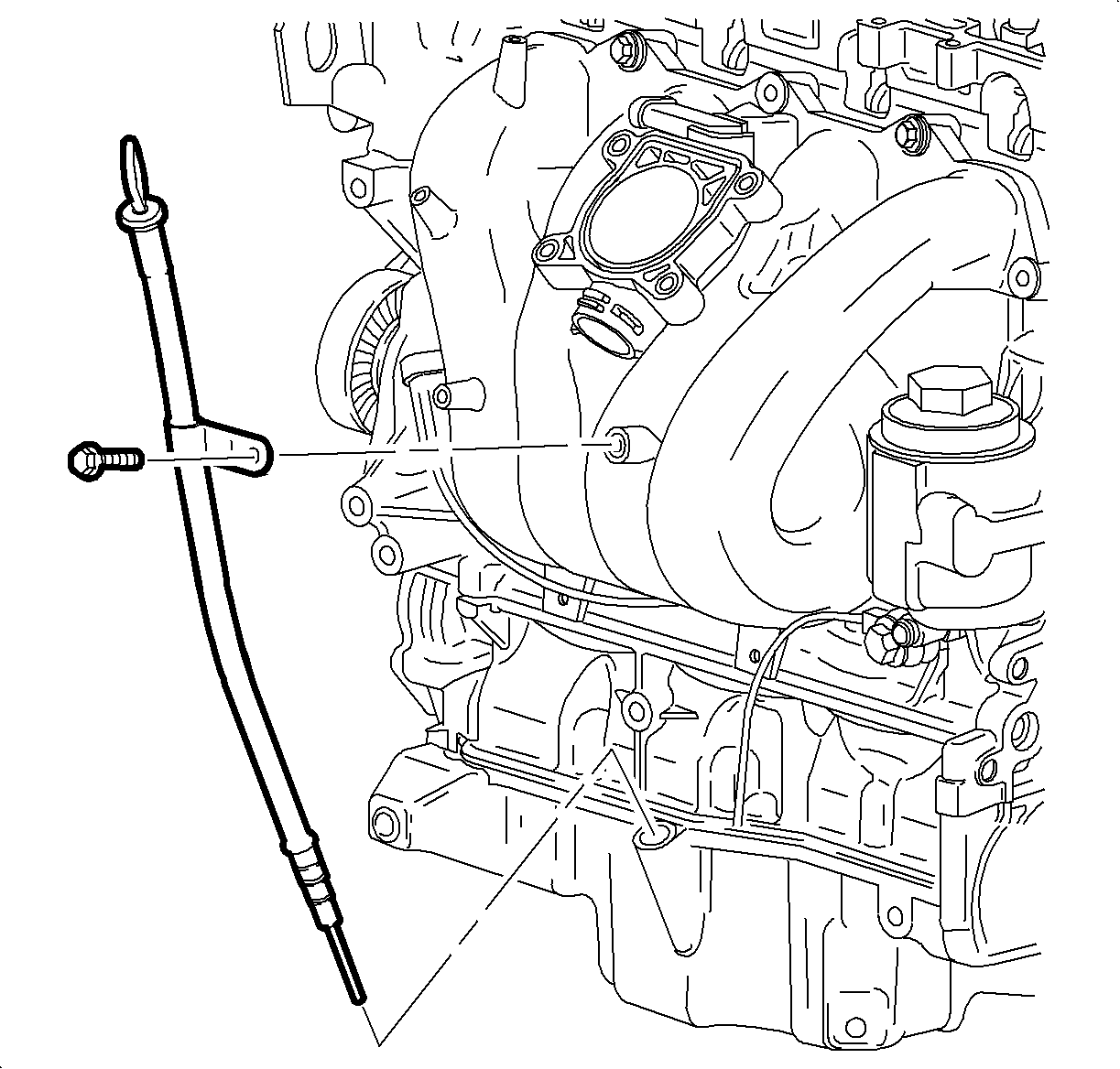
Tighten
Tighten the oil level indicator tube-to-intake manifold
bolt to 10 N·m (89 lb in).
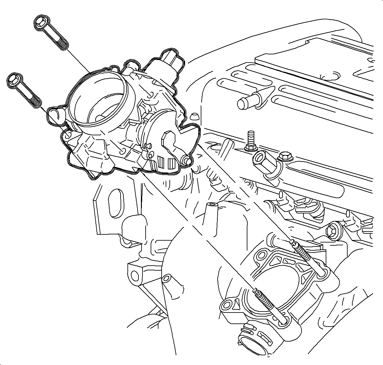
Tighten
| • | Tighten the throttle body bolts to 10 N·m (89 lb in). |
| • | Tighten the throttle body nuts to 10 N·m (89 lb in). |
Tighten
Tighten the engine harness bracket bolts to 10 N·m
(89 lb in).
Tighten
Tighten the camshaft cover ground strap fastener
to 10 N·m (89 lb in).
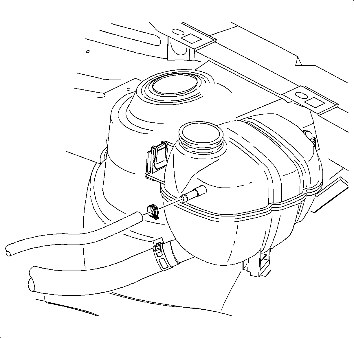
Tighten
Tighten the dogas hose bracket bolts to 10 N·m
(89 lb in).
| 62.1. | Upper radiator hose |
| 62.2. | Crankcase ventilation hose |
| 62.3. | Fuel pressure regulator hose |
| 62.4. | Brake booster hose |
| 62.5. | EVAP purge hose |
Notice: Replace plastic fuel retainer whenever the fuel supply is disconnected at the fuel rail. Install the new retainer into the female cavity of the connection. Care must be taken to assure that the locking tab is centered in the window of the female cavity. Firmly press the female connection onto the male end until a click is heard, then pull back to confirm engagement. Pinched, kinked, or damaged fuel lines must be replaced.
Tighten
Tighten the fuel line bolt to 10 N·m
(89 lb in).

Tighten
Tighten the exhaust manifold pipe-to-exhaust manifold
nuts to 30 N·m (22 lb ft).
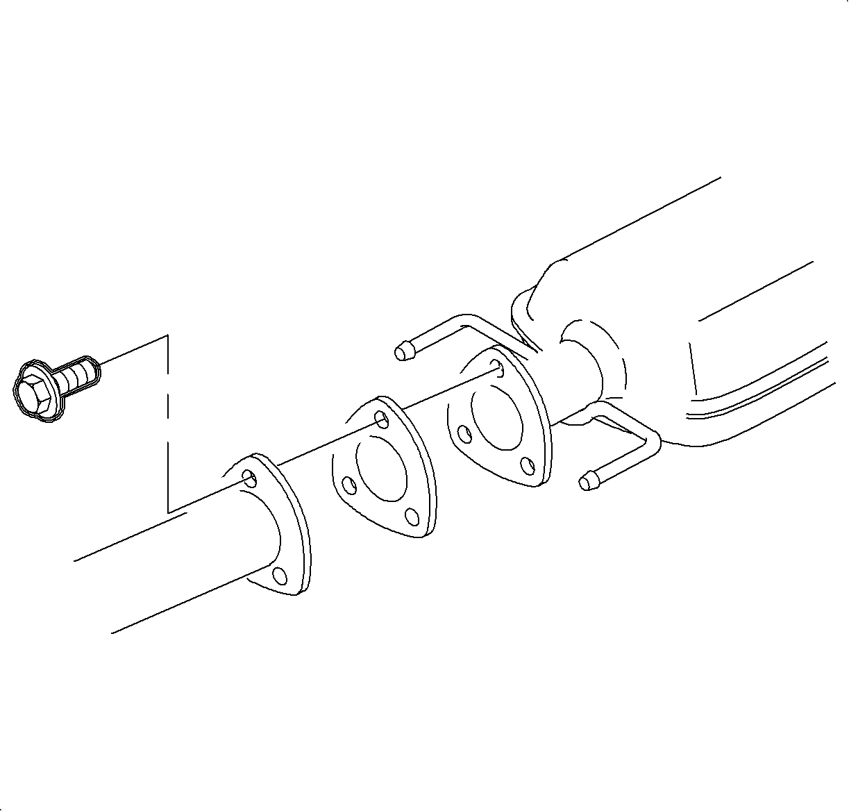
Tighten
Tighten the exhaust manifold pipe-to-resonator bolts
to 20 N·m (15 lb ft).
Tighten
Tighten the oil drain plug to 25 N·m
(18 lb ft).
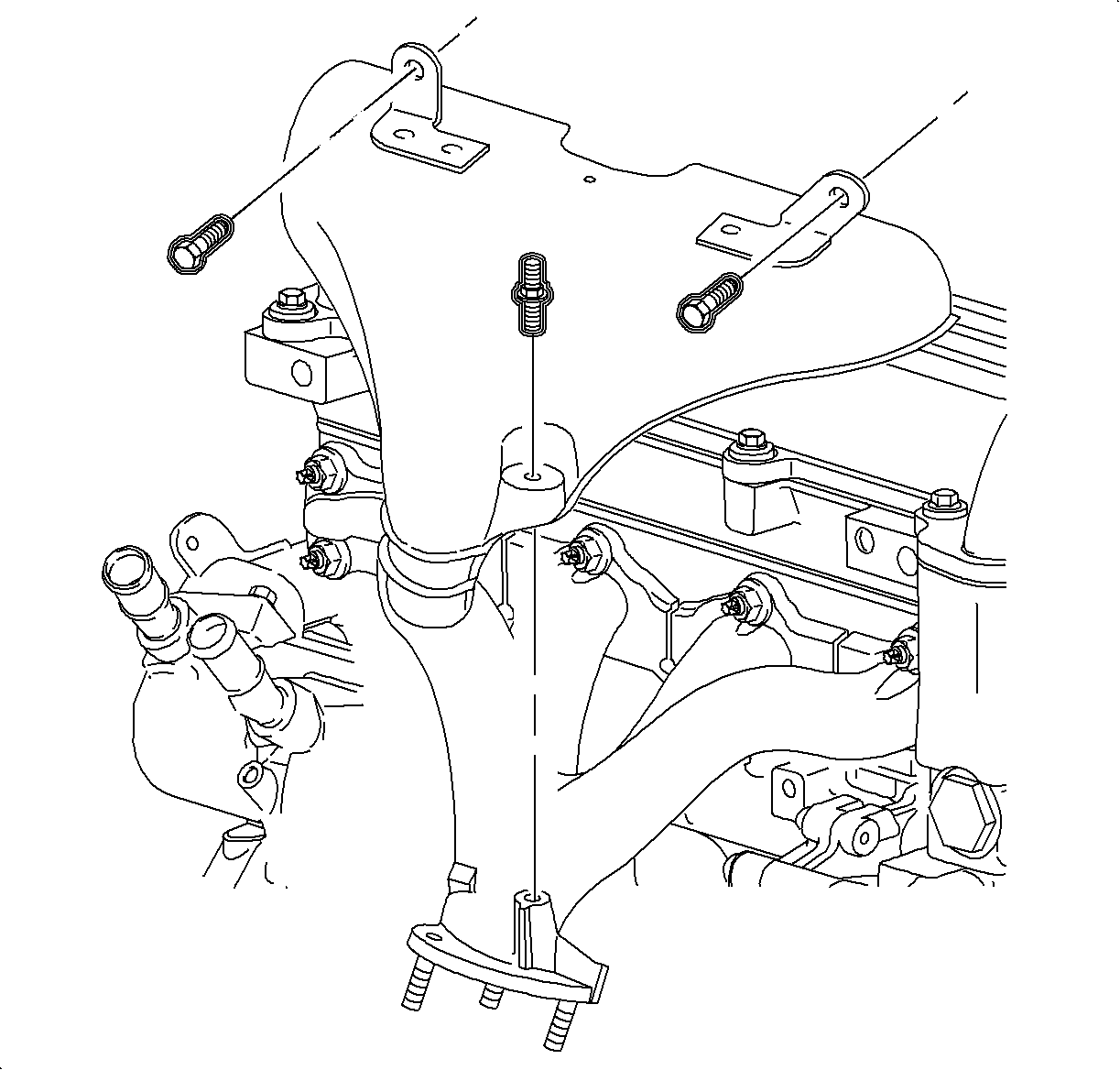
Tighten
Tighten the exhaust manifold heat shield bolts to
25 N·m (18 lb ft).
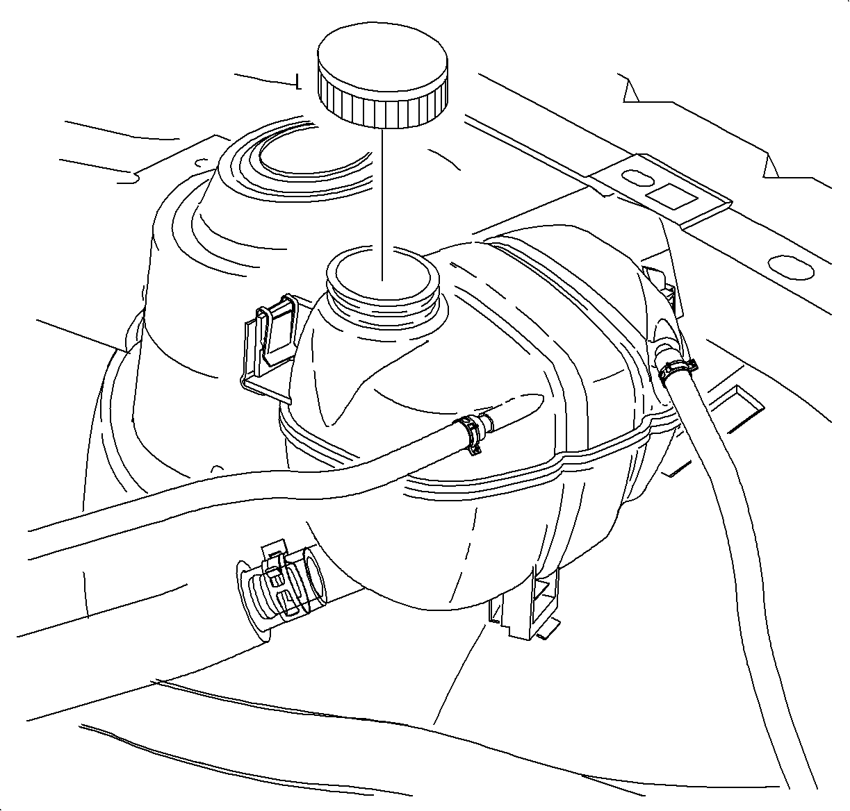
| 76.1. | Add 50/50 DEX-COOL® and water. |
Specifications
| • | The auto trans volume equals 6.9 quarts. |
| • | The manual trans volume equals 7 quarts. |
| 76.2. | Install the coolant surge cap. |
Notice: After cylinder block, head, or lifter replacement, it will be necessary to allow the engine to idle for 3-5 minutes. If the lifters are noisy, warm the engine up at less than 200 RPM. After the coolant temperature has reached approximately 85°C (185°F), cycle the engine RPM from idle to 300 RPM for approximately 10 minutes or drive the vehicle 8 kilometers (5 miles) to purge the air. If the air cannot be purged, the faulty lifters will have to be replaced.
