Removal Procedure
- Raise the vehicle on a hoist.
- Remove the front wheel and the tire assemblies. Refer to Tire and Wheel Removal and Installation in Tires and Wheels.
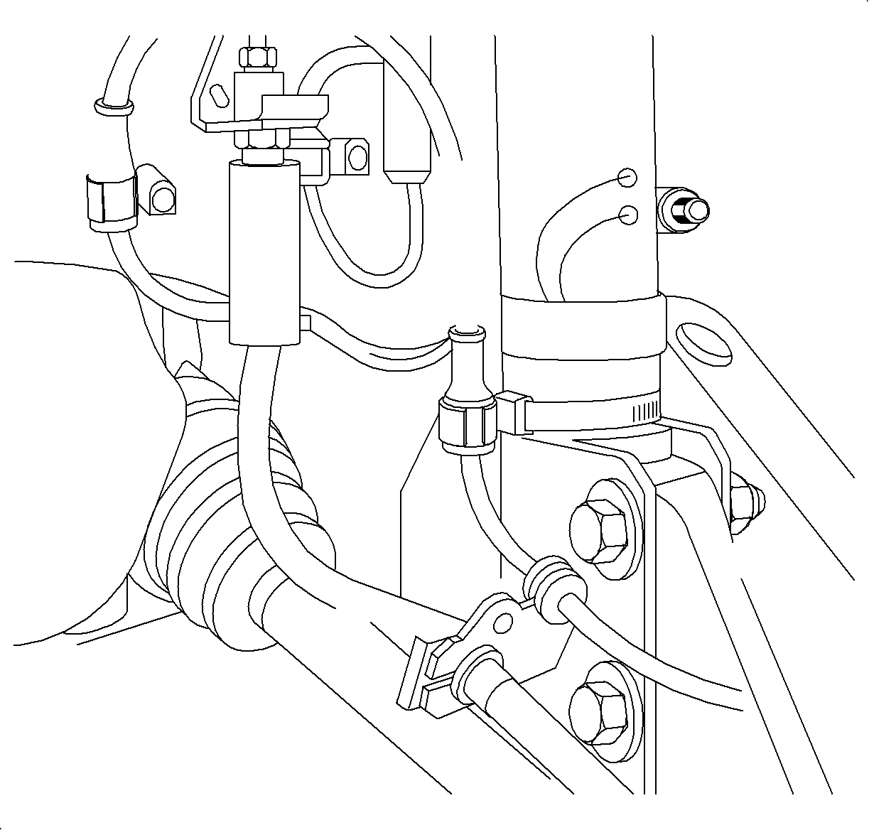
- Pry off the locking plate and remove the brake pressure hose from the strut.
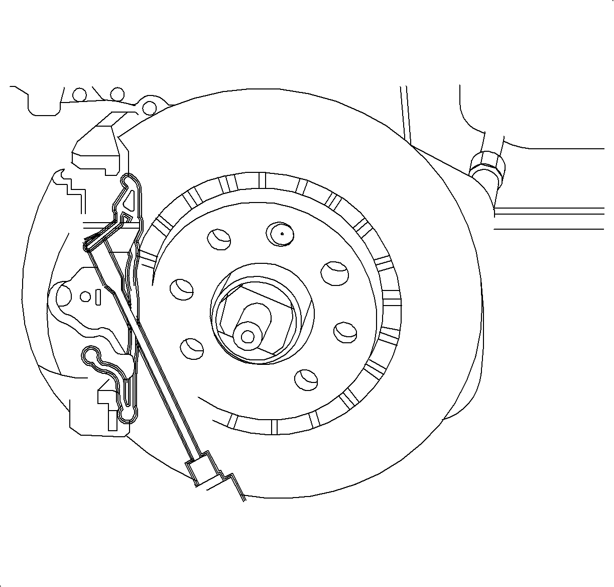
- Remove the caliper retainer spring.
- Remove the caliper-to-bracket guide pins.
- Remove the caliper assembly.
- Remove the inboard and the outboard brake pads from the caliper assembly.
- Inspect the guide pin boots and covers for damage. If damaged, replace.
- Inspect the piston boot for deterioration. If damage, overhaul the caliper.
- Inspect the guide pin for damage or corrosion. Replace if damaged or corroded.
- Repeat steps 3 through 8 for the opposite side of the vehicle.
Caution: Refer to Vehicle Lifting Caution in the Preface section.


Notice: Do not let weight of caliper hang on brake hose as this could damage the brake hose. Use mechanics wire to tie caliper to strut.
Important: Do not attempt to clean away the corrosion.
Installation Procedure
- Using a C-clamp, bottom the piston all the way into the caliper bore.
- Install the inner and the outer brake pads into the calipers.
- Position the caliper onto the caliper support bracket.
- Lubricate the straight section (not the threads) of the guide pins with silicone grease.
- Install the guide pins through the caliper body into the caliper support and tighten.
- Install the guide pin bushing caps.
- Install the caliper retention spring.
- Re-attach the brake hose to the strut assembly and install the lock plate.
- Repeat steps 1 through 7 for the opposite side of the vehicle.
- Position the wheel onto the hub.
- Install the wheel and tire assembly. Refer to Tire and Wheel Removal and Installation in Tires and Wheels.
- Lower the vehicle from the hoist.
- Prior to operating the vehicle, depress the brake pedal a few times until the brake pads are seated against the rotor.
Important: Never replace brake pads on one side of the axle only. The left and right side brake pads must be replaced only as axle sets.
Important: The piston boot must lie flat, below the level of the piston face.
Important: Linings are identified for left or right use. Install the linings so the arrow is pointing downward, with the forward rotation of the wheel.
Important: Remove all rust and corrosion from the caliper brackets when installing the brake pads. If installing used brake pads, remove all rust and corrosion from the ends of the brake pads and from the notch. Make sure the brake pads move freely in the caliper bracket when the brakes are assembled.
Notice: Be careful not to damage guide pin boot.
Notice: Refer to Fastener Notice in the Preface section.
Tighten
Tighten the caliper-to-bracket guide pins to 30 N·m
(22 lb ft).


Caution: Refer to Wheel Installation Caution in the Preface section.
Caution: Refer to Failure to Depress Brake Caution in the Preface section.
