Tools Required
87 92 335 Shift Linkage Lock Pin
Removal Procedure
- Disable the SIR system. Refer to "Disabling the SIR system" in this service manual.
- Remove the console. Refer to "Console Removal" in this service manual.
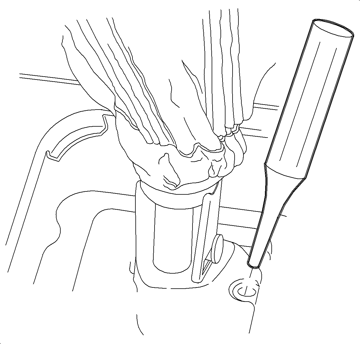
- Move the shift lever to 5th/Reverse gate and use a 3/8 in. punch to hold in place.
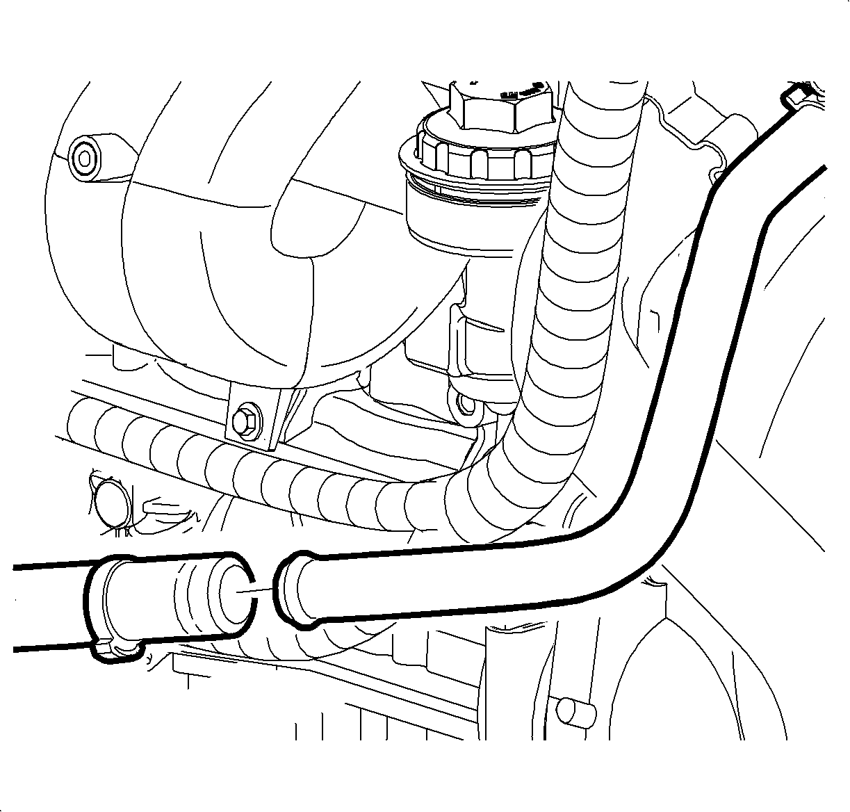
- Remove the clamp from the AIR hose behind the cooling fan.
- Separate the AIR tube from the hose and push the tube back towards the transaxle.
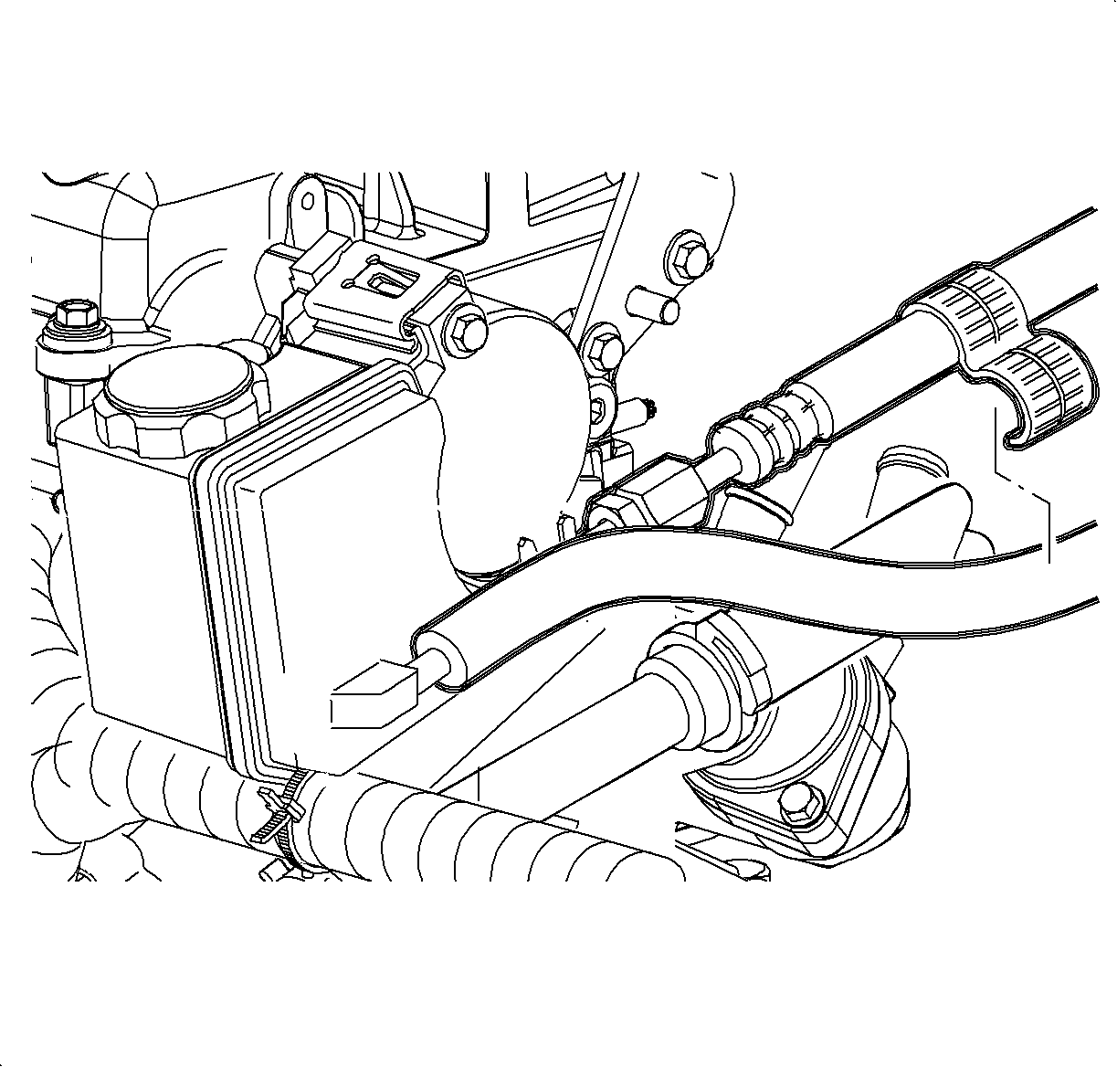
- Remove the hose clip holding the 2 power steering lines together.
- Lock the transaxle shift control shaft in 5th/Reverse gate. There is a hole on top of the transaxle that will have either a spring loaded locking pin or a hole plug.
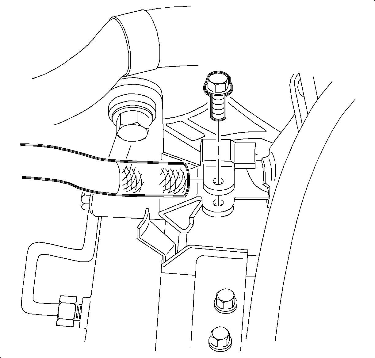
- Loosen the pinch bolt securing the control assembly rod to the control shaft lever assembly.
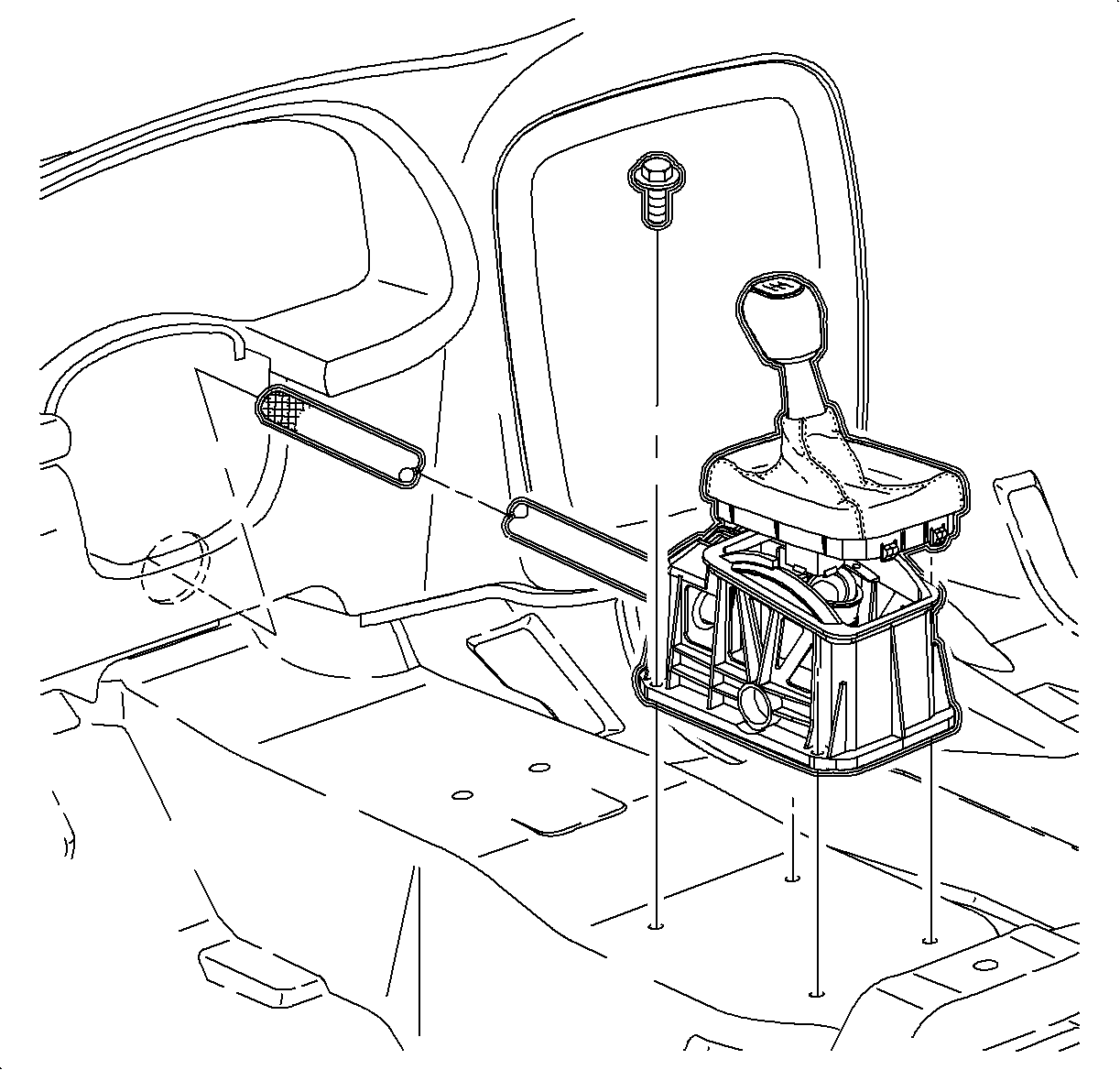
- Remove the control assembly-to-floor pan bolts and pull the assembly rearward to remove.
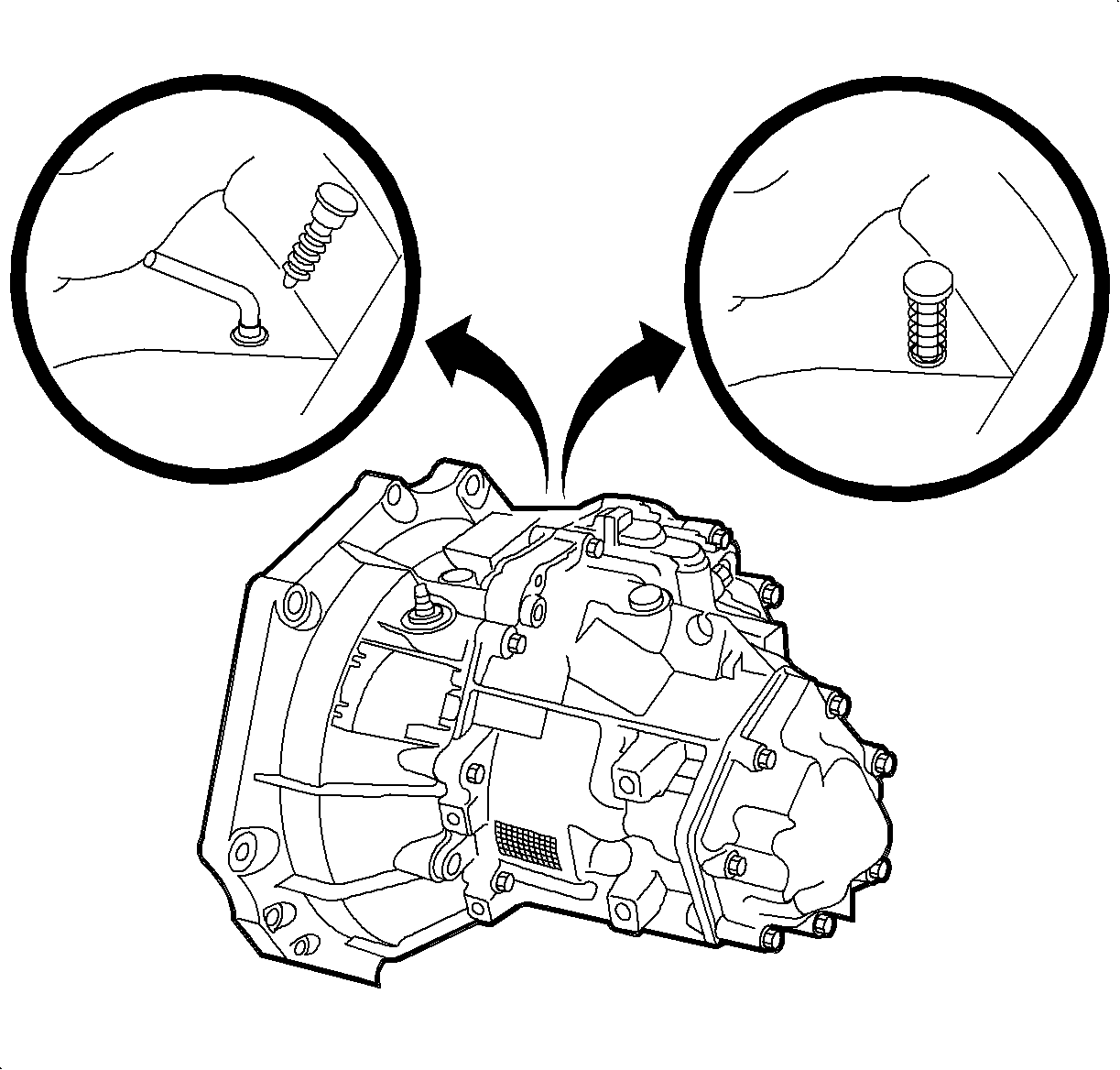
| • | If the hole has a spring loaded locking pin, depress the pin to lock transaxle shift control shaft in 5th/Reverse gate. |
| • | If the hole has a plug in it, remove the plug and insert the 87 92 335 in the hole to lock the transaxle shift control shaft in 5th/Reverse gate. If the plug is not damaged, it can be reused. |
Installation Procedure
- Install the control assembly into the vehicle and install the control assembly-to-floor pan bolts.
- Move the shift lever to the 5th/Reverse gate and use a 3/8 in. punch to hold in place.
- Tighten the pinch bolt securing the control assembly rod to control shaft lever assembly.
- Release the transaxle shift control shaft.
- Install the hose clip to the 2 power steering lines.
- Pull the AIR tube back to the original position.
- Insert the tube into the hose and install the clamp.
- Ensure the stand-off clip between the AIR tube and the wiring harness is installed correctly.
- Install the console. Refer to "Console Installation" procedure in this service manual.
- Enable the SIR system. Refer to "Enabling the SIR System" procedure in this service manual.
Notice: Refer to Fastener Notice in the Preface section.

Important: When installing the control assembly, make sure the control assembly rod does not damage the pass-through grommet. Make sure the control assembly rod is correctly located in the guide control assembly before securing the control assembly to the floor pan.
Tighten
Tighten the control assembly-to-floor pan bolts
to 8 N·m (71 lb in).

Tighten
Tighten the control assembly rod-to-control lever
assembly pinch bolt to 12 N·m (9 lb ft) + 180°.

| • | If the transaxle has a spring loaded locking pin, remove the punch from the shift lever and rock the lever back and forth until the lever can be moved freely. |
| Important: If the transaxle hole plug was damaged during removal, install a new plug during assembly. |
| • | If there was a plug in the transaxle hole, remove the punch from the shift lever, remove the 87 92 335 , and install the plug. |


Important: The clamp must be installed with the locking portion facing down.
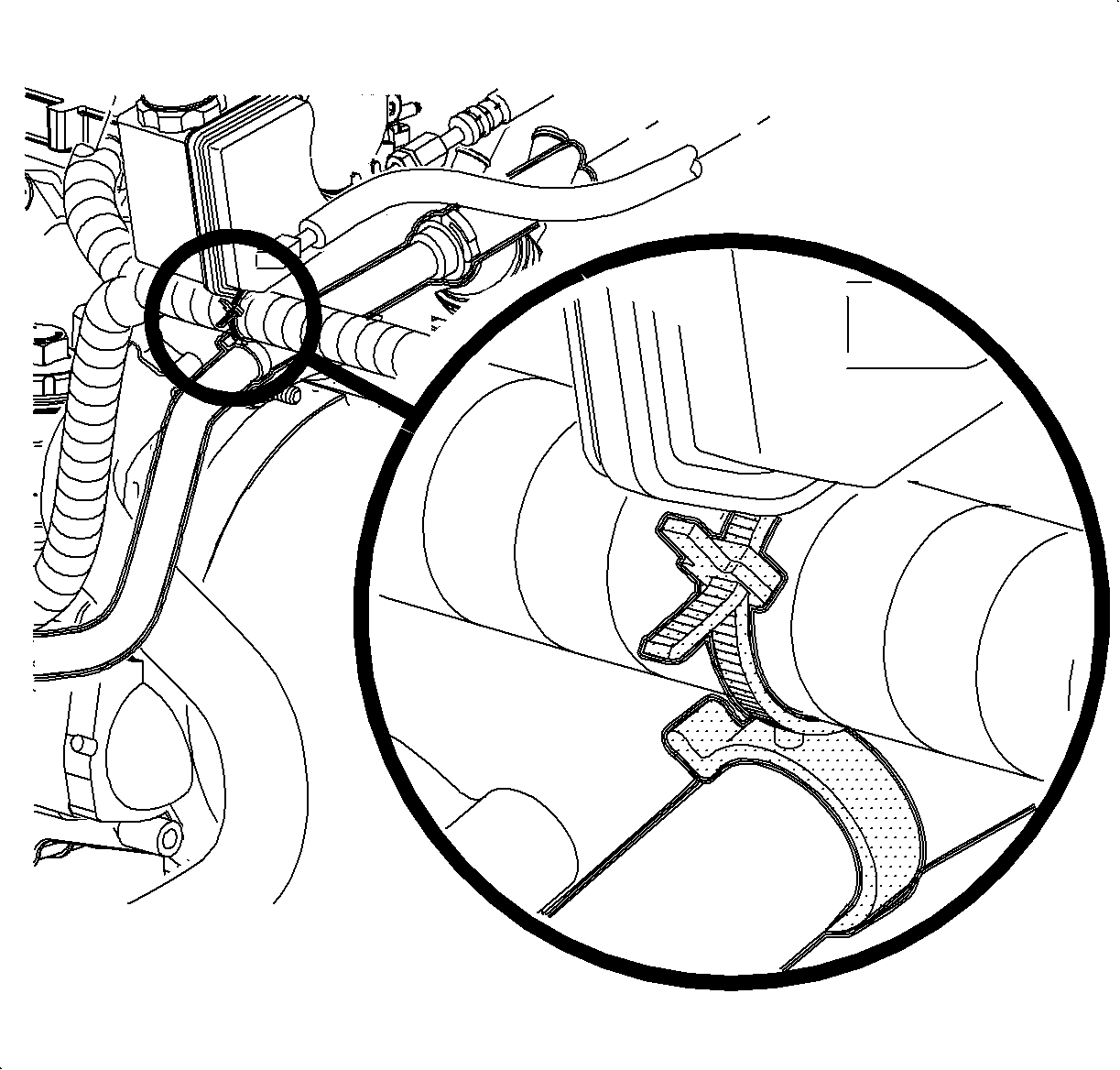
Notice: There is a stand-off clip between the AIR tube and the wiring harness at the front of the transaxle. This must be in place to eliminate the possibility of chafing between the tube and the harness.
