Tools Required
J 25031-A Three Jaw Puler
Removal Procedure
- Place the transaxle in 3rd gear.
- Raise the vehicle. Drain the transaxle lubricant by removing the transaxle drain plug (1).
- Remove the rear cover. Refer to Rear Cover Removal.
- Using a punch and hammer, tap out the 5th gear fork retaining pin and discard.
- Remove the 5th gear fork and synchronizer sleeve together.
- Remove the 5th gear synchronizer hub snap ring and discard. This is easier if the hub is tapped down first.
- Use the J 25031-A to remove the 5th gear synchronizer hub.
- Remove the blocking ring, blocking ring spring, 5th gear, and 5th gear bearing assembly.
- If the 5th synchronizer sleeve removed from the transaxle looks like the sleeve on the left, then it is a 1st design. The identification mark for the 2nd design is the extra groove on the top of the 5th gear sleeve.
- If the 5th gear blocking ring removed from the transaxle does not have a part number embossed on the bottom of the blocking ring, then it is a 1st design.
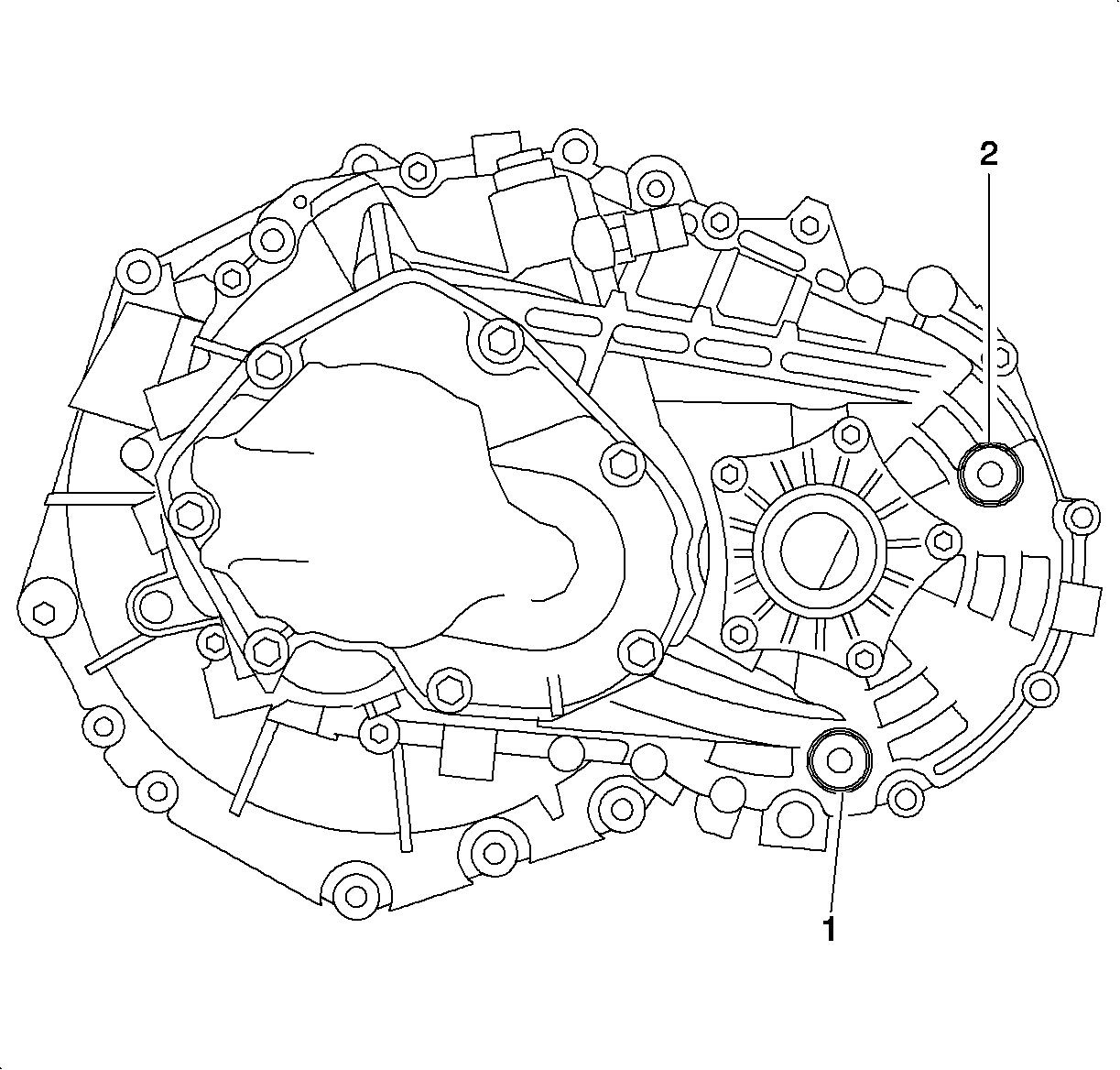
Caution: Refer to Vehicle Lifting Caution in the Preface section.
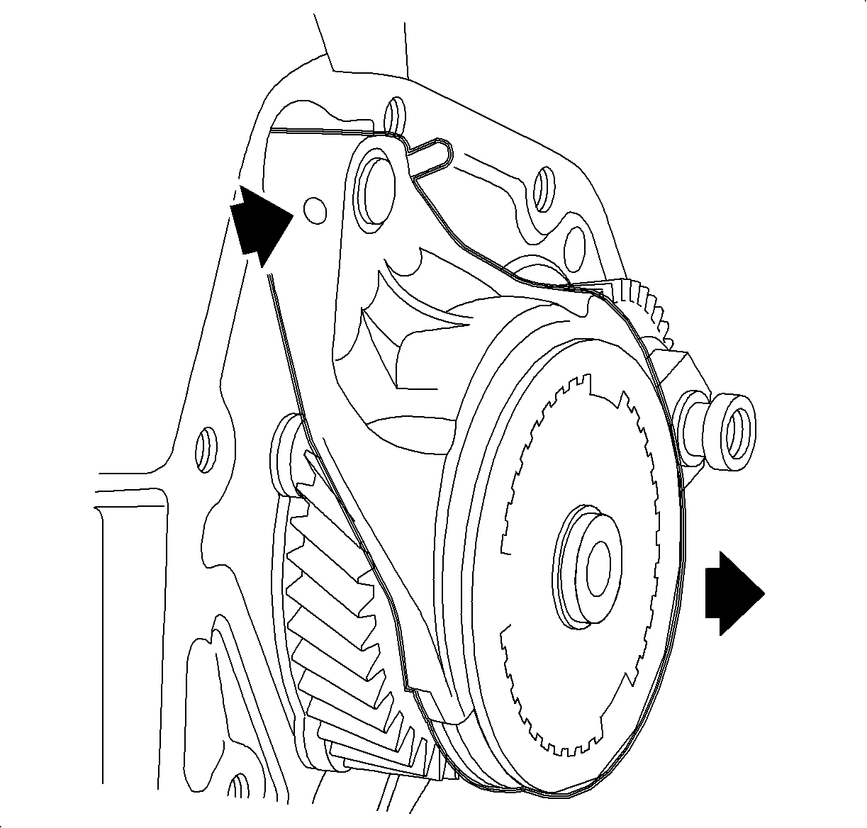
Important: Before removing the 5th gear shift fork and synchronizer sleeve, mark the position of the sleeve relative to the synchronizer hub to assist in reassembly.
Important: Make sure the 5th gear shift shaft does not come out of the transaxle when the 5th gear shift fork is removed.
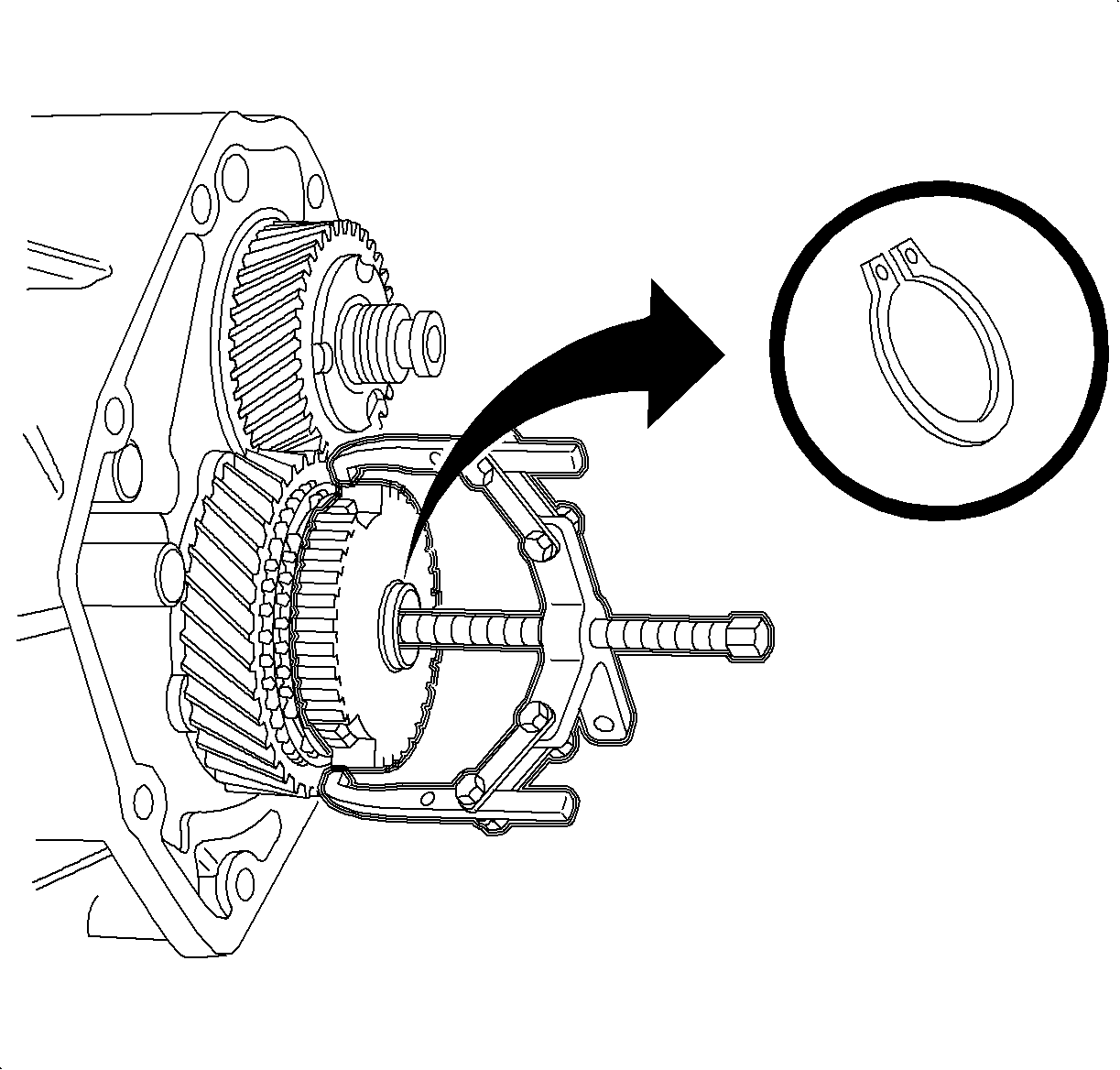
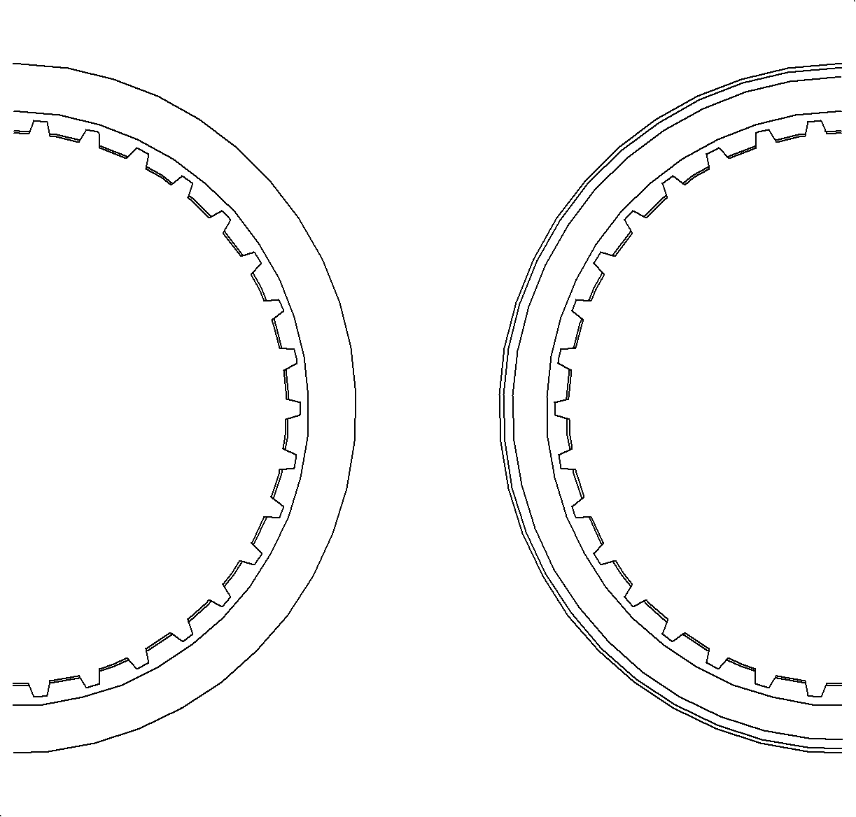
Important: When a manual transaxle with a serial number before T02075 is repaired for a 5th gear synchronizer failure, it must be determined whether the synchronizer components are of the 1st design or the 2nd design.
The illustrations show the first design, the left hand of the illustration, and the second design, the right half of the illustration, of the 5th gear synchronizer components.Important: All transaxles built prior to the T02075 serial number will be of the first design unless they have been previously repaired for this condition. All service parts are of the second design.
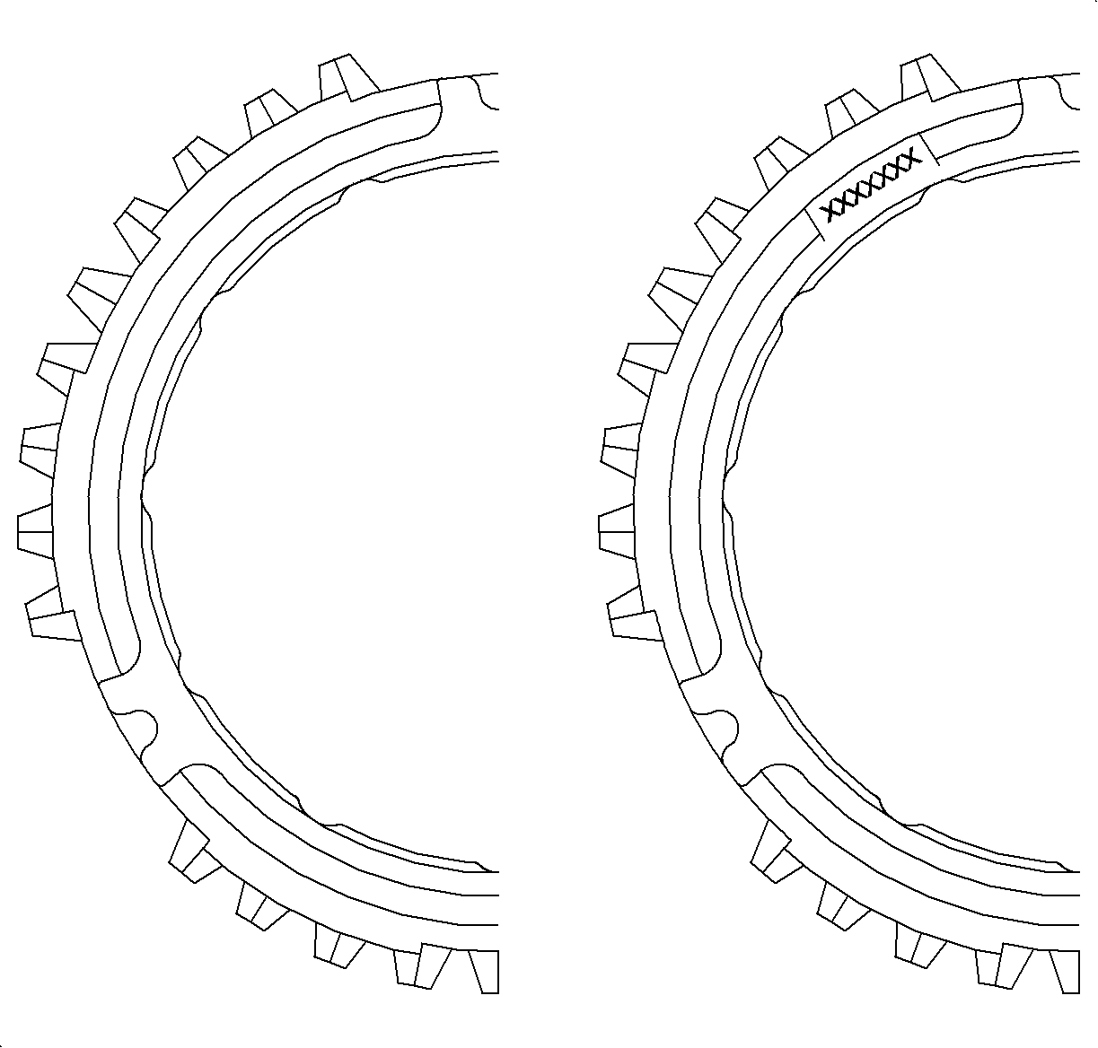
Important: If either the 5th synchronized sleeve or blocking ring is a 1st design and needs to be replaced, then both the sleeve and the blocking ring must be replaced with the 2nd design parts as a unit. If the blocking rings and sleeve have already been replaced with the 2nd design components, then only replace the parts as needed.
Installation Procedure
- Install the 5th drive gear bearing assembly and the 5th drive gear.
- Install the blocking ring and blocking ring spring on the 5th gear.
- Carefully tap the synchronizer hub onto the input shaft using a mallet and large socket.
- Install a new 5th gear synchronizer hub snap ring.
- Install the 5th gear fork and synchronizer sleeve together. Reference the sleeve alignment mark made during disassembly.
- Install a new 5th gear fork retaining pin.
- Install the rear cover. Refer to Rear Cover Installation.
- Clean and apply thread sealant P/N 21485278 to the transaxle drain plug (1) and install.
- Remove the transaxle level plug (2) and, using a funnel with a flexible spout or a quart bottle hand pump, add manual transaxle lubricant P/N 21018899 until the fluid begins to flow out of the level plug opening.
- Clean and apply thread sealant P/N 21485278 to the transaxle level plug (2) and install.
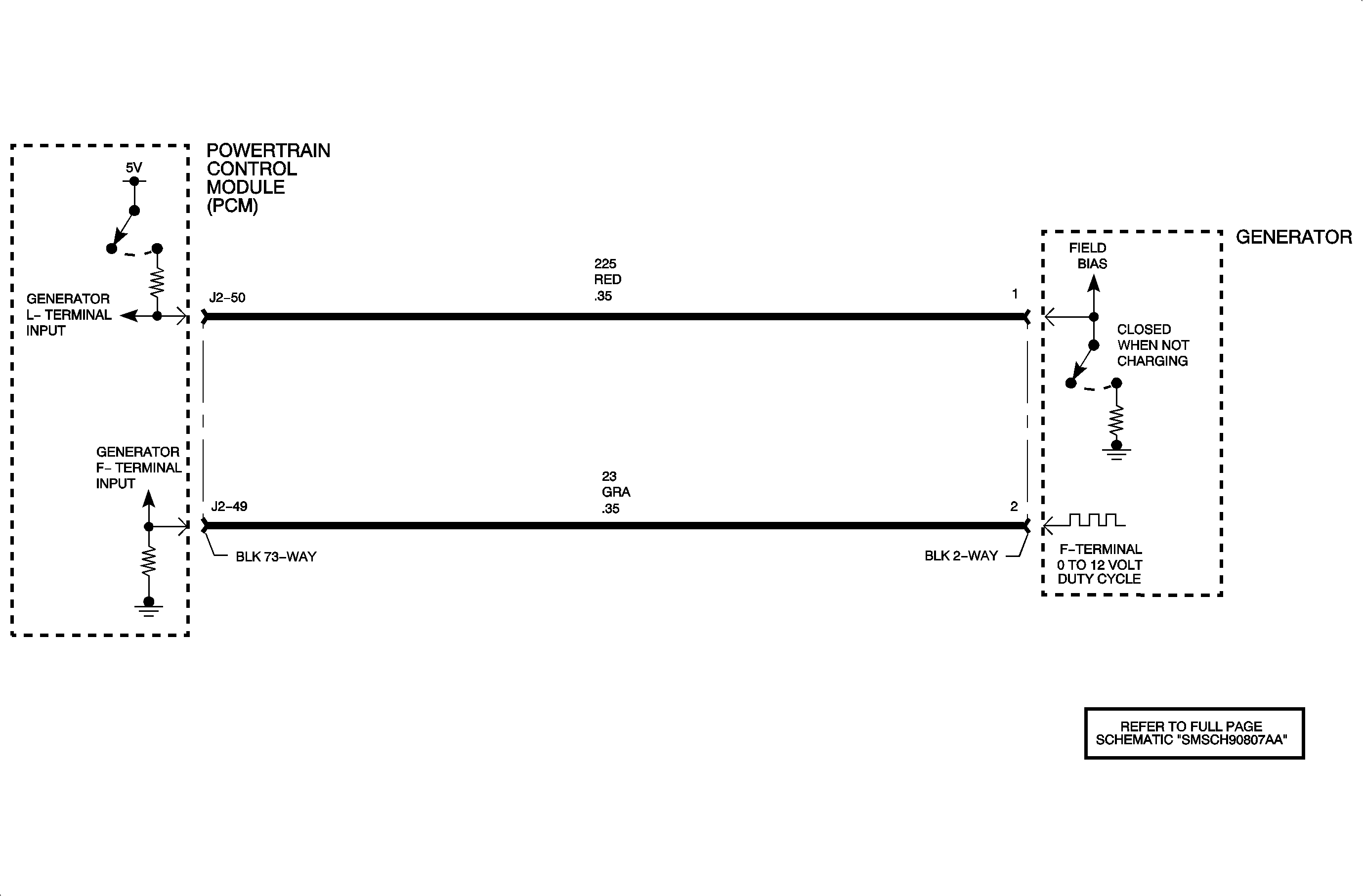
Important: Lubricate the bearing assembly with manual transaxle lubricant P/N 21018899 during assembly.
Important: Gaps in the synchronizer hub must align with the blocking ring lugs.
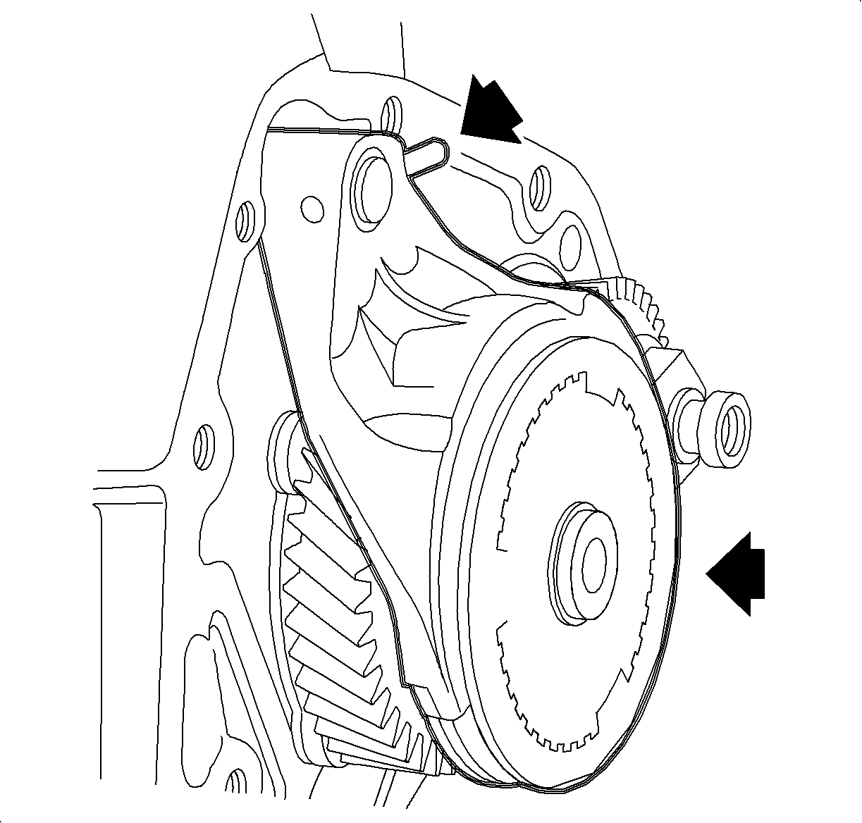
Important: The 5th gear synchronizer sleeve can only be placed on the hub when tall teeth on the sleeve are aligned with deep teeth on the hub.

Tighten
Tighten the transaxle drain plug to 50 N·m (37 lb ft).
Tighten
Tighten the transaxle level plug to 50 N·m (37 lb ft).
