Tools Required
| • | 87 92 335 Shift Linkage Lock Pin |
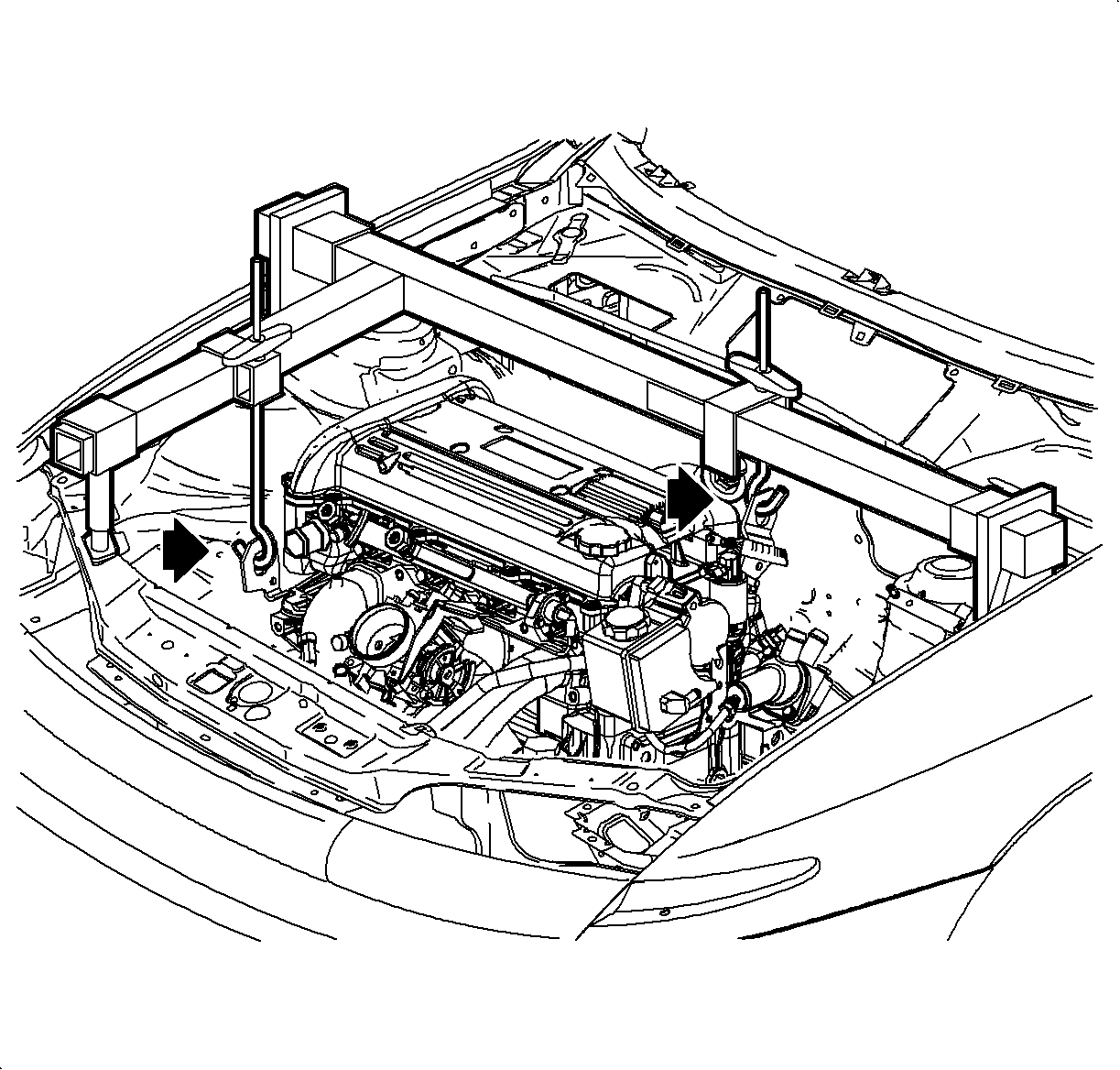
| • | J43405 Engine Support Fixture Adapter |
| • | J 43628 Frame Alignment Fixture |
| • | SA9105E Engine Support Bar Assembly |
| • | SA91112T Axle Seal Protector |
Removal Procedure
- Position the vehicle on a hoist.
- Remove the battery.
- Disconnect the battery feed to the underhood fuse block (UHFB).
- Disconnect the coolant hose from the UHFB.
- Release the retaining tabs on the UHFB cover and remove.
- Release the retaining tabs (2) on the UHFB and roll the fuse block back (1) to access the electrical connectors.
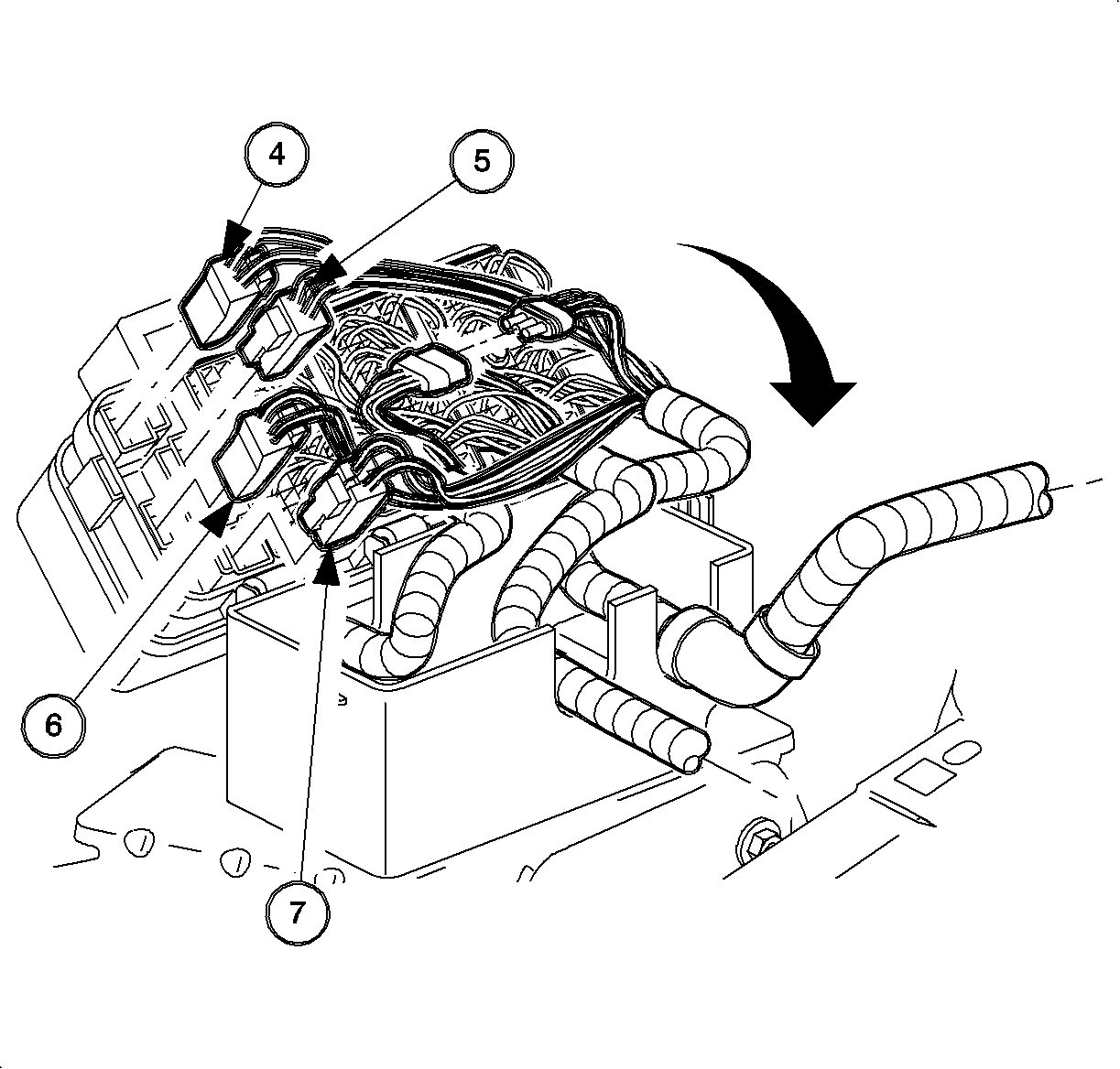
- Remove the following connectors from the UHFB:
- Lift the fuse block off the case.
- Remove the harnesses from the UHFB case.
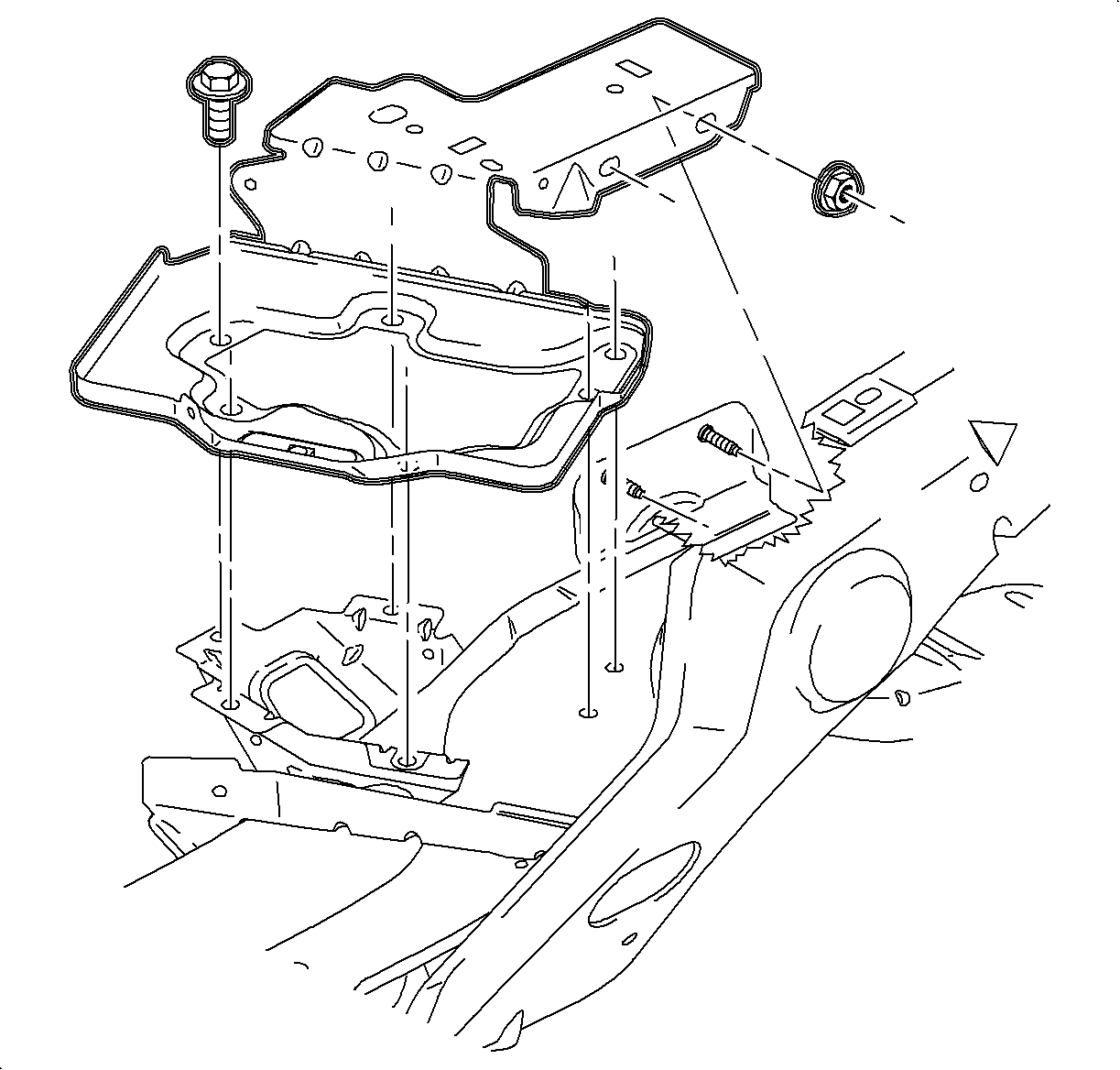
- Remove the UHFB case fastener, and remove the case from the battery tray.
- Remove the battery tray fasteners and the battery tray.
- Remove clamp from AIR. hose behind the cooling fan.
- Separate the AIR tube from the hose and push the tube back towards the transaxle.
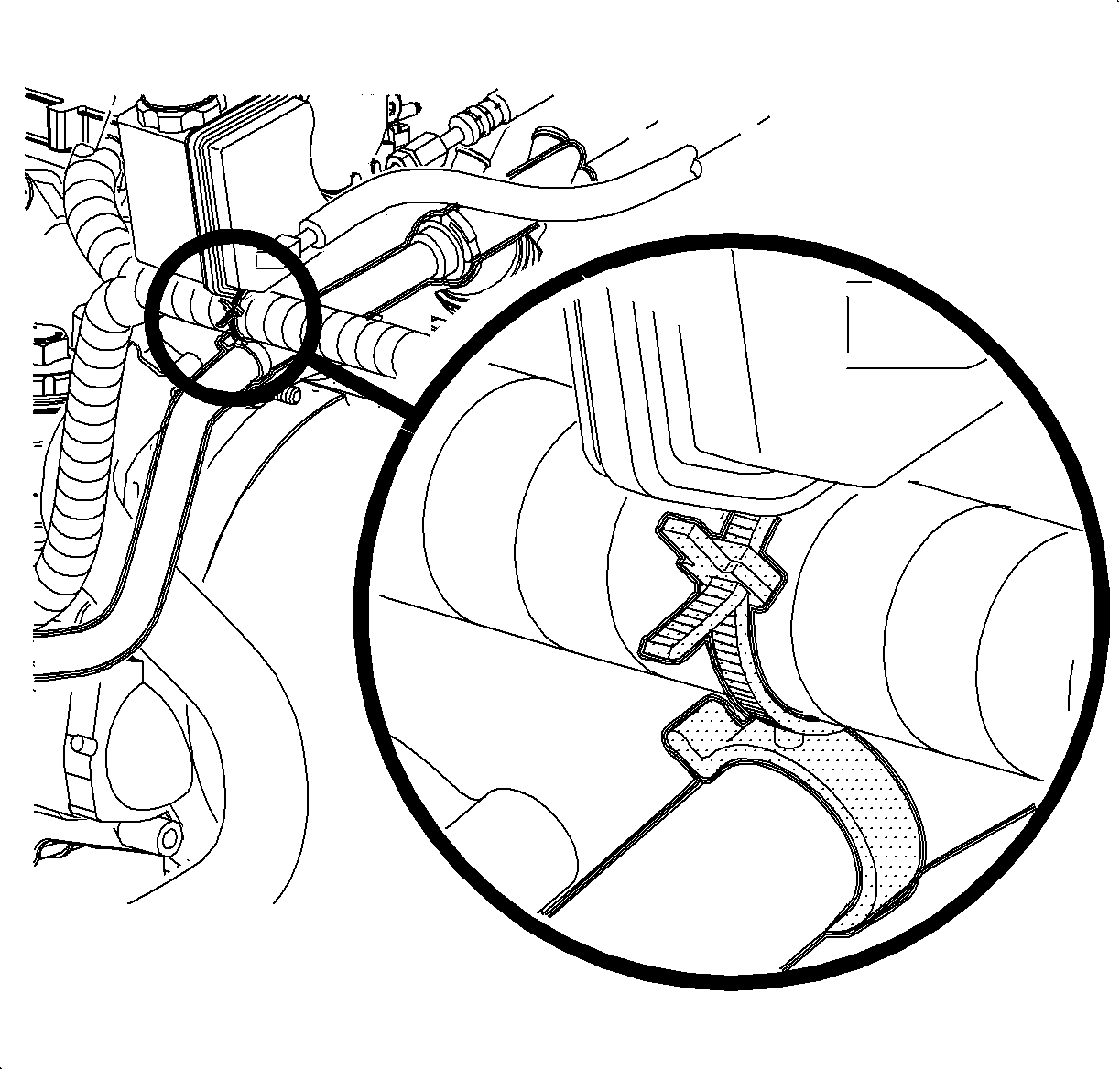
- Remove the hose clip holding the 2 power steering lines together.
- Loosen the pinch bolt securing the control assembly rod to control shaft lever assembly.
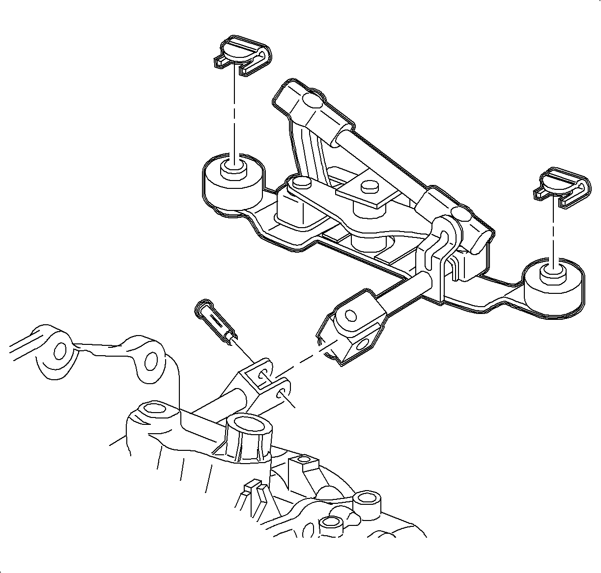
- Remove the pin retaining control shaft lever to shift control shaft of the transaxle.
- Remove the retaining clips holding the control shaft lever assembly to transaxle and frame assembly brackets.
- Remove the control shaft lever assembly by pulling straight up off the pivot pins.
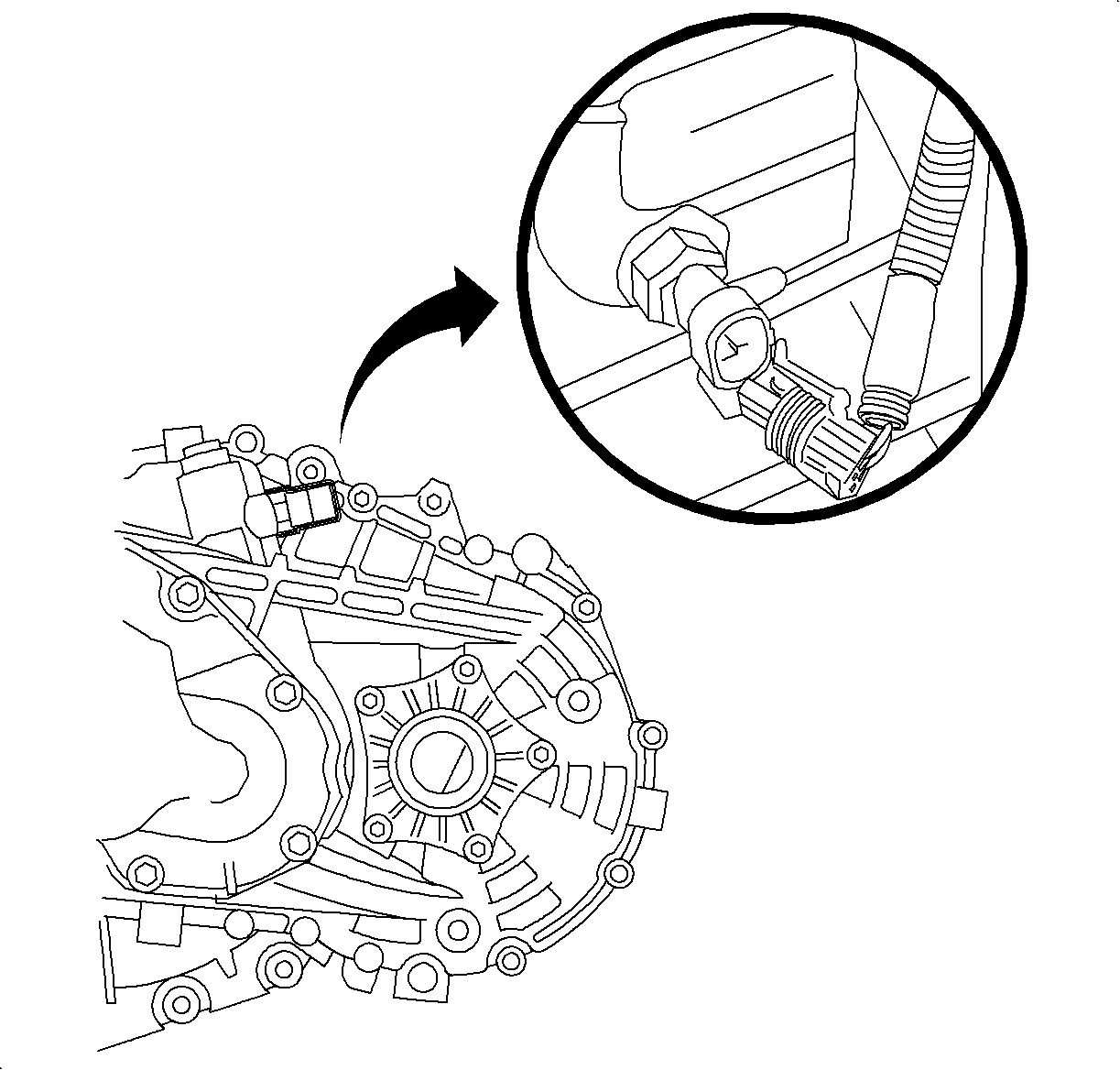
- Disconnect the back-up lamp switch electrical connector.
- Remove the wire harness from the transaxle.
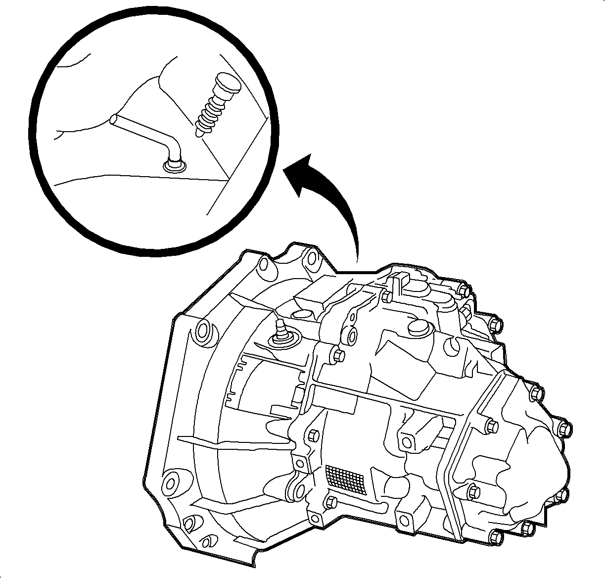
- There is a hole on top of the transaxle that will have either a spring loaded locking pin or a hole plug.
- Remove the clutch hydraulic fitting from the transaxle. Elevate and secure the fitting to prevent excessive loss of brake fluid.
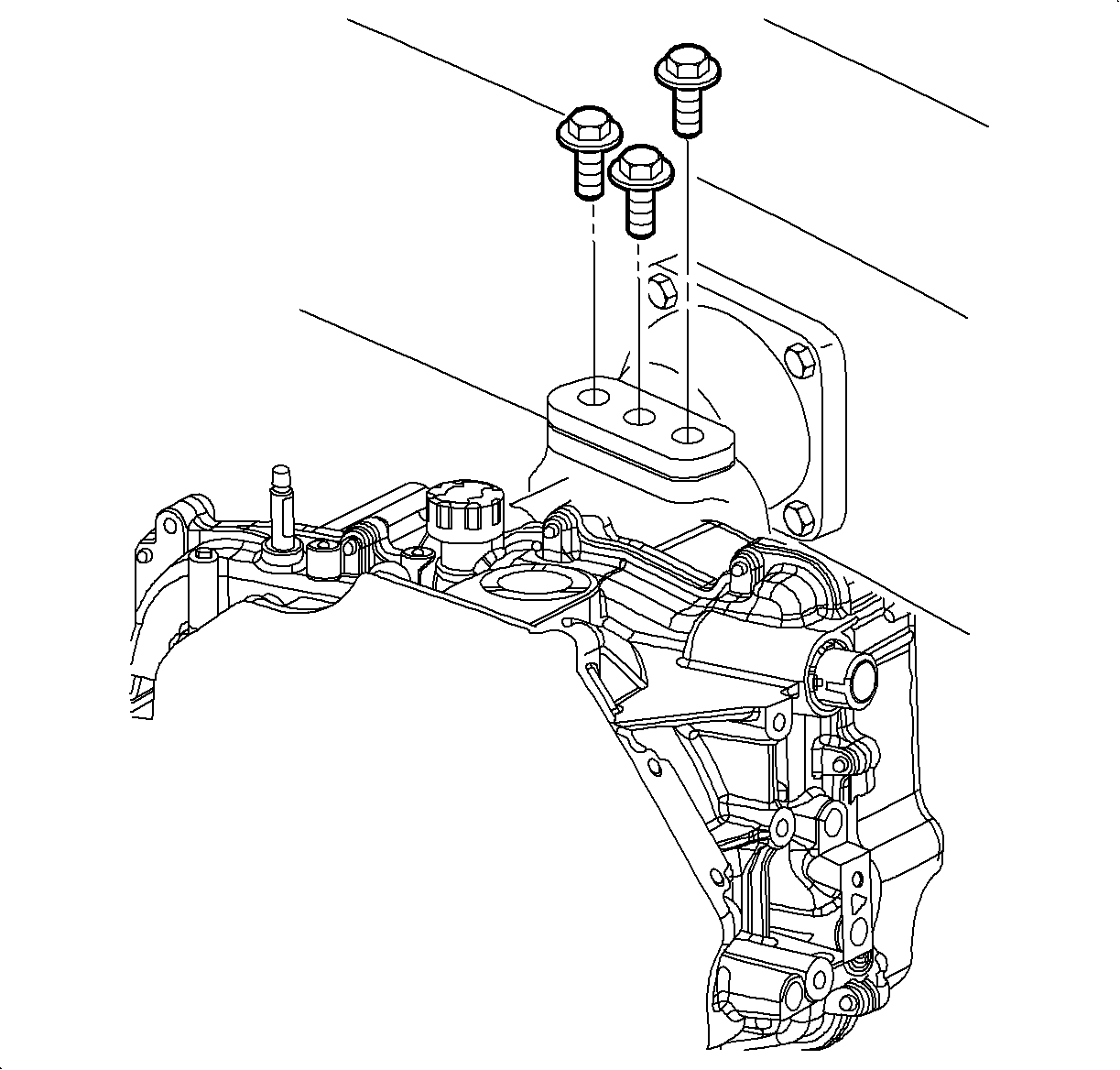
- Remove the upper transaxle-to-engine mounting bolts.
- Install the SA9105E with the adapter kit J43405 as shown.
- Mark the position of and remove the left transaxle mount bolts.
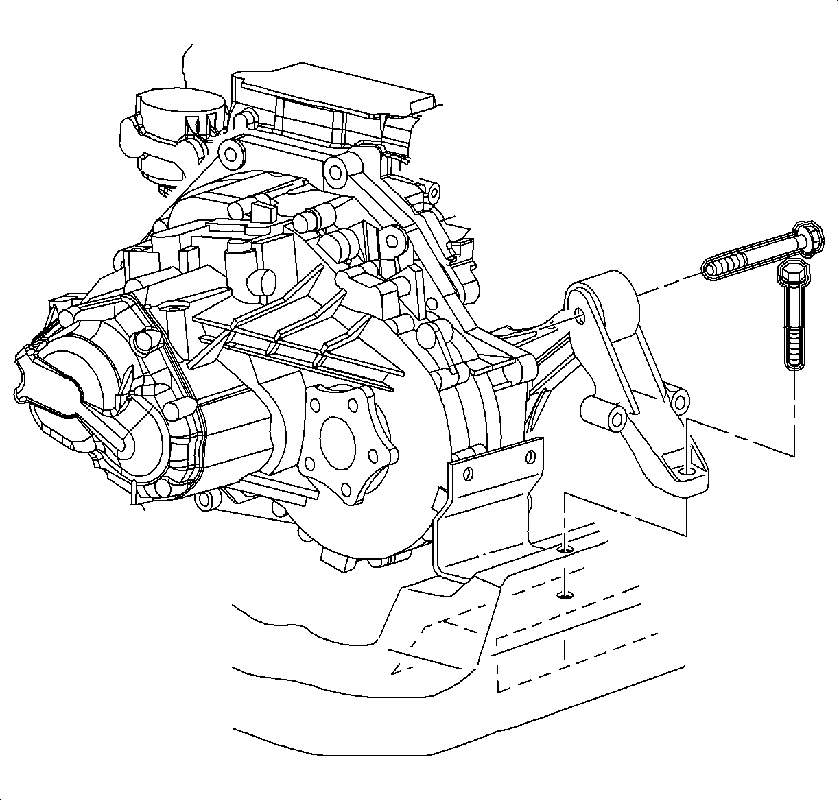
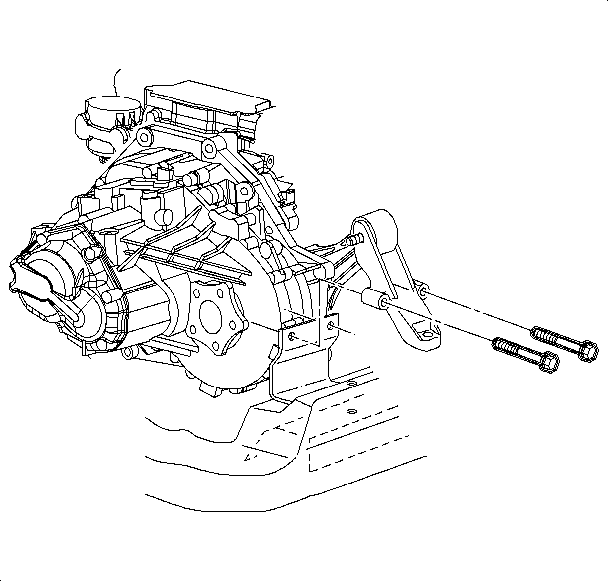
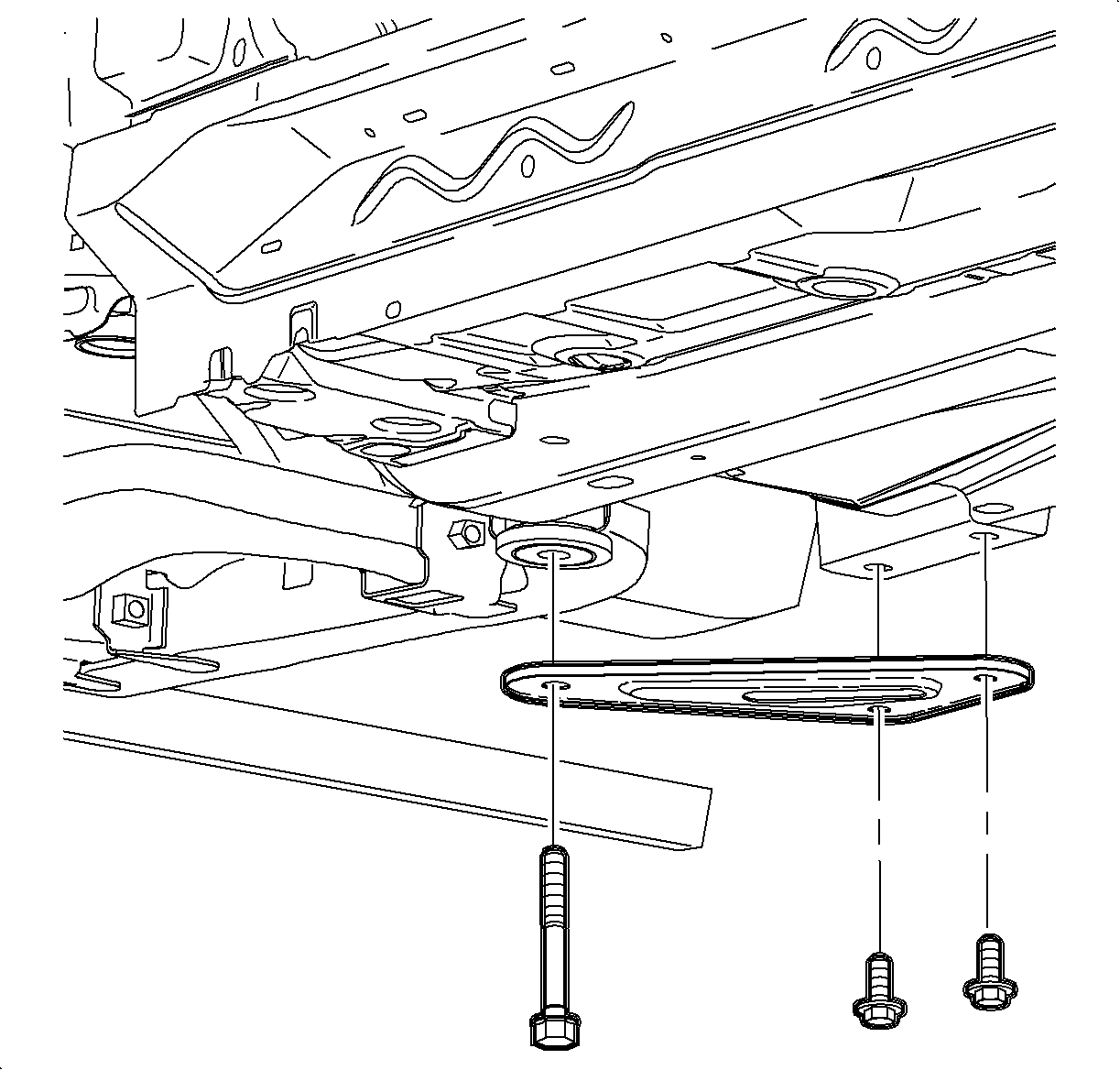
- Remove the rear transaxle mount through bolt, and transaxle mount-to-frame bolt.
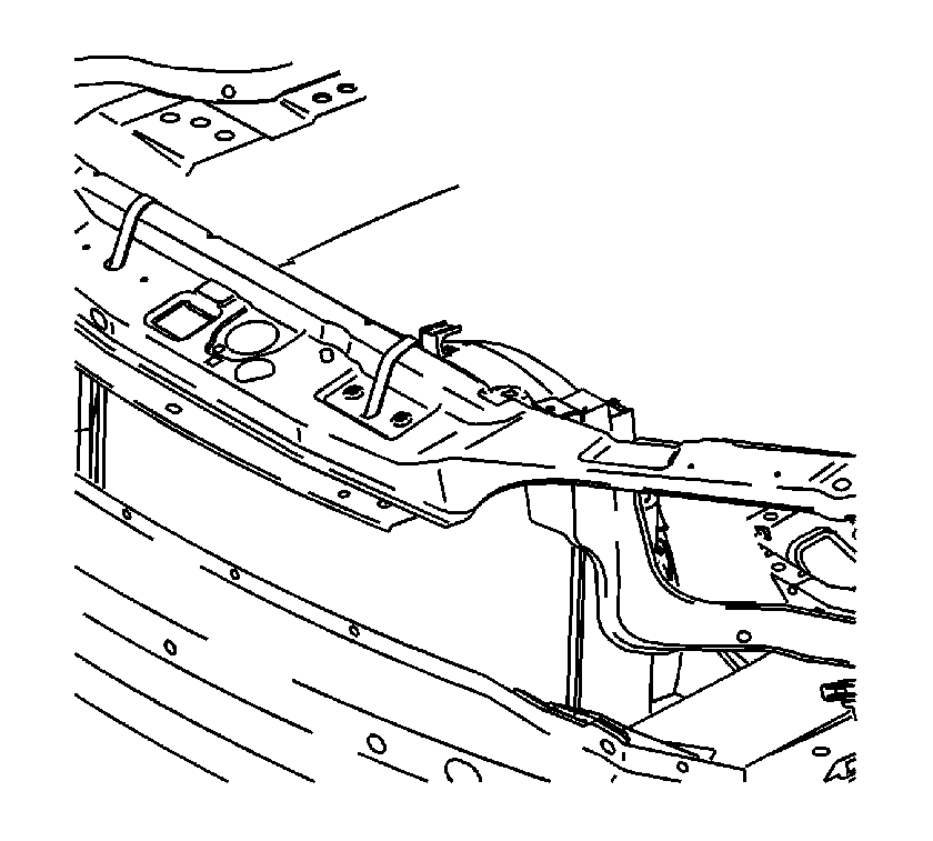
- Fasten the radiator to upper radiator support.
- Raise the vehicle on a hoist.
- Remove the front wheel and tire assemblies.
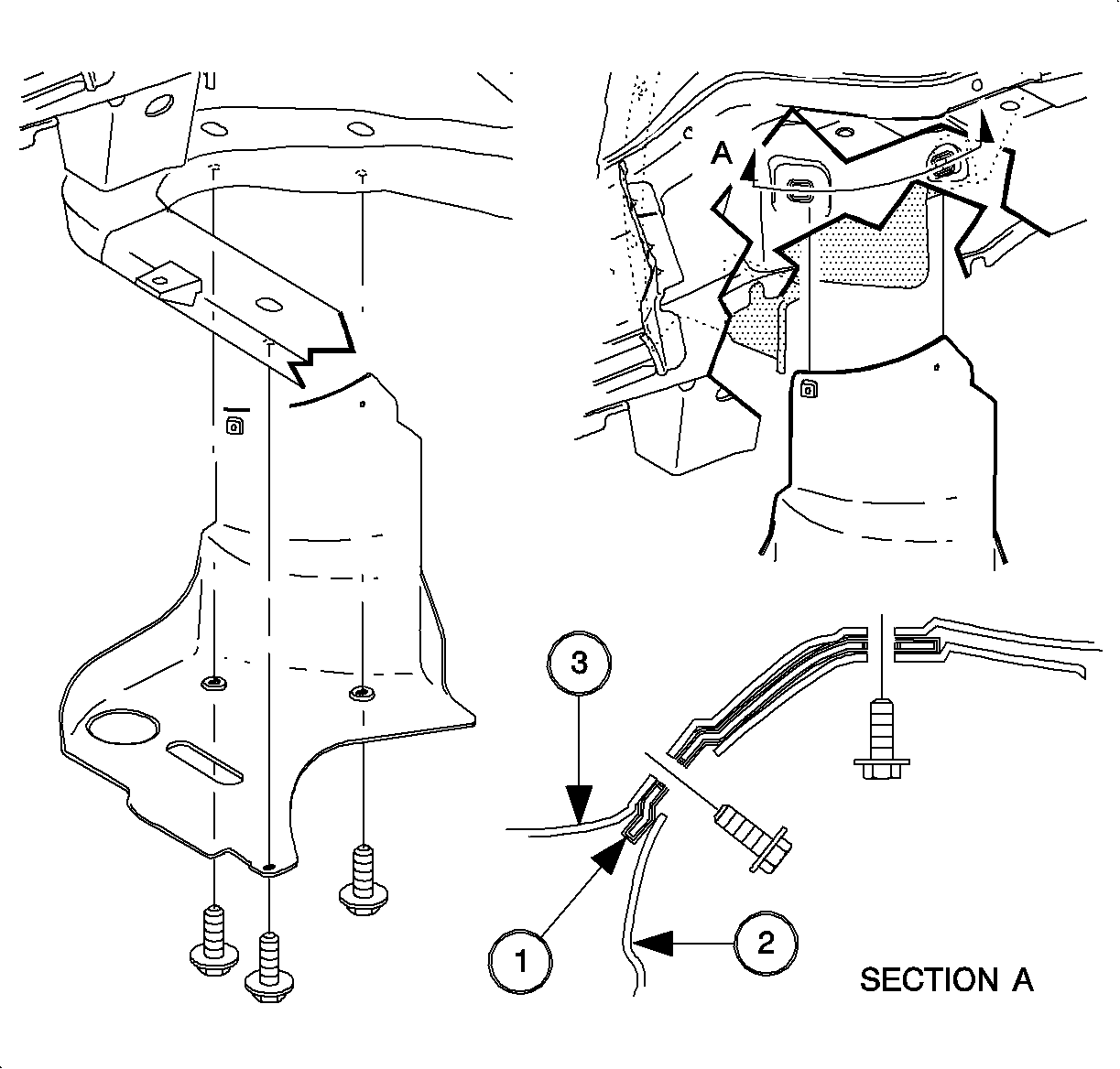
- Remove the right front lower splash shield.
- Remove the left front wheel liner push pin from the frame.
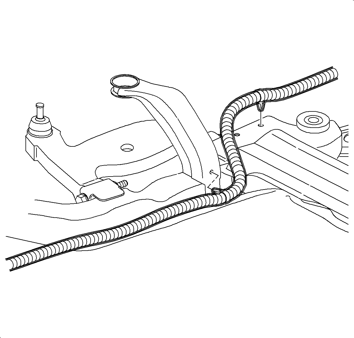
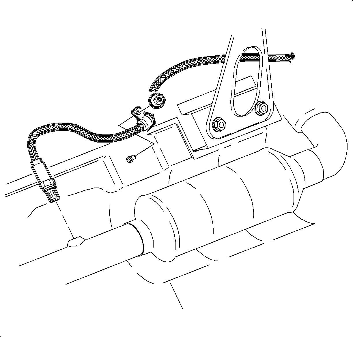
- Disconnect the rear O2 sensor connection, and remove the harness from the frame at 2 attachment points.
- Remove the O2 sensor clamp to underbody attachment nut.
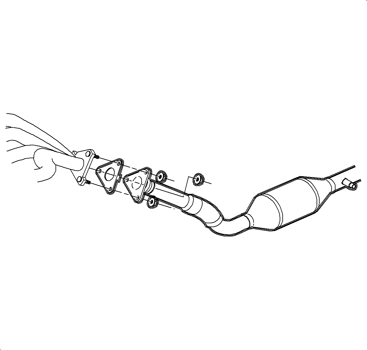
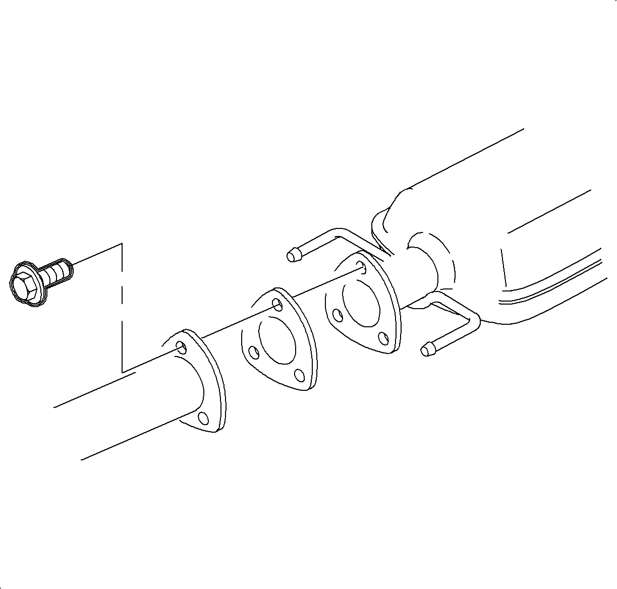
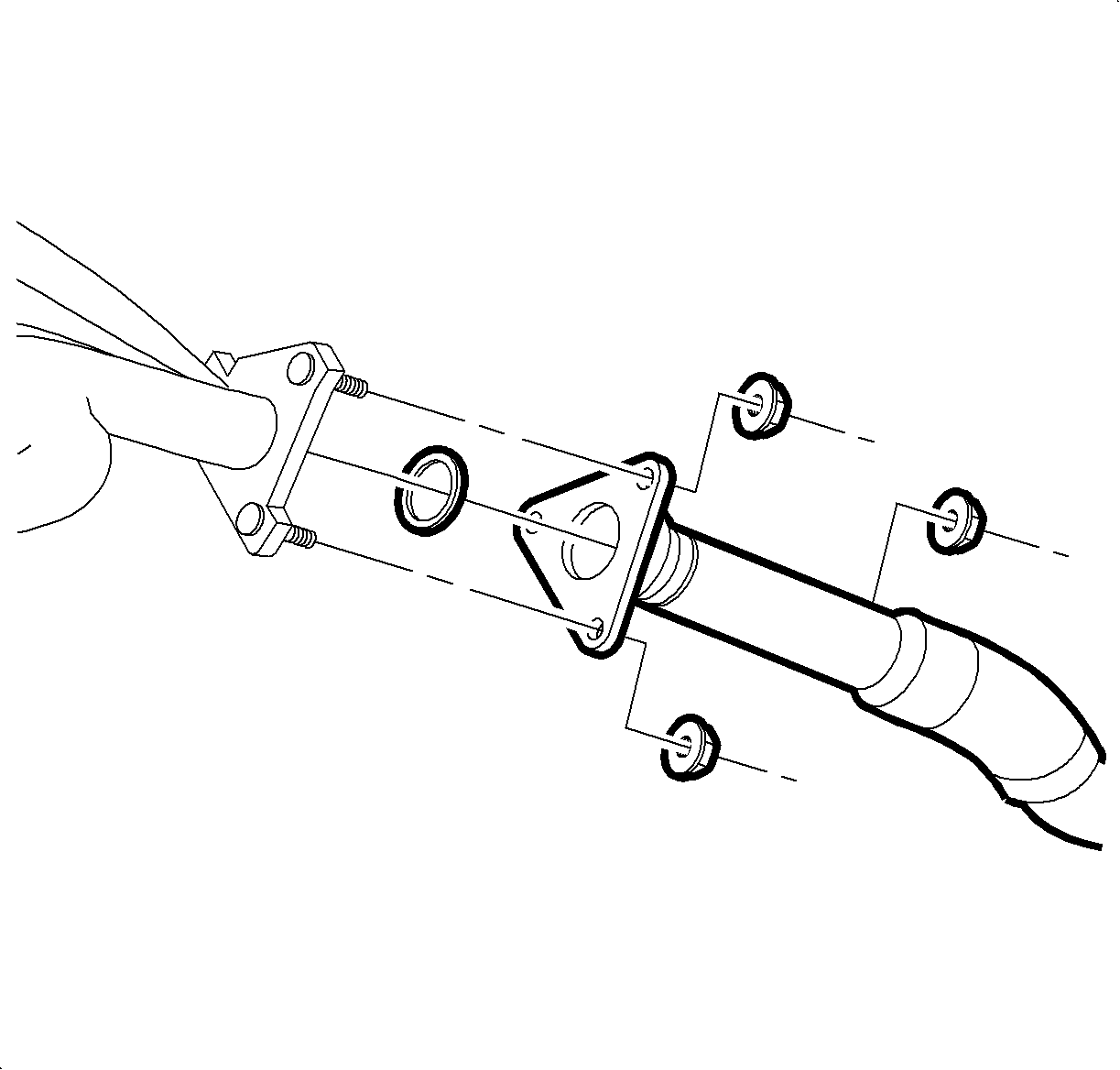
- Remove the exhaust manifold pipe to exhaust manifold nuts. (Automatic shown, manual similar.)
- Remove the exhaust manifold pipe to exhaust resonator pipe bolts.
- Remove the exhaust manifold pipe.
- Remove the front transaxle mount through bolt.
- Remove the remaining rear transaxle mount-to-frame bolts.
- Remove the rear transaxle mount.
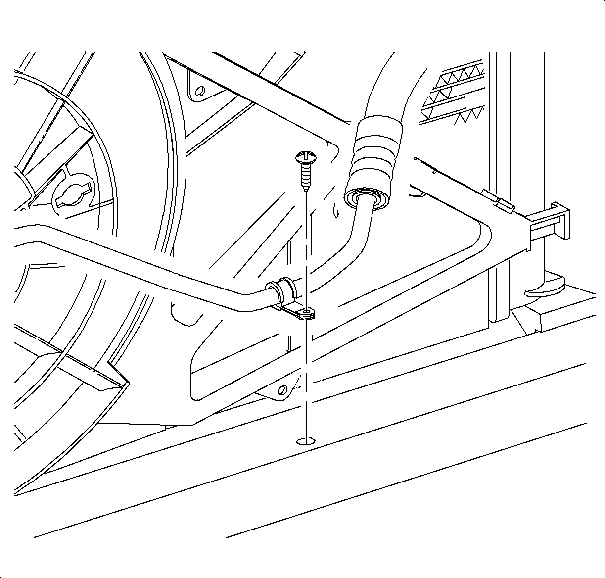
- Remove the A/C line to frame attachment clip at the front of the vehicle.
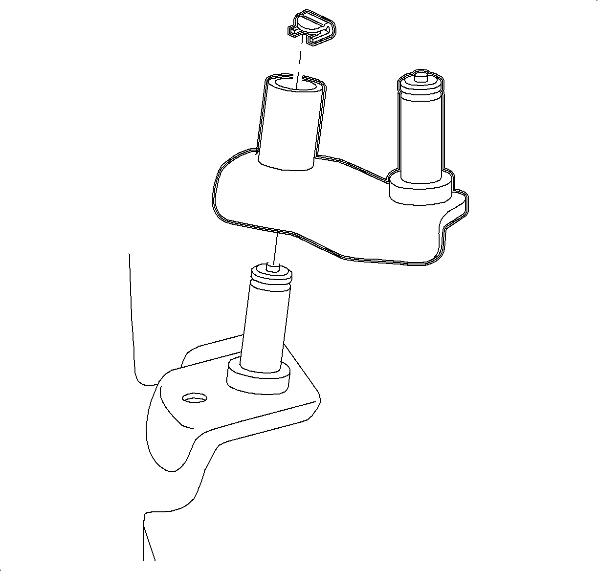
- Remove the frame-to-shifter link pivot pin clip.
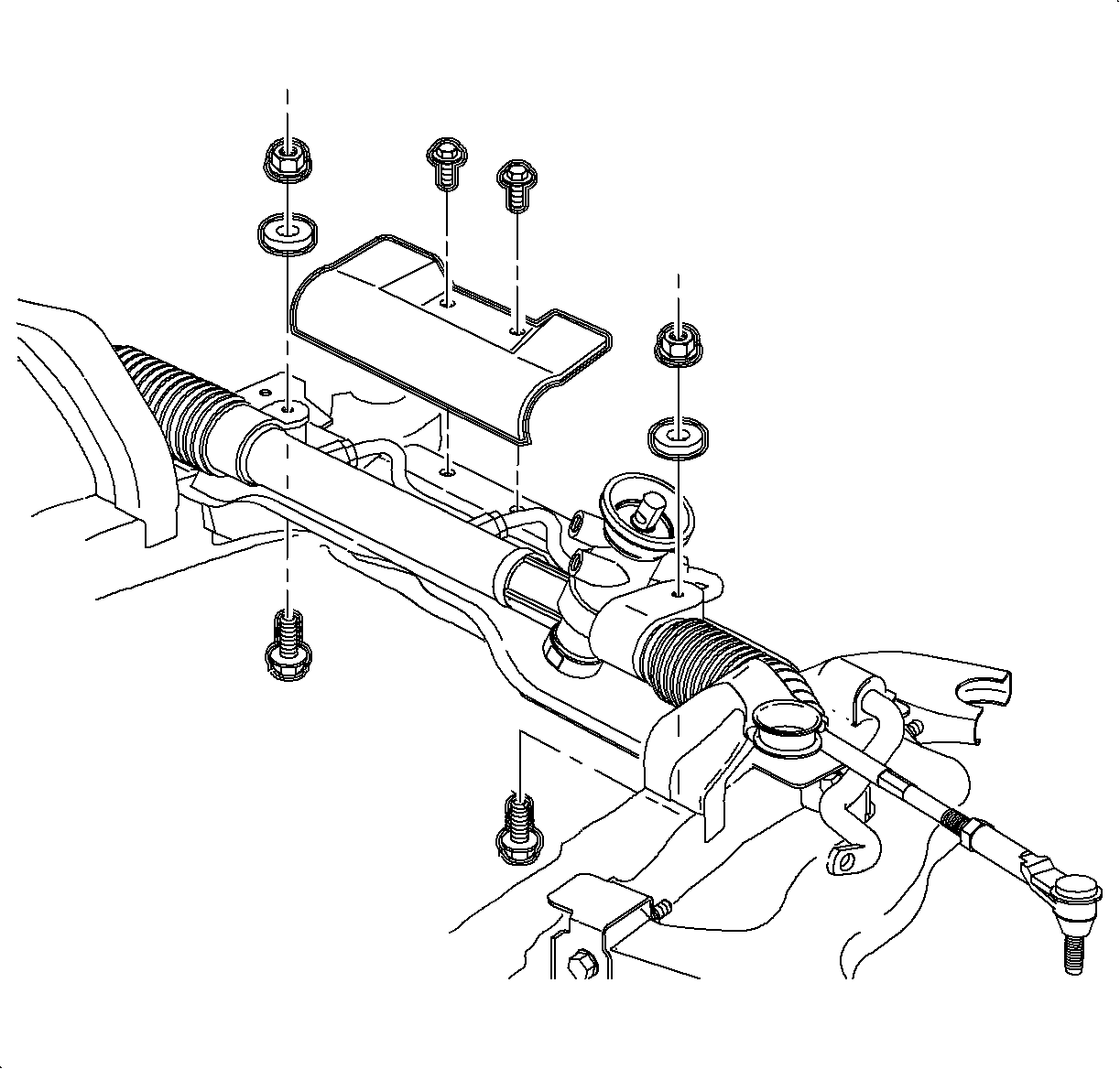
- Remove the steering gear-to-frame assembly bolts. (Automatic shown, manual similar.)
- Using mechanics wire, secure the steering gear assembly to the body of the vehicle.
- Remove the stabilizer bar links from the strut assemblies and discard the nuts.
- Remove the lower ball stud bolt and separate the ball stud from the steering knuckle assembly.
- Remove the suspension support assemblies.
- Remove the suspension support cage nuts from the body. Discard the cage nuts and support bolts. New nuts and bolts must be used for assembly.
- Using the powertrain lifting table and J 43628 , support the frame assembly.
- Remove the remaining 4 frame-to-body attachment fasteners.
- Carefully lower the frame assembly from the vehicle.
- Remove the frame assembly cage nuts from the body.
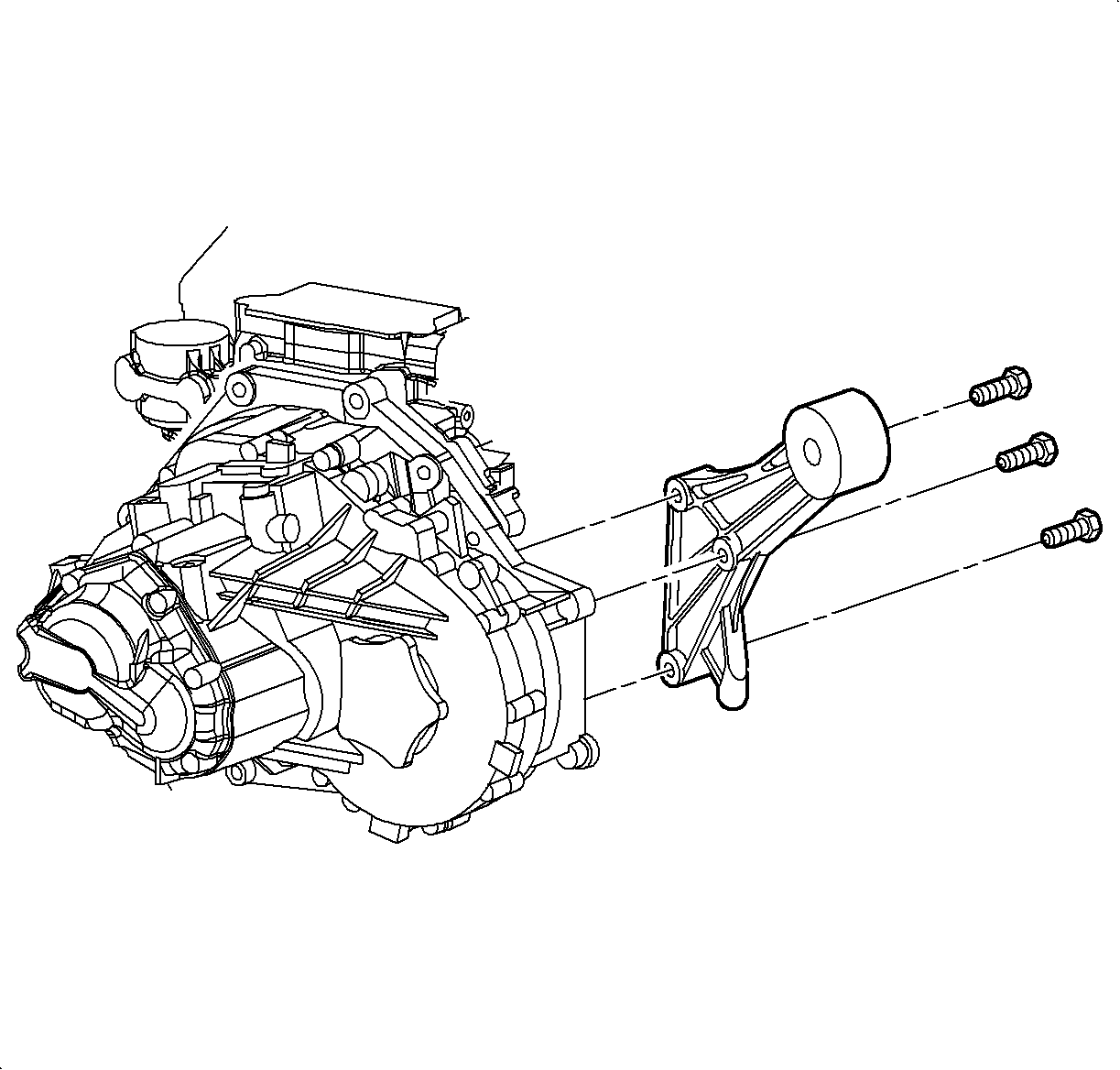
- Remove the front transaxle mount from the transaxle.
- Remove the rear transaxle mount from the transaxle.
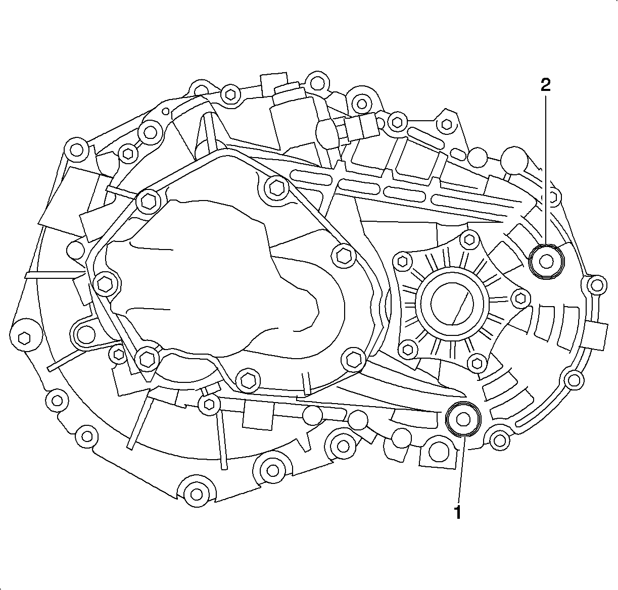
- Drain the transaxle fluid by removing the transaxle drain plug (1).
- Use a pry bar to remove the axle shafts from the transaxle. Leave the axle shafts in the steering knuckles and secure the axle shafts up and out of way of the transaxle removal path.
- Remove the A/C line retaining clips and drop the A/C line down from the body as shown.
- Lower vehicle.
- Lower the driver side of the powertrain with the SA9105E to allow the transaxle to clear the engine compartment rail.
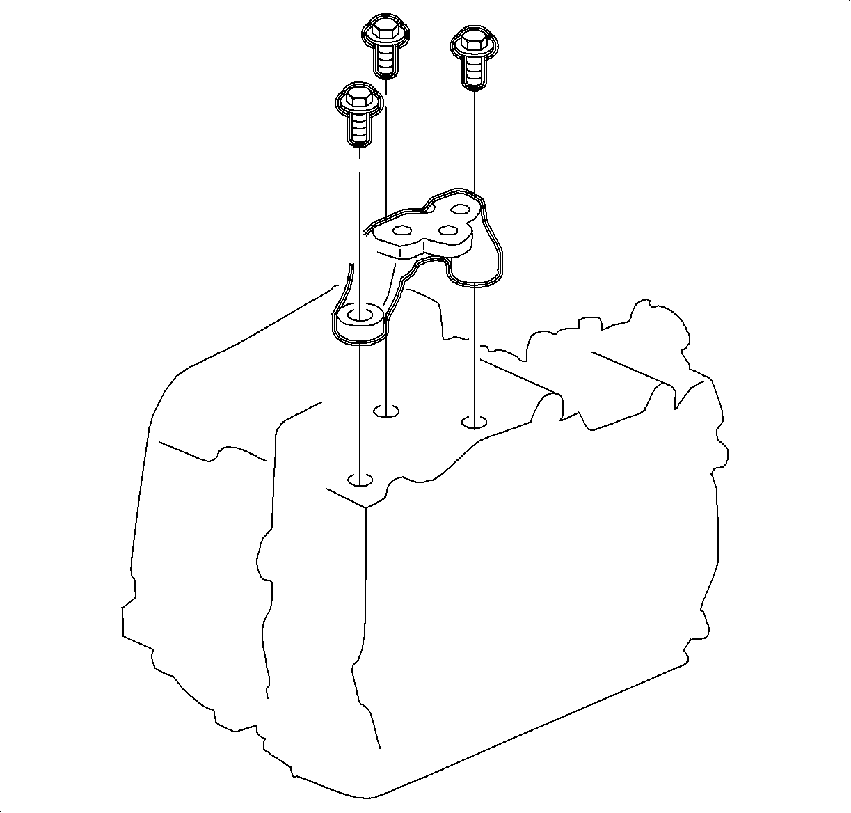
- Remove the left transaxle mount bracket from the transaxle.
- Raise the vehicle.
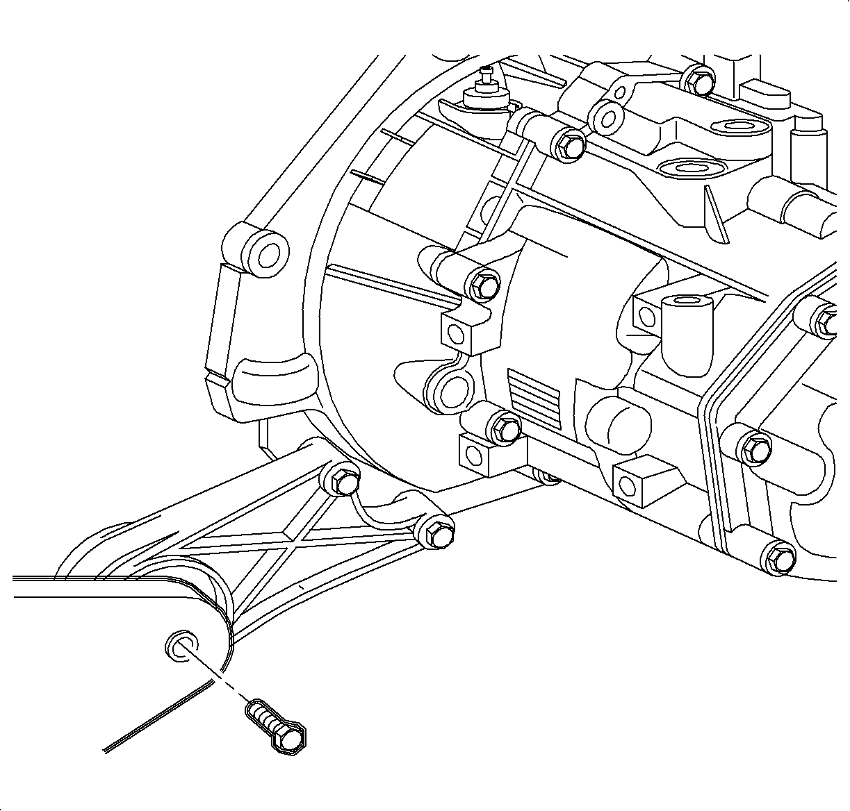
- Remove the control shaft lever assembly pivot pin bracket from the transaxle case.
- Support the transaxle securely with the transmission jack.
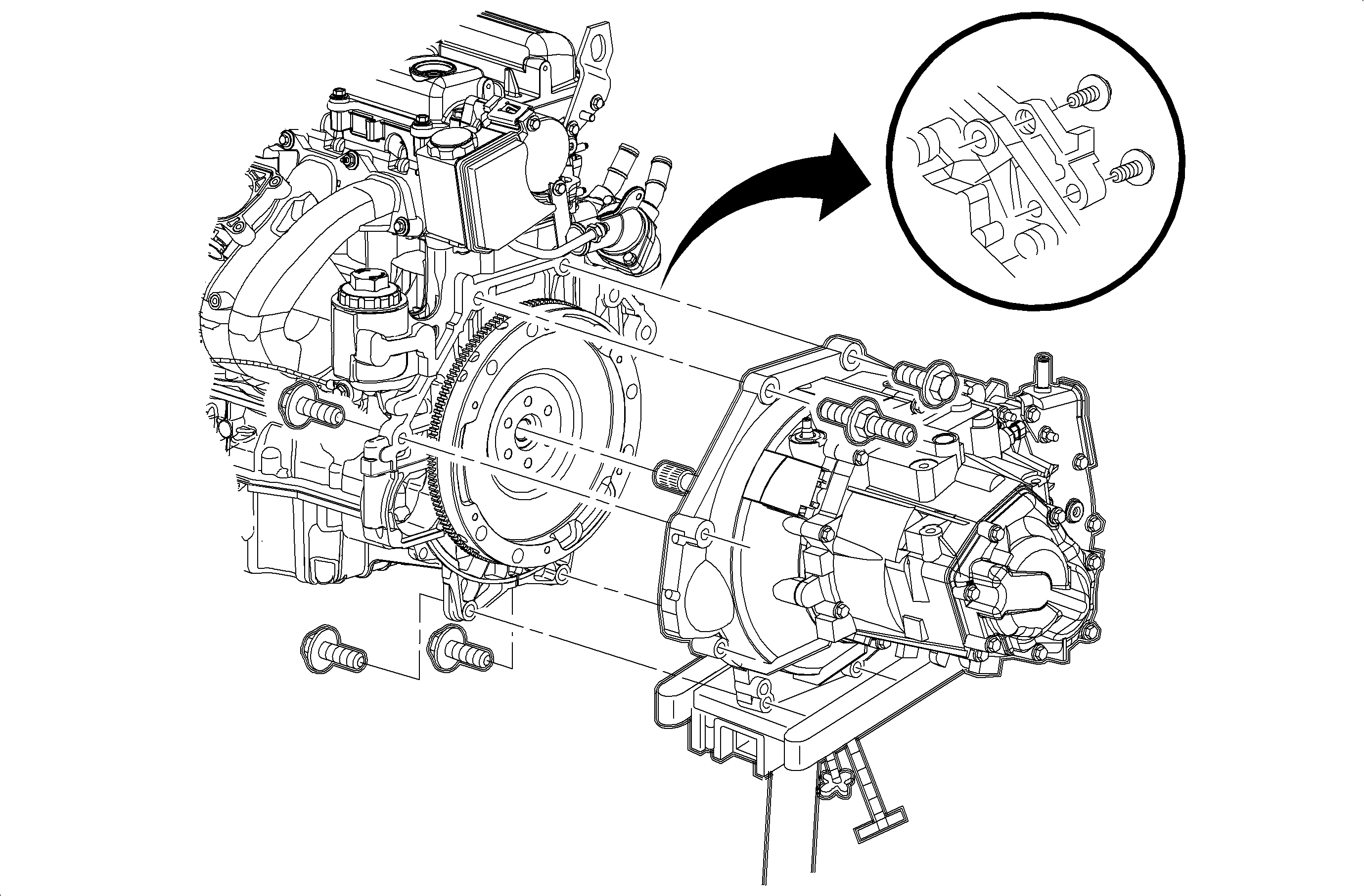
- Remove the remaining engine-to-transaxle mounting bolts.
- Separate the transaxle from the engine and lower the transaxle from the vehicle.
Caution: Refer to Vehicle Lifting Caution in the Preface section.
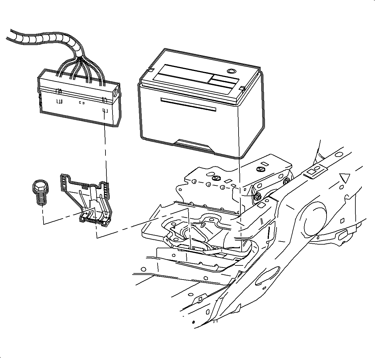
| 2.1. | Disconnect the negative battery cable. |
| 2.2. | Disconnect the positive battery cable. |
| 2.3. | Move the fan control module. Leave the wiring connected, lift the module up and away from the bracket, and position out of the way. |
| 2.4. | Remove the battery hold down bracket. |
| 2.5. | Remove the battery. |
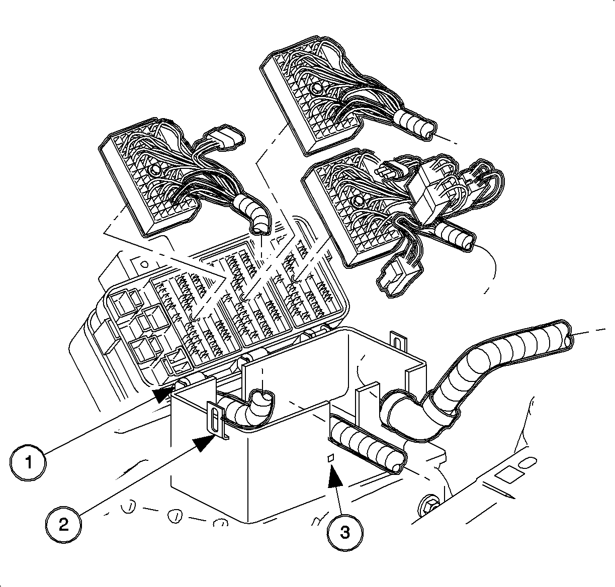
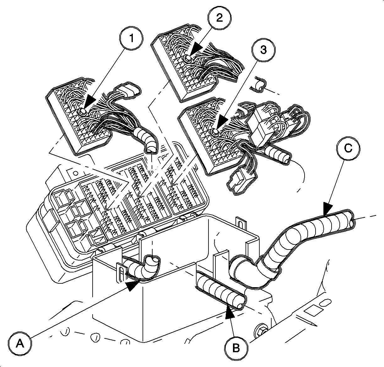
| 7.1. | Engine 68-way (1) |
| 7.2. | Forward lamp 68-way (2) |
| 7.3. | I/P 68-way (3) |
| 7.4. | Forward lamp 2-way (White) (4) |
| 7.5. | I/P 2-way (Black) (5) |
| 7.6. | I/P 2-way (Green) (6) |
| 7.7. | I/P 2-way (Brown) (7) |
Important: There are 2 tabs that hold the hard shell grommets in place at the bottom of the grommet. Disengage the tabs to remove the grommet from the case.
| • | Engine (A) |
| • | Forward Lamp (B) |
| • | Instrument Panel (I/P) (C) |
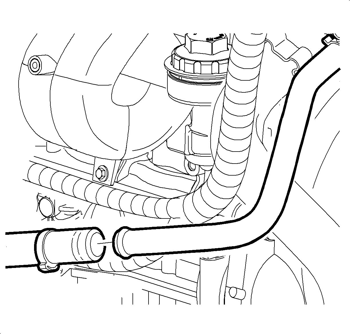
Important: Note the original position of the AIR components.
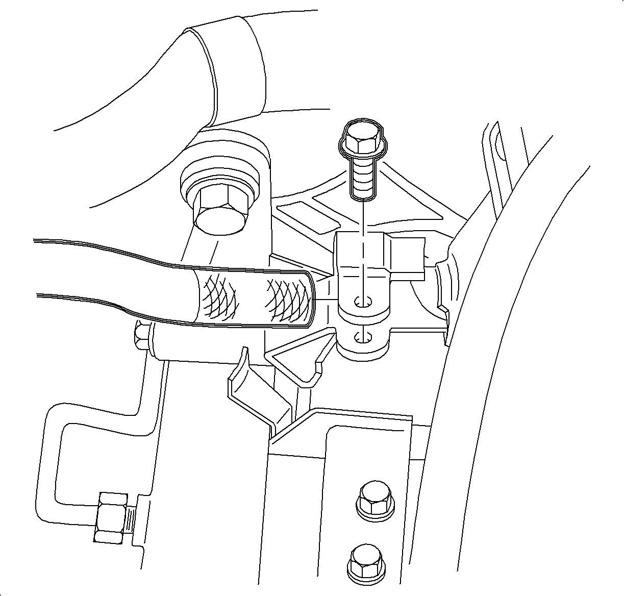
Notice: The control shaft lever retaining pin has a spring loaded locking feature securing the pin in place. If this spring is not depressed before attempting to remove the pin, damage to the pin will result.
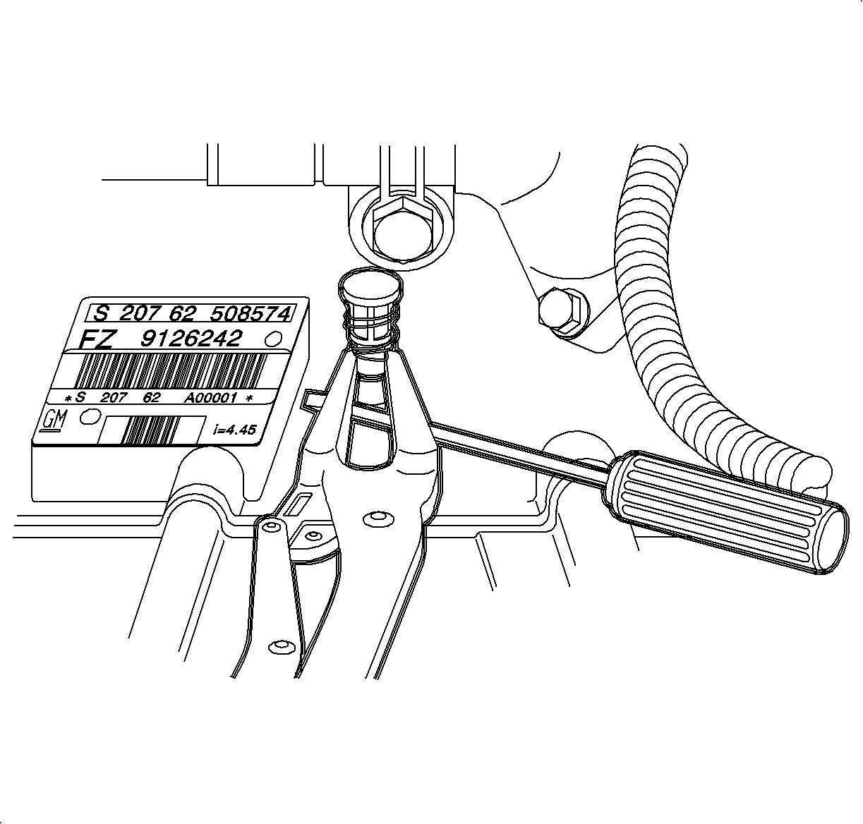
| • | If the hole has a spring loaded locking pin, remove it and discard. A new hole plug will be installed. |
| • | If the hole has a hole plug, remove it and retain for reuse. |
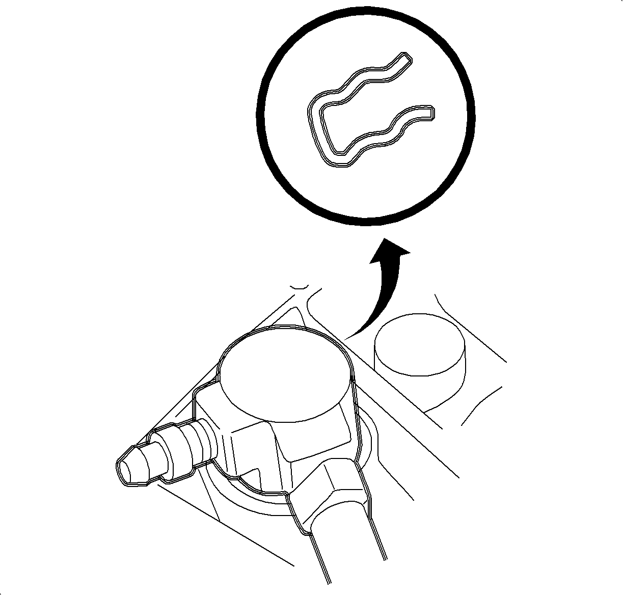
Caution: Refer to Vehicle Lifting Caution in the Preface section.
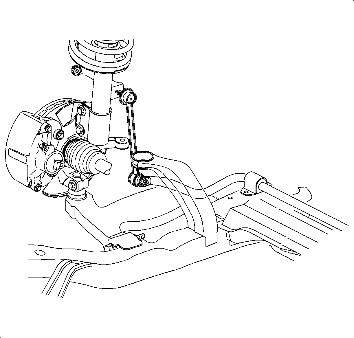
Notice: Hold the ball stud from turning when removing/installing the nut. The boot can become torn and damaged if the ball stud turns.
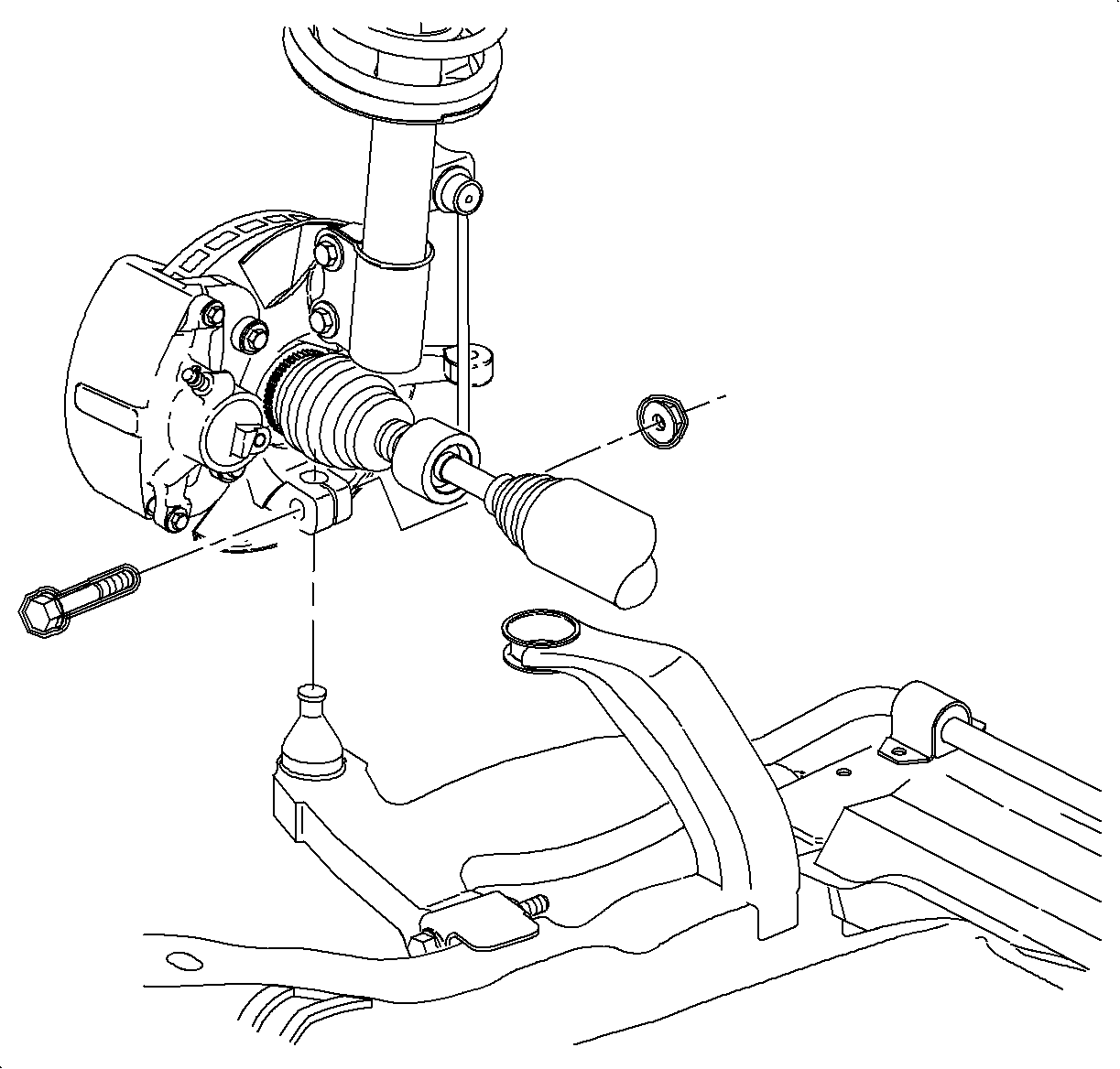
Notice: Do not attempt to separate ball studs with a wedge type separator tool because seal may be damaged.
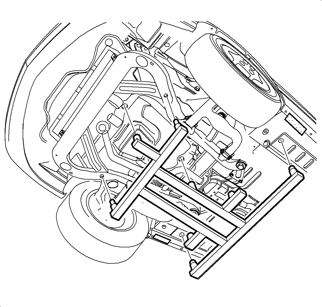
Important: Discard the cage nuts and frame bolts. New nuts and bolts must be used during assembly.
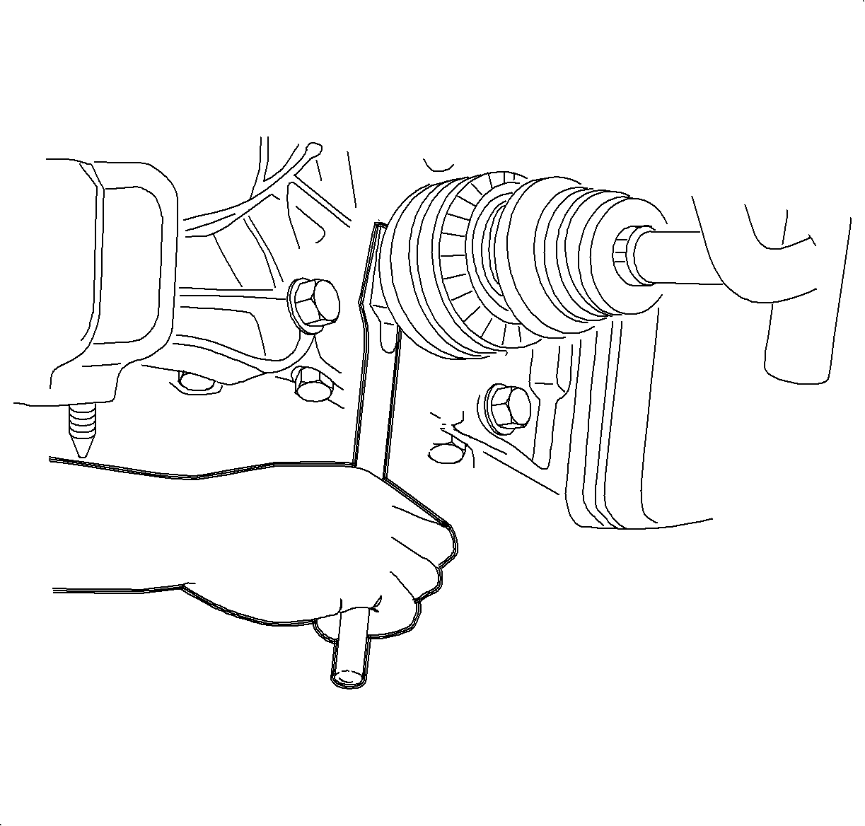
Notice: To prevent damage to CV Joint boots, be careful not to allow them to contact other parts during the removal/installation process. Also, never pull on the shaft assembly.
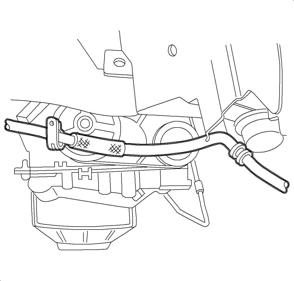
Notice: If the A/C line is not removed and lowered from the body prior to lowering the powertrain, the engine crankshaft pulley will damage the A/C line possibly causing a Freon leak to occur.
Installation Procedure
- Securely place the transaxle on the transmission jack. Place the transaxle in any gear.
- Raise the transaxle into the vehicle and align the transaxle input shaft to the center of the clutch disc. Guide the transaxle into position. Rotate back and forth to align the input shaft splines to the clutch disc.
- Install the lower transaxle-to-engine mounting bolts.
- Remove the transmission jack.
- Install the control shaft lever assembly pivot pin bracket onto the transaxle case.
- Using the , insert the axle shafts into the transaxle. After the splines clear seal protector but before snapping the axle into place, remove the seal protector.
- Ensure the transaxle drain plug is installed in the transaxle case. If it is not installed, clean and apply sealant P/N 21485278 to the threads and install the plug.
- Lower the vehicle.
- Remove the transaxle fill plug from the top of the transaxle. Fill the transaxle with 2 quarts of manual transaxle lubricant P/N 21018899.
- Clean and apply sealant P/N 21485278 to the threads and install the transaxle fill plug.
- Install the left transaxle mount bracket onto the transaxle. (Automatic shown, manual similar).
- Raise the left side of the powertrain to the correct height using the .
- Raise the vehicle.
- Reposition the A/C line against the body and install the A/C line retaining clips.
- Install the rear transaxle mount onto the transaxle.
- Install the front transaxle mount onto the transaxle.
- Install the new cage nuts into the body as the torque retention of the old nuts may not be sufficient.
- Raise the frame assembly to the body.
- Install 4 new frame-to-body bolts.
- Install the new cage nuts into the body for suspension supports. Torque retention of the old nuts may not be sufficient.
- Install the suspension supports using new bolts and tighten all frame bolts.
- Install the ball stud into the steering knuckle.
- Install the frame-to-shifter link pivot pin clip.
- Install the steering gear-to-frame using new bolts and nuts. (Automatic shown, manual similar).
- Install the stabilizer bar links-to-strut assemblies using new nuts.
- Inspect the rubber boots for damage and replace the part if damaged.
- Install the rear transaxle mount.
- Install the rear transaxle mount-to-frame bolts.
- Install the front transaxle mount through bolt.
- Position the gasket on the manifold pipe.
- Position the manifold pipe into the vehicle.
- Install the exhaust manifold pipe to exhaust manifold nuts.
- Install the exhaust manifold pipe to exhaust manifold nuts. (Automatic shown, manual similar).
- Position the gasket between the manifold pipe and resonator.
- Install the exhaust manifold pipe to resonator bolts and tighten.
- Tighten the exhaust manifold pipe to exhaust manifold nuts.
- Attach the A/C line clip to the front of the frame assembly.
- Install the right front lower splash shield.
- Install the left front wheel liner push pin to the frame.
- Install the O2 sensor clamp to the underbody attachment nut.
- Connect the O2 sensor electrical connector and attach the harness to the frame.
- Install the wheel and tire assemblies onto the hub.
- Install the wheel bolts and tighten is a star pattern.
- Install the remaining rear transaxle mount-to-frame bolts.
- Install the rear transaxle mount through bolt.
- Perform the vehicle alignment. Refer to "Alignment" in the "Alignment, Wheels and Tires" section of the Chassis Service Manual.
- Lower the vehicle.
- Install the upper transaxle-to-engine mounting bolts.
- Reference the alignment marks made during disassembly and install the left transaxle mount bolts.
- Remove the and the J-43405 .
- Install the back-up lamp switch electrical connector.
- Install the wire harness onto the transaxle.
- Install the control shaft lever assembly onto the pivot pin brackets.
- Install the retaining clips to hold the control shaft lever assembly to the transaxle and frame assembly brackets.
- Install the pin to retain the control shaft lever to shift control shaft of the transaxle.
- Rotate the transaxle shift control shaft clockwise, toward the passenger side of the vehicle, and install the into the hole in the top of the transaxle.
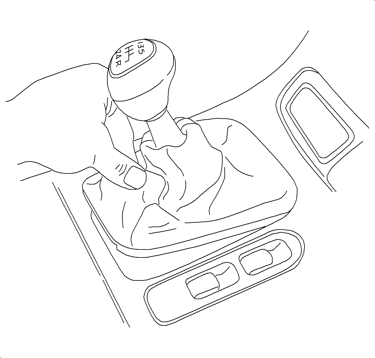
- Pull up the control lever assembly boot to disengage from the console.
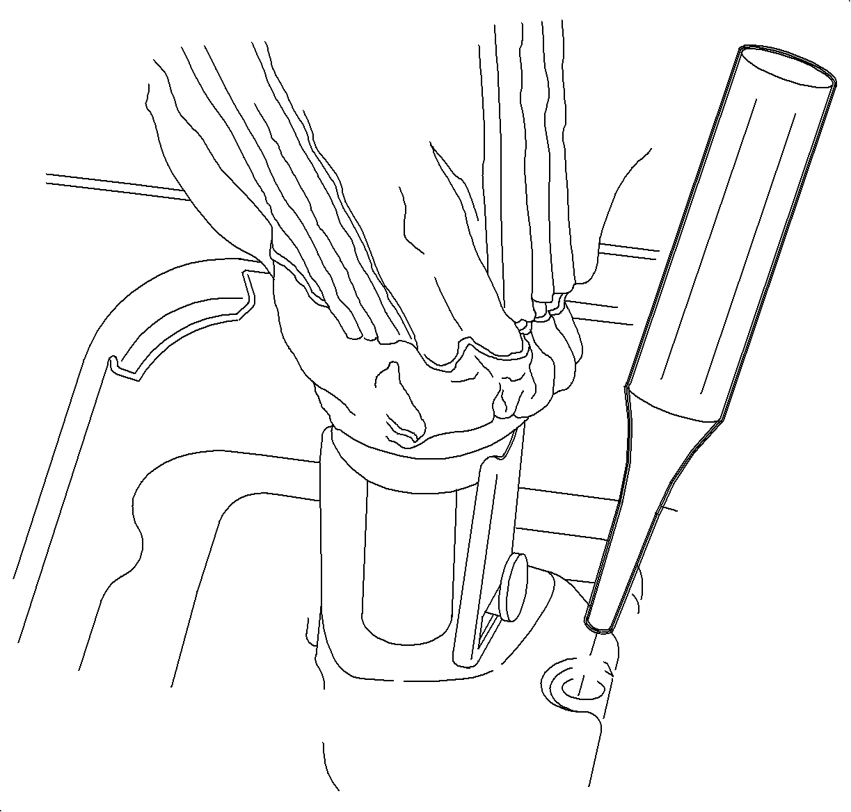
- Move the shift lever to the 5th/Reverse Gate and use a 3/8 in. punch to hold in place.
- Tighten the pinch bolt securing control assembly rod to control shaft lever assembly.
- Remove the from the transaxle and install the shift lever hole plug.
- Install the clutch hydraulic fitting onto the transaxle.
- Bleed the clutch hydraulic system. Refer to "Clutch Hydraulic Bleeding" procedure in this service manual.
- Install the hose clip to the tow power steering lines.
- Pull the AIR tube back to the original position.
- Insert the tube into the hose and install the clamp.
- Ensure the stand-off clip between the AIR tube and the wiring harness is installed correctly.
- Install the battery tray fasteners and the battery tray.
- Install the underhood fuse block (UHFB) case to battery tray and install the bolt.
- Install the air harness to UHFB case. The wire harness grommets have retaining tabs that lock into the case (3) when the harnesses are fully installed.
- Snap the fuse block onto the fuse block case hinges (1).
- Install the following connectors to the UHFB:
- Secure the UHFB to the fuse block case by rotating down and snapping into place.
- Install the UHFB cover.
- Install the coolant hose into place on the fuse block.
- Install the battery feed to the underhood fuse block.
- Install the battery.

Important: Make sure the input shaft splines line up with the clutch disc splines before tightening the transaxle-to-engine mounting bolts. Do not use the bolts to pull the transaxle up to the engine.
Tighten
Tighten the transaxle-to-engine bolts to 65 N·m (48 lb ft).
Tighten
Tighten the control shaft lever pivot pin bracket-to-transaxle bolts to 24 N·m
(18 lb ft).
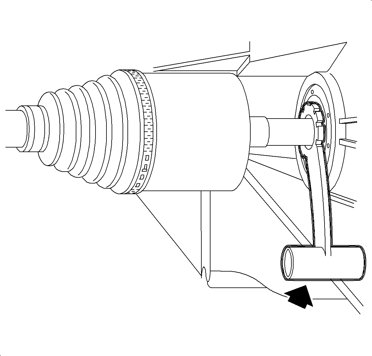
Tighten
Tighten the transaxle drain plug to 50 N·m (37 lb ft).
Tighten
Tighten the exhaust manifold pipe-to-exhaust manifold nuts to 50 N·m
(37 lb ft).

Tighten
Tighten the left transaxle mount bracket-to-transaxle bolts to 55 N·m
(41 lb ft).


Tighten
Tighten the rear transaxle mount-to-transaxle to 55 N·m(41 lb ft).
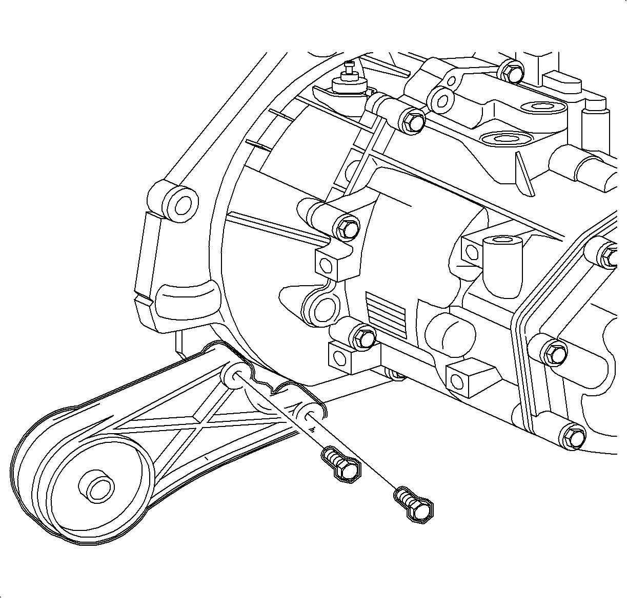
Tighten
Tighten the front transaxle mount-to-transaxle to 55 N·m (41 lb ft).

Important: Be sure the frame alignment tool fully engages in all gage holes.
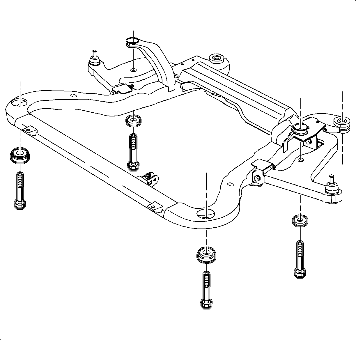
Important: Do not tighten the fasteners at this time.

Tighten
Tighten the frame-to-body bolts to 90 N·m (60 lb ft) + 45°
to 60°.

Tighten
Tighten the ball stud into the steering knuckle to 100 N·m (74 lb ft).


Tighten
Tighten the steering gear-to-frame 45 N·m (33 lb ft) + 90°.
Tighten
Tighten the stabilizer bar links-to-strut assemblies to 65 N·m
(48 lb ft).
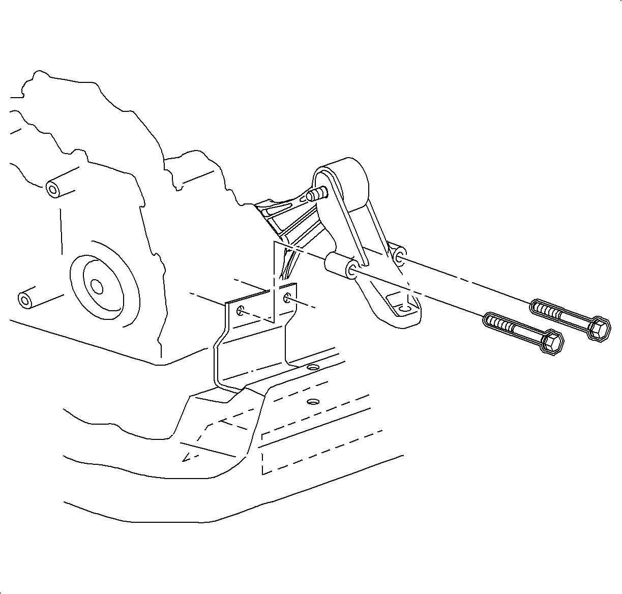
Tighten
Tighten the rear transaxle mount-to-frame bolts to 60 N·m (44 lb ft).
Tighten
Tighten the front transaxle mount through the bolt to 55 N·m(41 lb ft).
Important: Do not tighten the fastener at this time.

Tighten
Tighten the exhaust manifold-to-resonator bolts to 20 N·m (15 lb
ft).
Tighten
Tighten the exhaust manifold pipe-to-exhaust manifold nuts to 30 N·m
(22 lb ft).


Tighten
Tighten the right front lower splash shield-to-frame assembly to 5 N·m
(44 lb in).

Tighten
Tighten the O2 sensor clamp-to-heat shield to 4 N·m (35 lb in).

| 43.1. | Hand tighten all 5 wheel bolts. |
| 43.2. | Use a torque wrench to tighten the wheel bolts using a star pattern. |
Tighten
Initial tighten the wheel bolts to 63 N·m (46 lb ft).
| 43.3. | Use a torque wrench to final tighten the wheel bolts using s star pattern. |
Tighten
Final tighten the wheel bolts to 125 N·m (92 lb ft).
Tighten
Tighten the rear transaxle mount-to-frame bolts to 60 N·m (44 lb ft).
Tighten
Tighten the rear transaxle mount through the bolt to 90 N·m (66 lb ft).
Tighten
Tighten the transaxle-to-engine bolts to 65 N·m (48 lb ft).

Tighten
Tighten the left transaxle mount bolts to 55 N·m (41 lb ft).


Tighten
Tighten the control assembly rod-to-control lever assembly pinch bolt to 12 N·m
(9 lb ft).

Important: The spring loaded locking pin can not be reused. Install a shift lever hole plug.

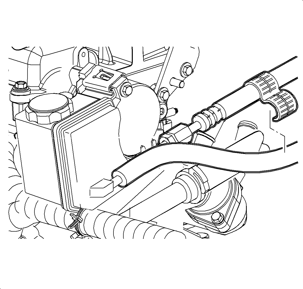

Important: The clamp must be installed with the locking portion facing down.


Tighten
Tighten the battery tray fasteners to 15 N·m (11 lb ft).

Tighten
Tighten the underhood fuse block case bolt to 9 N·m (80 lb in).

| 71.1. | Engine 68 way (1) |
| 71.2. | Forward Lamp 68 way (2) |
| 71.3. | I/P 68 way (3) |
| 71.4. | Forward Lamp 2 way (4) |
| 71.5. | I/P 2 way (Black) (5) |
| 71.6. | I/P 2 way (Green) (6) |
| 71.7. | I/P 2 way (Brown) (7) |

Tighten
Tighten the battery feed cable to underhood fuse block to 16 N·m
(12 lb ft).

| 76.1. | Install the battery onto the battery tray. |
| 76.2. | Install the battery hold down bracket. |
Tighten
Tighten the battery hold down bracket fasteners to 20 N·m (15 lb ft).
| 76.3. | Install the fan control module by sliding down onto the battery hold bracket. |
| Important: The positive battery terminal must be connected first to prevent arcing. |
| 76.4. | Install the positive battery cable. |
Tighten
Tighten the battery cable terminals to 17 N·m (13 lb ft).
| 76.5. | Install the negative battery cable. |
Tighten
Tighten the battery cable terminals to 17 N·m (13 lb ft).
