Tools Required
| • | J 43894 Cockpit Assembly Aid |
| • | J 42578 Steering Wheel Puller |
Removal Procedure
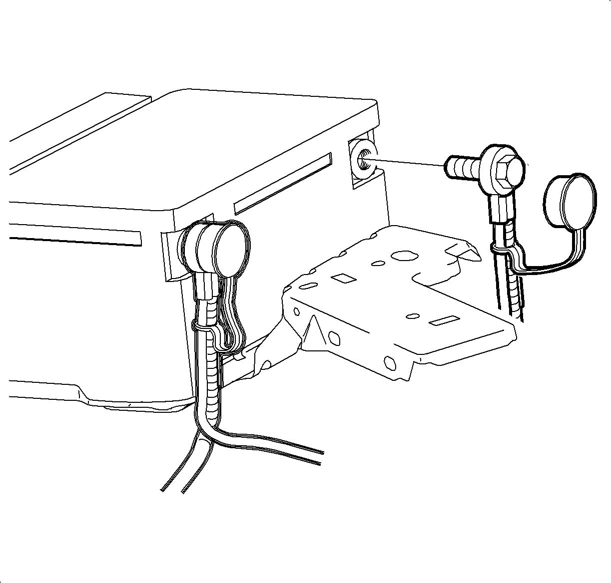
- Disconnect the negative battery cable.
- Recover the refrigerant using an approved refrigerant recovery system. Measure the amount of oil lost during recovery and record the amount.
- Remove the suction/liquid line assembly to TXV retaining nut.
- Remove the suction/liquid line assembly block from the TXV by gently rocking while pulling forward.
- Install a cap on the suction/liquid line assembly to prevent oil spillage.
- Install a cap on the TXV to prevent oil loss and dirt entry.
- Drain the coolant. Refer to CELL LINK Draining Coolant in the Engine Cooling section of the appropriate engine service manual.
- Remove the heater inlet hose:
- Remove the heater return hose:
- Place the end of the heater return hose in a container and apply low pressure 34 kPa (5 psi) of shop air to the heater inlet hose to blow the coolant out of the heater core.
- Install the heater return hose to the nipple and position the clamp at 6 o'clock position on L81, 12 o'clock position on L61.
- Install the heater inlet hose to the auxiliary water pump outlet on L81, or at the thermostat outlet on L61 and position the clamps at 12 o'clock .
- Remove the heater inlet hose from the heater core pipe.
- Remove the heater outlet hose from the heater core pipe.
- Gently pull on the left and right side console extensions to remove the extensions.
- For vehicles equipped with power windows only - Using a small flat-blade tool, gently pry upward on the rear portion of the power window switch to partially disengage the switch from the console.
- Disconnect the power window switch harness from the switch and remove the power window switch.
- Disengage the console park brake boot by squeezing the boot in while pulling upward.
- Lift the park brake boot over the park brake assembly.
- Remove the front console tray by pulling upward on the tray assembly.
- Disconnect the console wiring harness from the main body wiring harness.
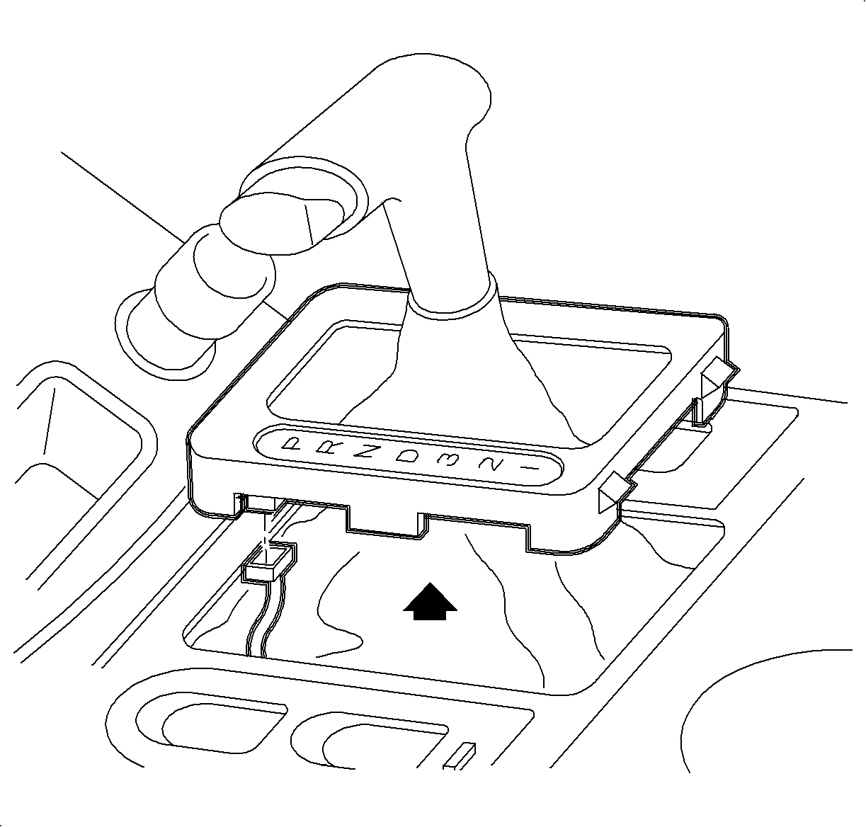
- For vehicles equipped with automatic transaxle only - Pull up on the PRNDL cover to disengage the cover.
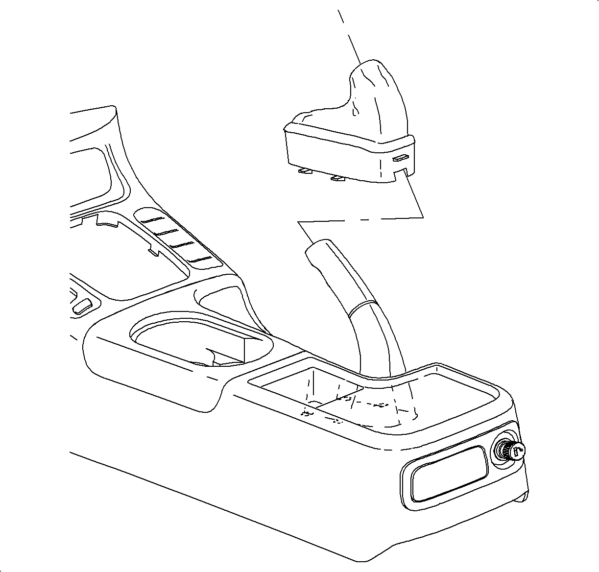
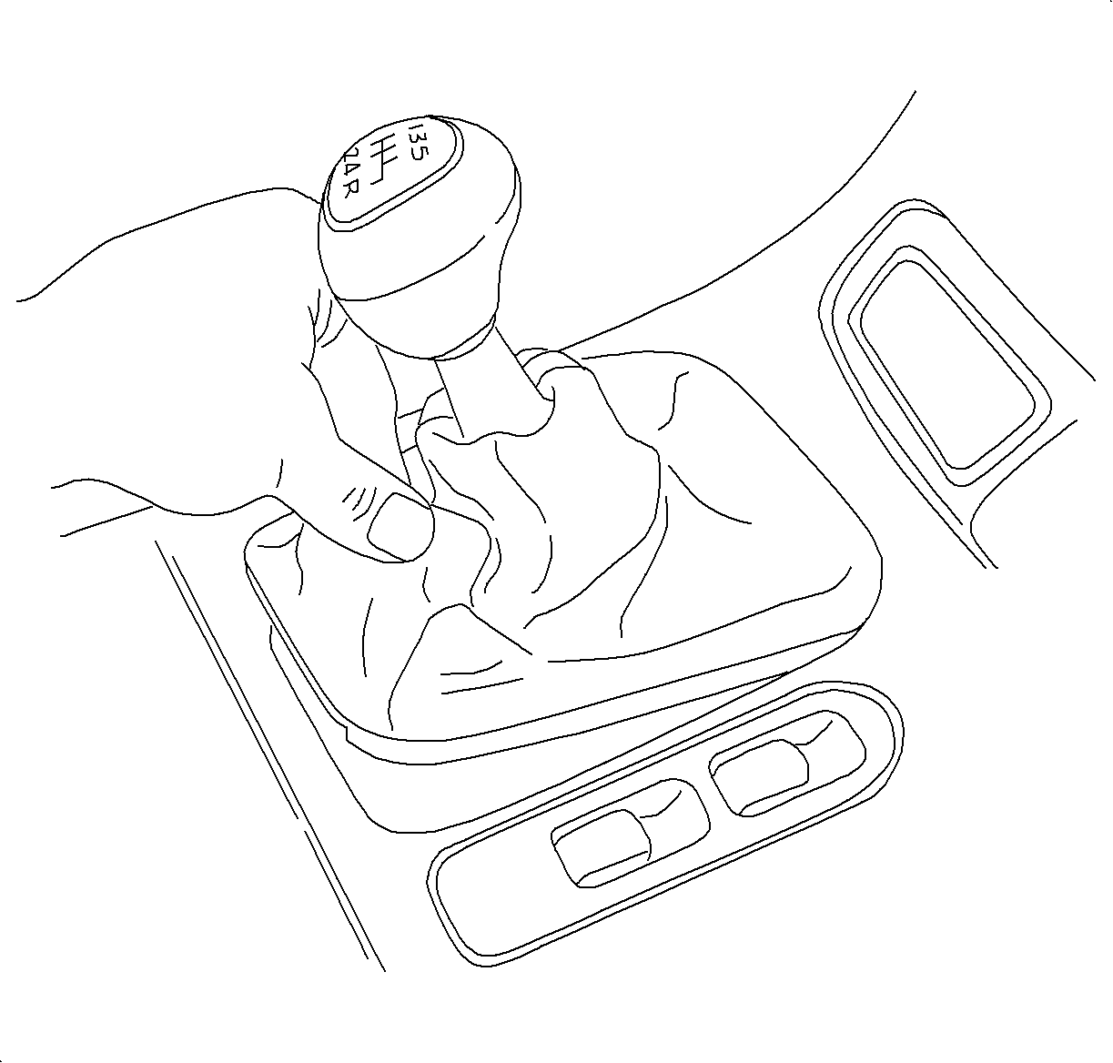
- For vehicles equipped with a 5-speed transaxle only - Pull up on the shifter boot to disengage the boot.
- Move the front seats to the forward most position and remove the console rear fasteners.
- Move the front seats to the rearward most position and remove the console front fasteners.
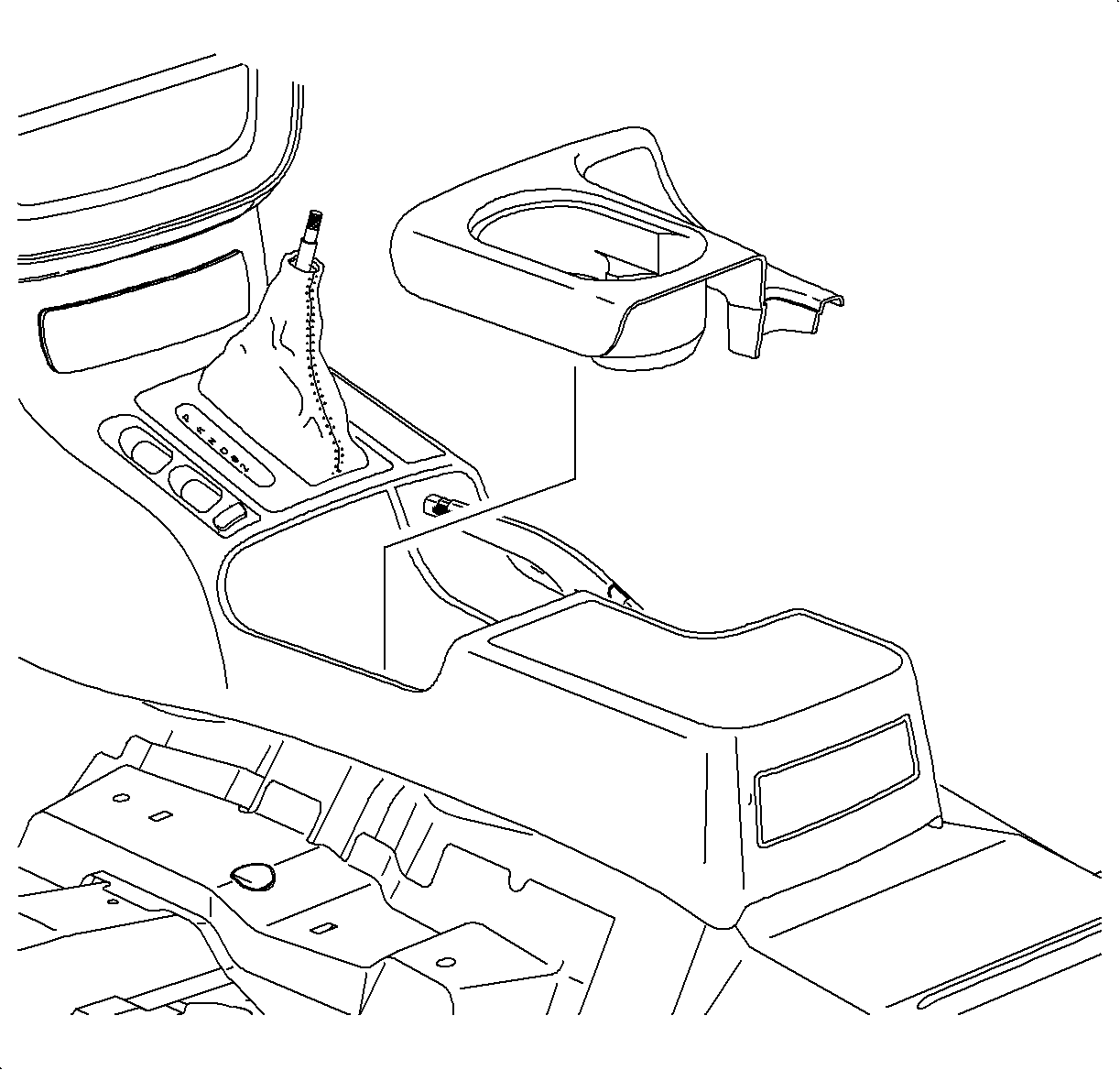
- Gently lift the console up and over the shifter (or PRNDL cover) and remove the console assembly.
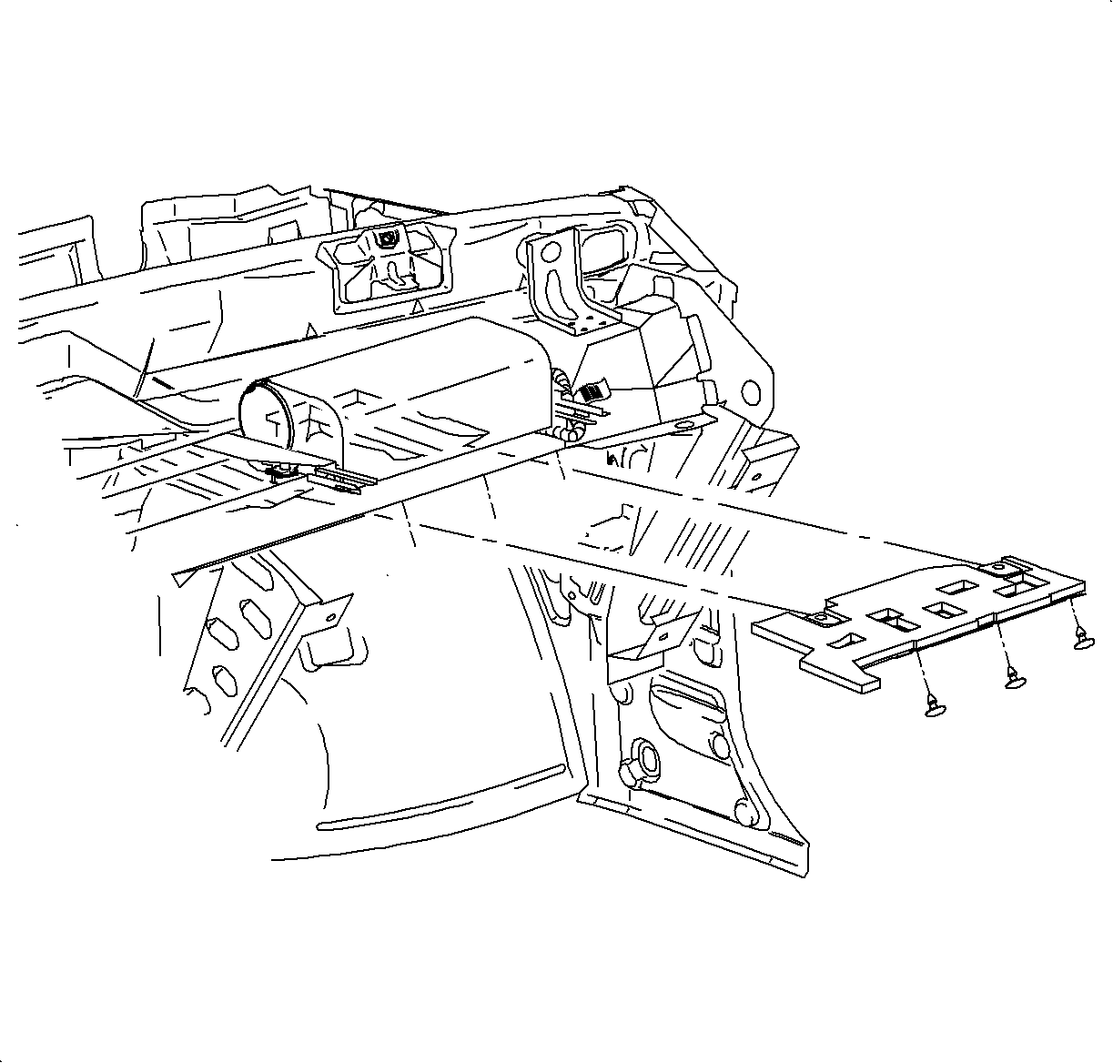
- Remove the I/P bracket.
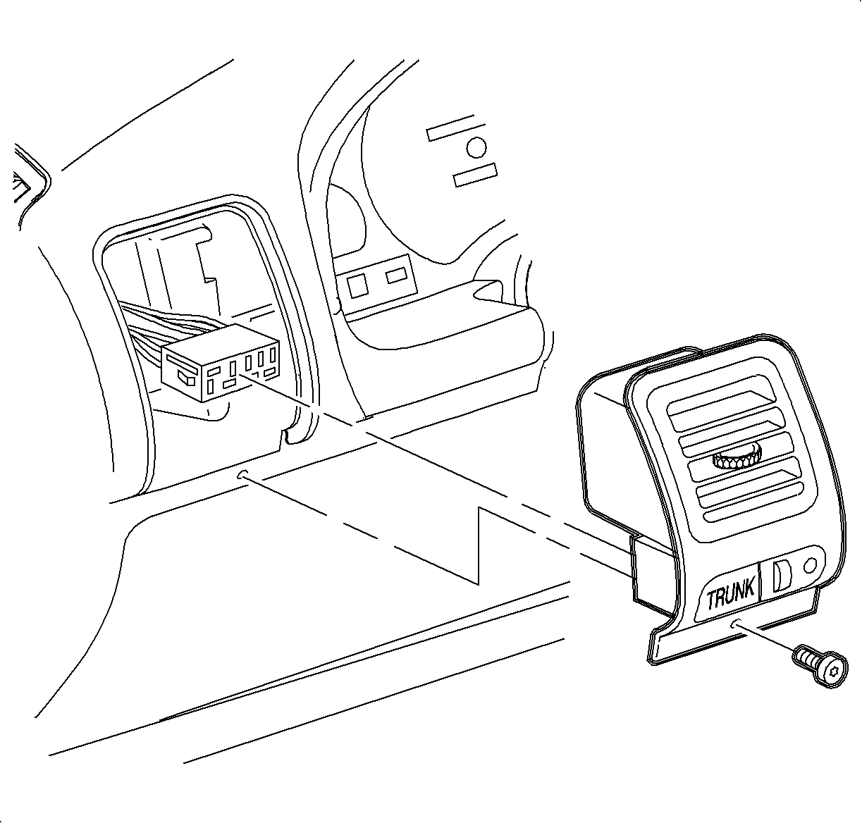
- Remove the center trim plate by grabbing the trim plate at the A/C vent area and gently pulling to disengage the attaching clips.
- Tilt the trim plate sideways and disconnect the trim plate switch harnesses. Then remove the trim plate.
- Remove the radio fasteners and partially remove the radio to expose the radio electrical connections.
- Disconnect the radio electrical connections and the ground strap from the radio. Then remove the radio.
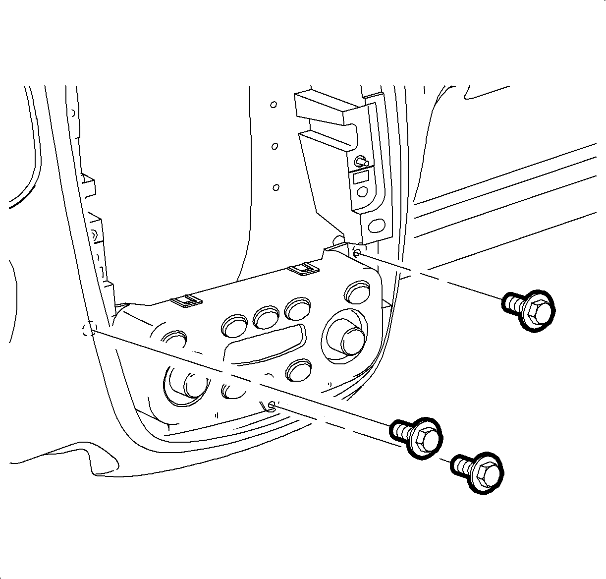
- Remove the control head-to-I/P screws.
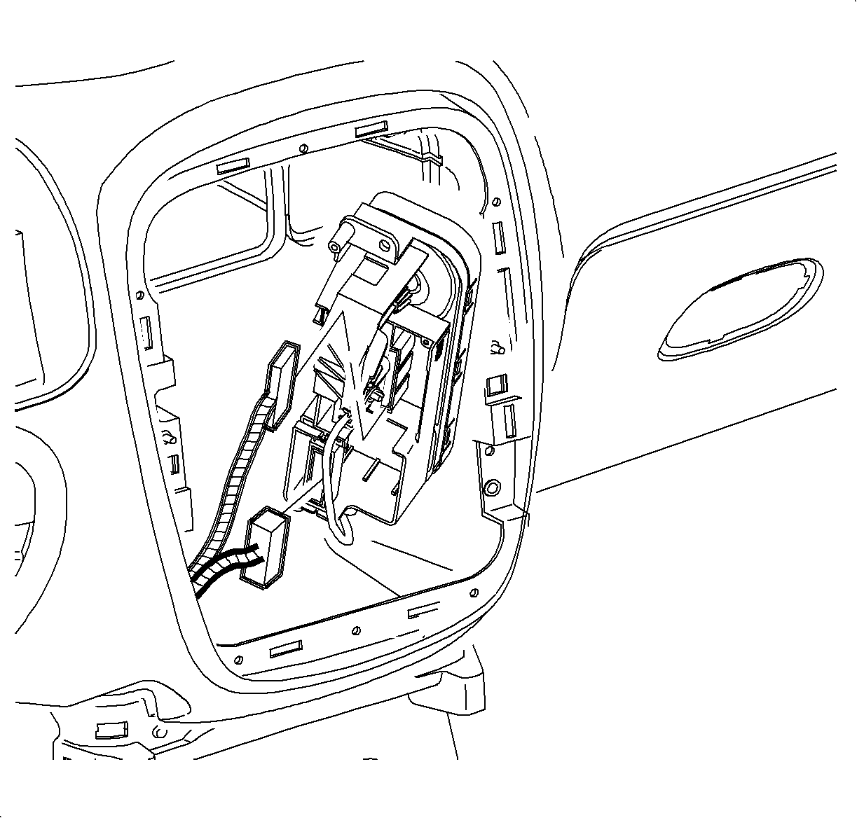
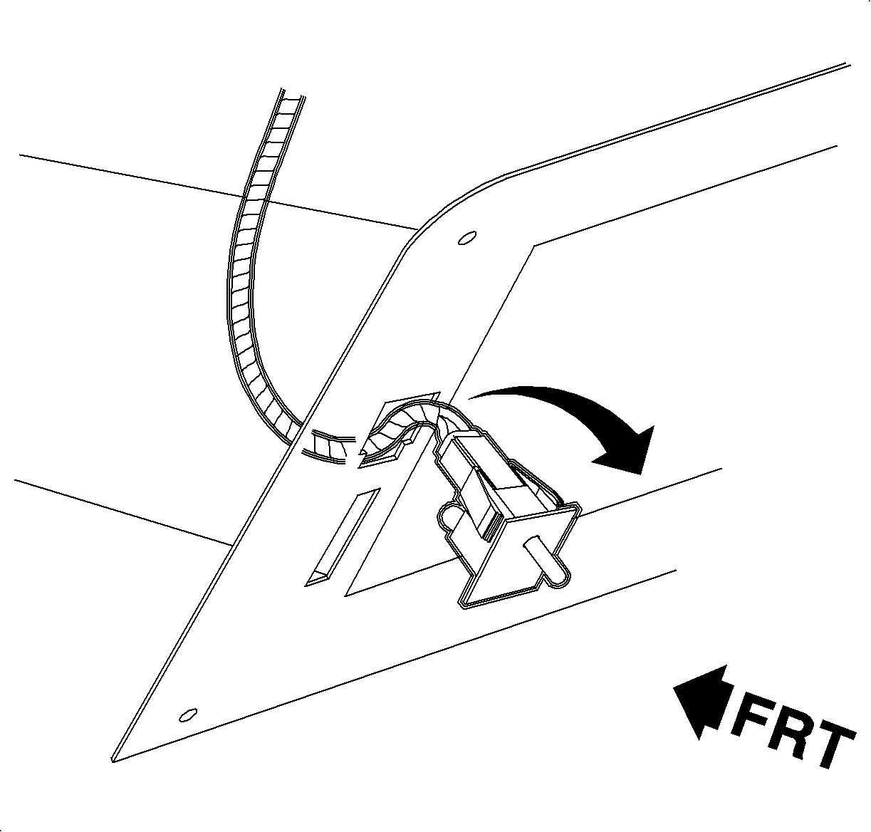
- Rotate the front of the control head upward and toward the front of the vehicle to gain access to the bottom of the control head.
- Remove the electrical connectors from the control head.
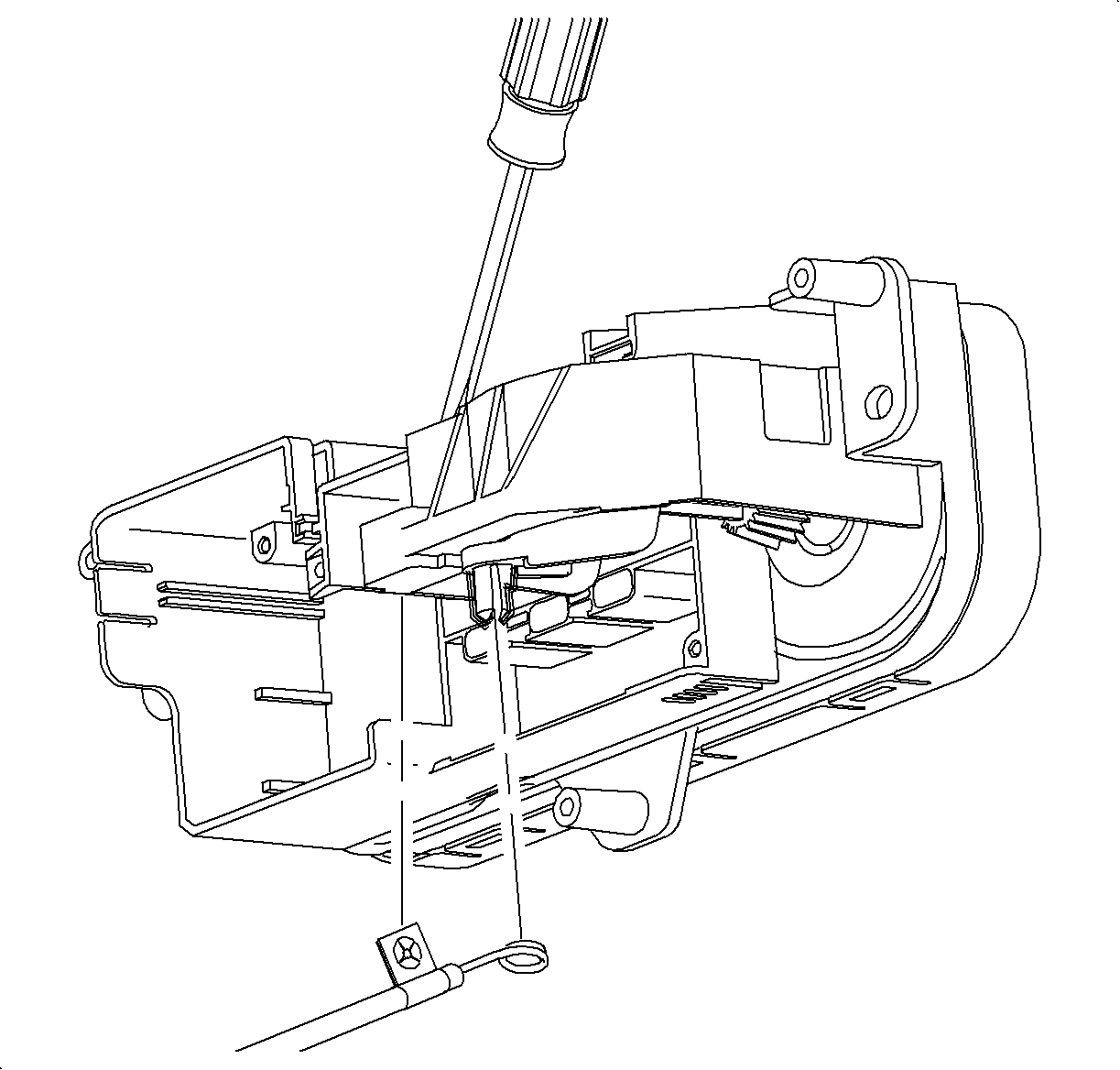
- For vehicles equipped with standard HVAC only - Rotate the control head downward and release the temperature cable flag by pushing the tab forward and pushing down on the cable at the same time.
- Remove the temperature cable eyelet from the drive pin by squeezing the drive pin together.
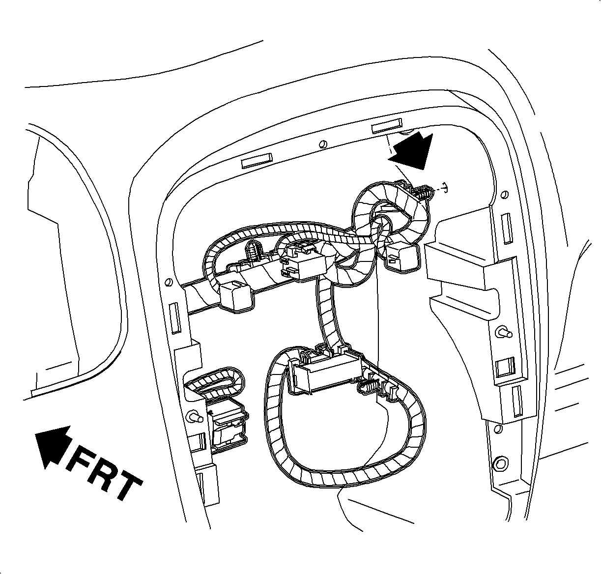
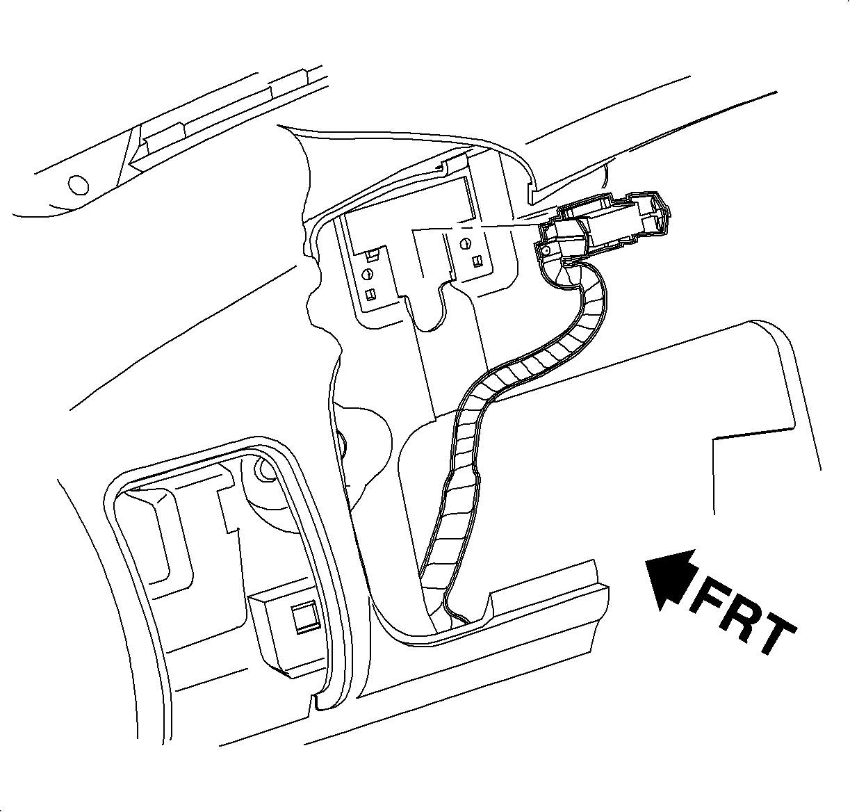
- Disconnect the wiring harness clip to I/P at the center outlet.
- Turn the steering wheel to 3 o'clock position.
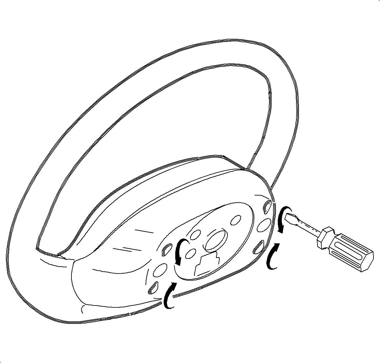
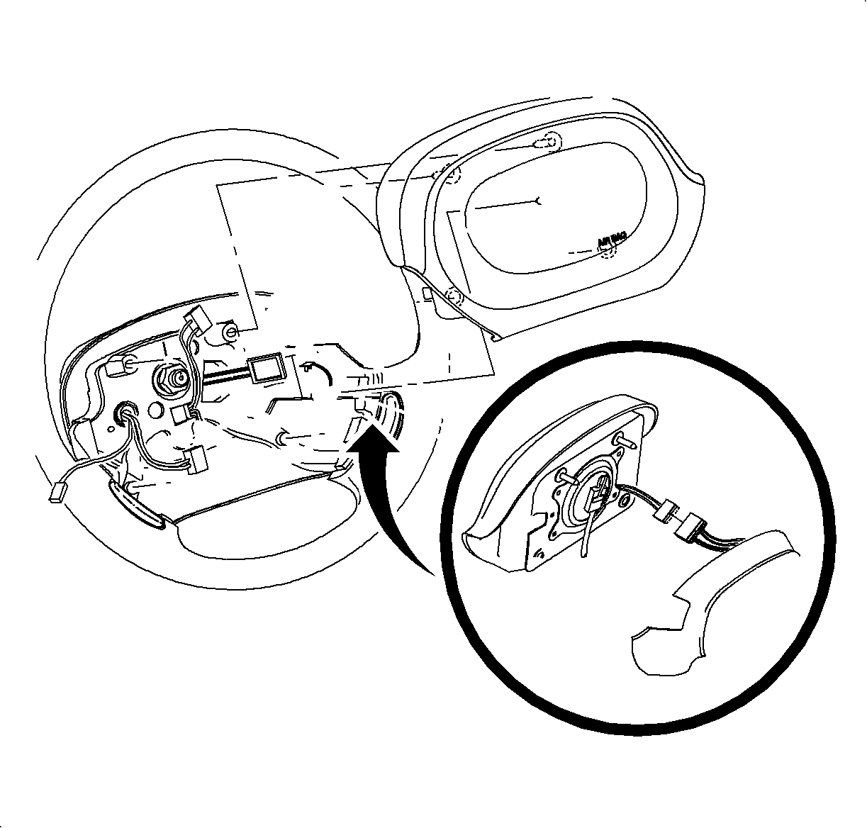
- Remove the inflator module by inserting a stubby flat-blade screw driver into the triangle shaped hole in the rear steering wheel shroud.
- Turn the screw driver to release the spring fastener, while lifting up on the corner of the bag closest to that fastener.
- Repeat for the second fastener.
- Turn the steering wheel to 9 o'clock position.
- Repeat the steps until all spring fasteners are released.
- Disconnect the inflator module harness and the horn lead.
- Remove the inflator module.
- If equipped with cruise control, disconnect the cruise control switch connection and disconnect the harness from the steering wheel.
- Remove the steering wheel attachment nut and discard the nut.
- Install J 42578 or equivalent.
- Remove the steering wheel while feeding the wiring through the steering wheel opening.
- Insert the yellow tab or use a piece of tape to prevent rotating the SIR coil.
- Remove the upper and lower steering column cover attachments.
- Remove the ignition switch bezel and remove the covers.
- Remove the wiper/washer switch and the headlamp/turn switch.
- Position the steering column to its lowest position.
- Remove the left side I/P lower dash insulator retainers and let the dash insulator hang loose.
- Remove the I/P filler by pulling at the attaching clip locations.
- Remove the 2 upper and 2 lower I/P trim plate fasteners and remove the trim plate.
- Remove the upper and lower cluster fasteners and pull rearward to remove the cluster.
- Disconnect the cluster wiring harness from the I/P.
- Remove the L/S HVAC vent housing and disconnect the electrical connections.
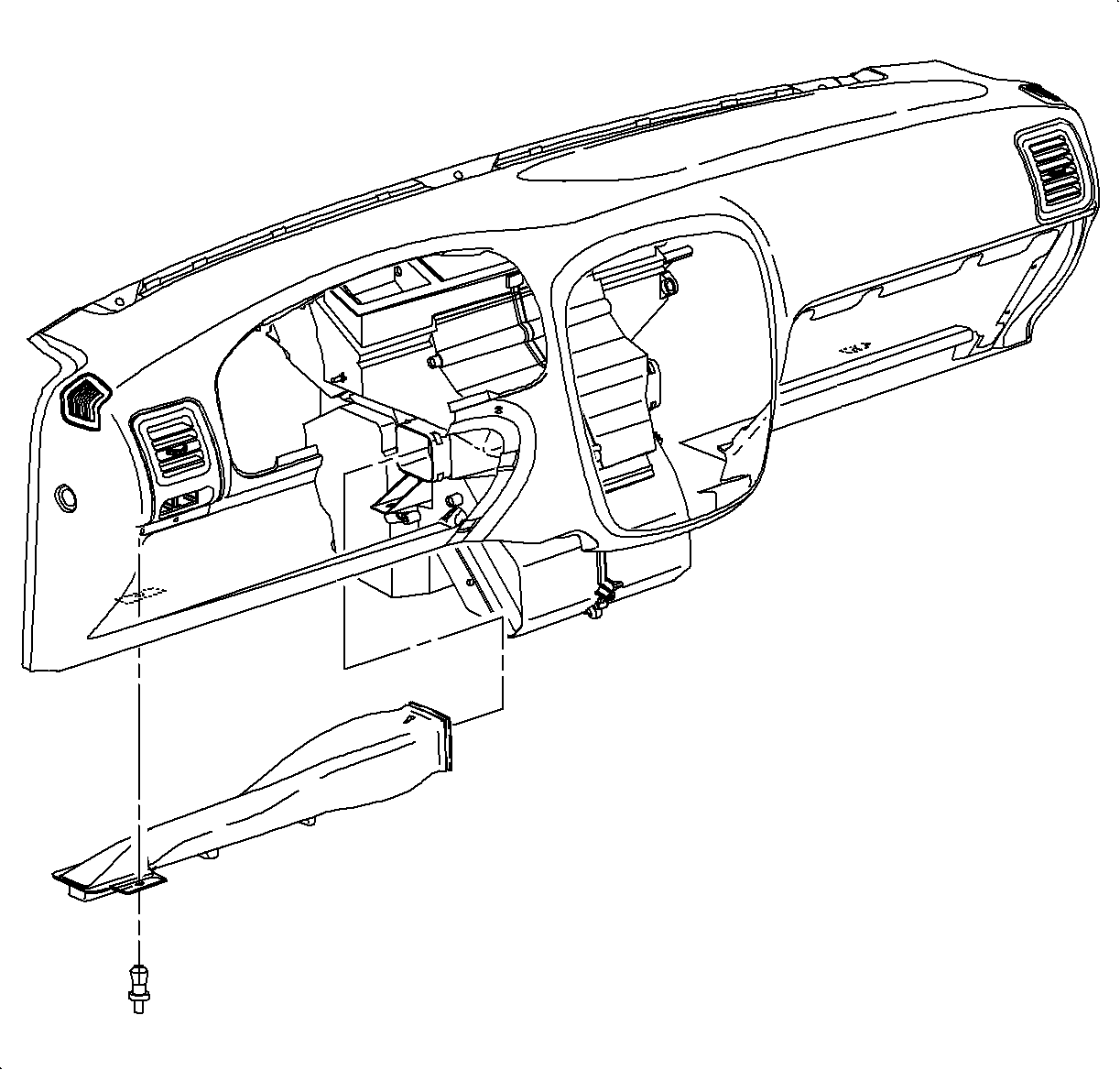
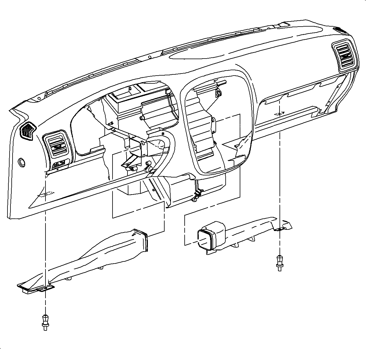
- Remove the left side lower air outlet duct.
- Open the glove compartment door.
- Remove the glove compartment lamp assembly by pulling on the lamp plunger.
- Disconnect the glove compartment lamp wiring harness from the glove compartment lamp.
- Remove the R/S I/P lower dash insulator retainers.
- Pull the insulator rearward to detach the insulator from the forward insulator retainers.
- Remove the right side heater outlet assembly retainer and remove the outlet.
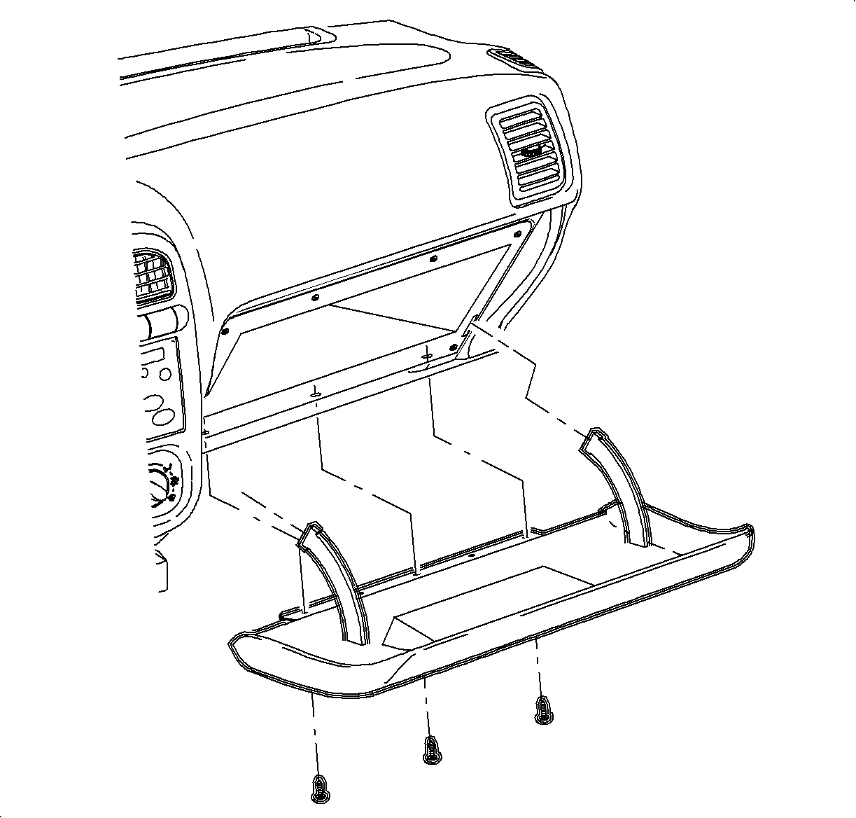
- Remove the glove compartment door.
- Remove the glove compartment bin fasteners.
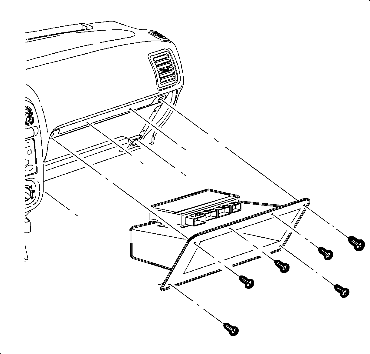
- Slowly remove the glove compartment bin tilting the bin downward to expose the body control module (BCM) module residing on top of the glove compartment bin.
- Remove the BCM module from the glove compartment by sliding the module out of the attaching slots.
- Remove the glove compartment bin.
- Let the body controller hang on the body harness.
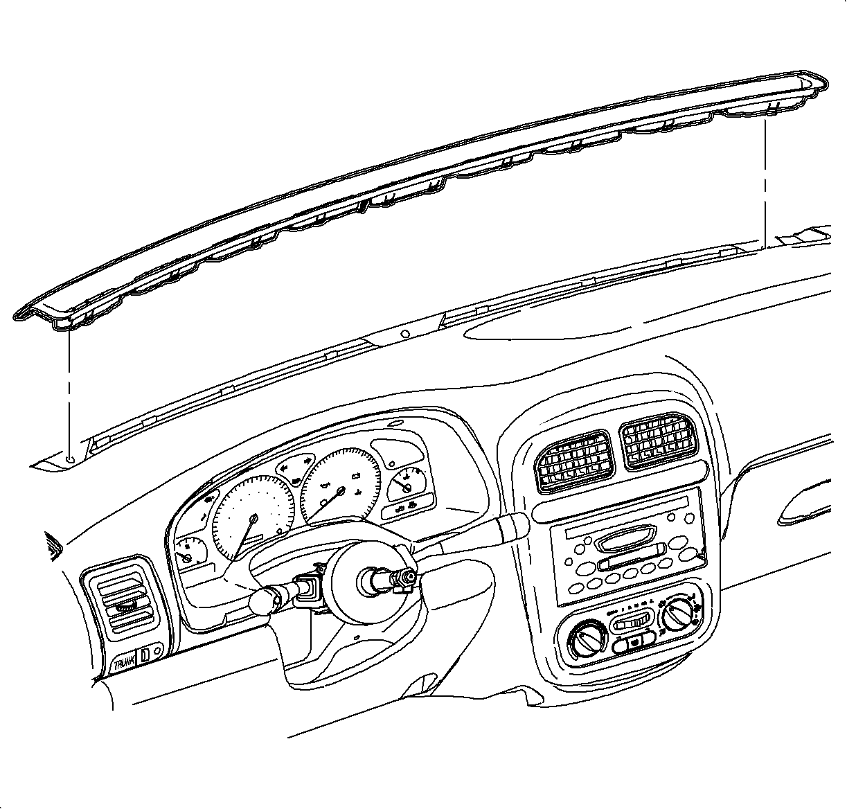
- Pull upward at the vent locations and remove the windshield defroster grille.
- Unsnap the hood release handle from the I/P by using a small screwdriver to disengage the retainer clips on both sides.
- Remove the diagnostic connection by pulling downward at the connector location.
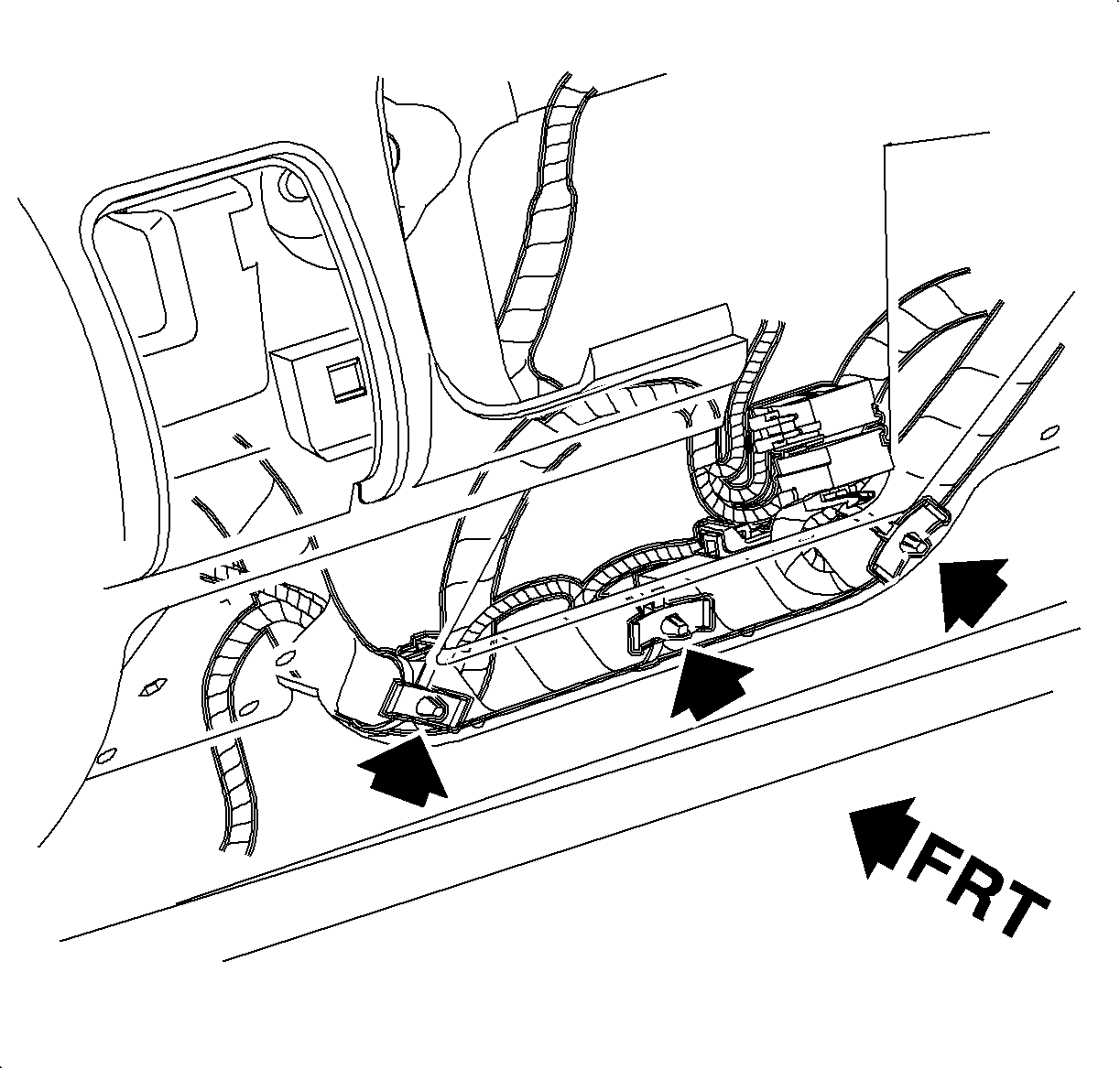
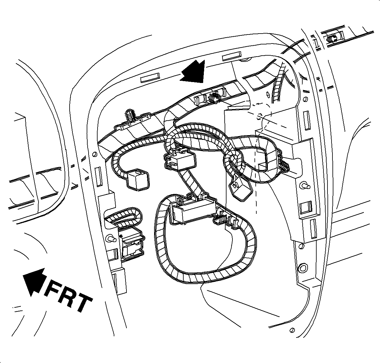
- Remove the I/P harness clips to I/P at the lower steering column location.
- Remove the I/P harness clip to I/P behind the glove compartment opening location.
- Remove the fastener at the left side I/P to beam location.
- Remove the 2 fasteners behind the cluster location.
- For vehicles equipped with advanced audio system only - Remove the fasteners that attach the amplifier to the I/P beam.
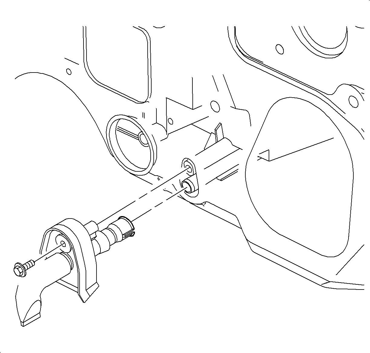
- Slide the amplifier off of m the clutch pedal bracket.
- Disconnect the amplifier wire harness connectors from the amplifier.
- Remove the amplifier from the vehicle.
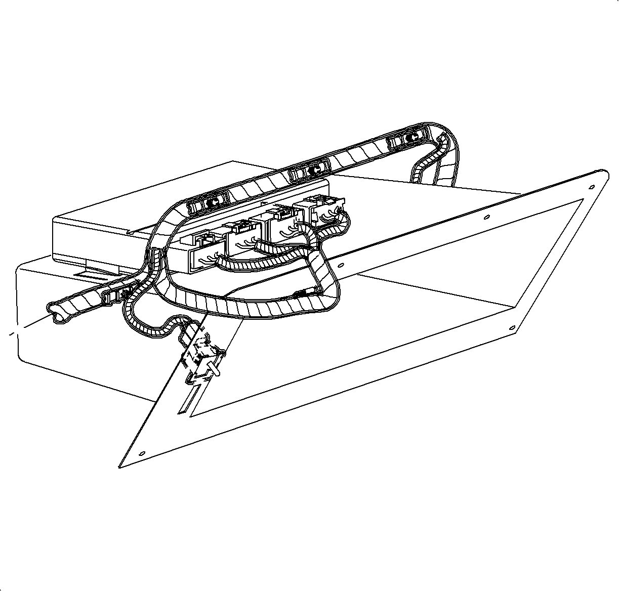
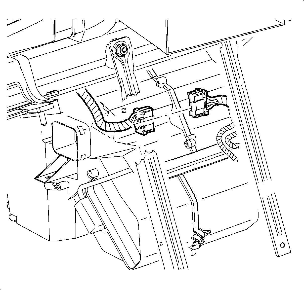
- Disconnect the I/P harness electrical connector from the module harness.
- Remove the upper intermediate shaft bolt and disconnect the shaft from the steering column.
- Remove the steering column lower support bolt.
- Remove the steering column upper support bolt and nut.
- Remove the steering column from the vehicle.
- Open the drivers side door completely and install a protective covering on the door inner hinge area to prevent damage to paint.
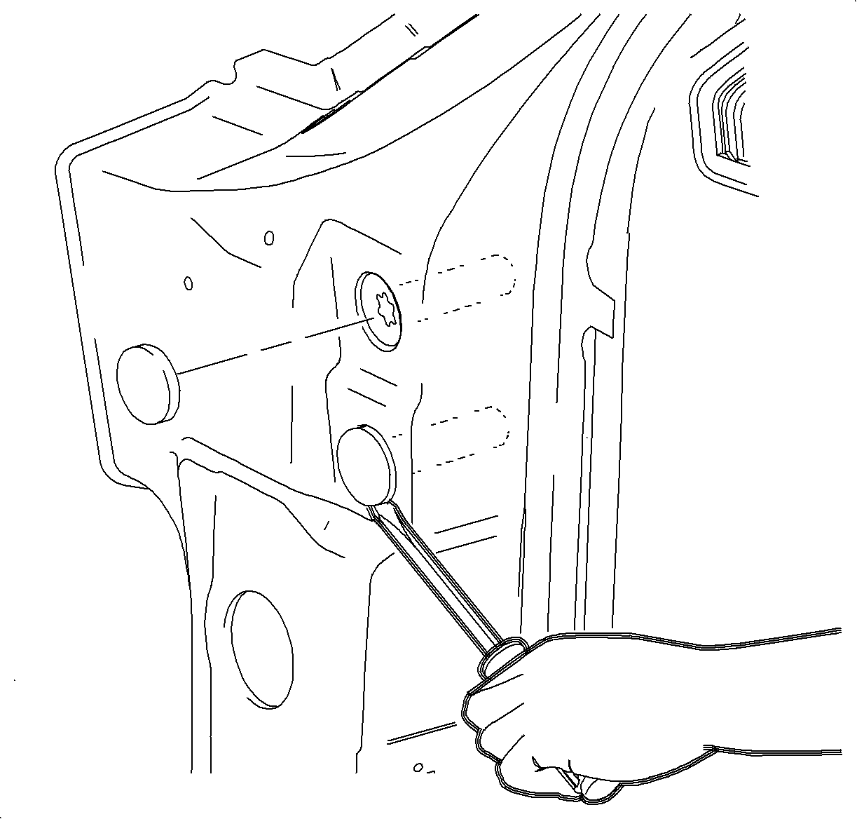
- Using a flat-blade screwdriver, remove the black plastic beam bolt covers.
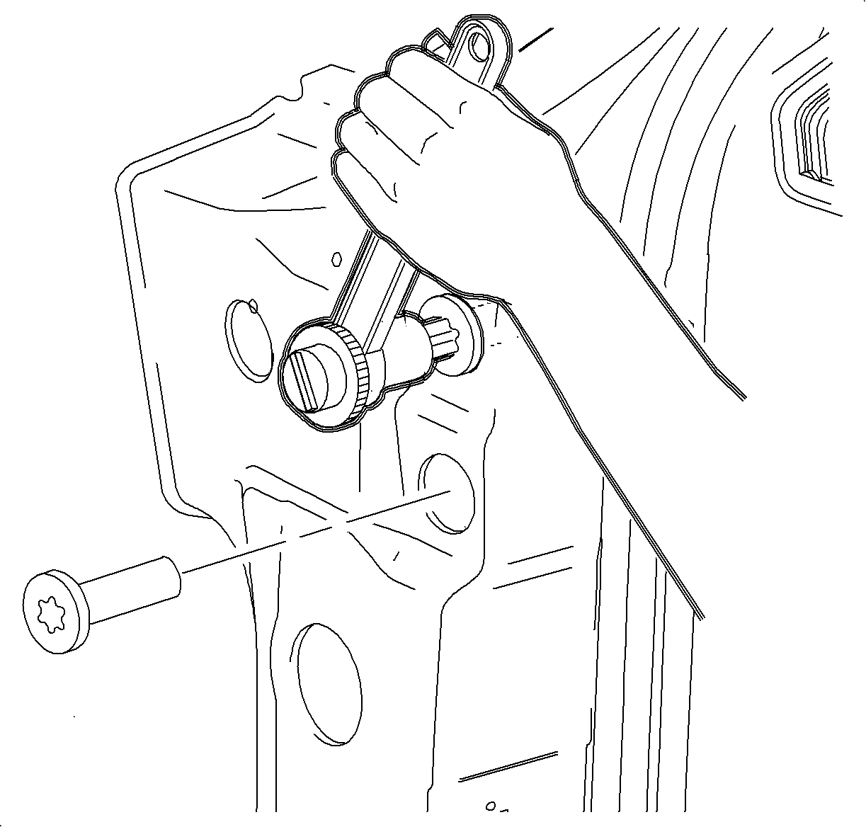
- Using a T30 TORX® socket, remove both outer beam bolts. Use caution not to damage the door paint.
- Install the J 43894 into A-pillar beam bolt holes. The tool flange should fit tight to the A-pillar surface when completely installed. This tool is needed to prevent accidentally dropping a bolt inside the A-pillar.
- Using a T40 TORX® socket, remove both inner beam bolts.
- Repeat the beam bolt removal procedure on passenger's side.
- Remove the J 43894 .
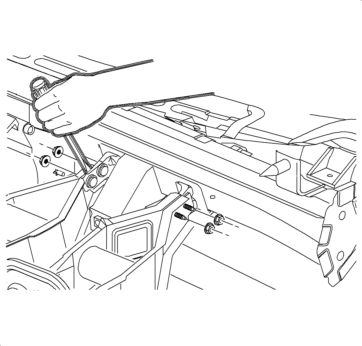
- Remove the I/P beam to steering column brace nuts.
- Using a large screwdriver, pry the steering column braces apart to clear the beam studs and remove the beam from the vehicle.
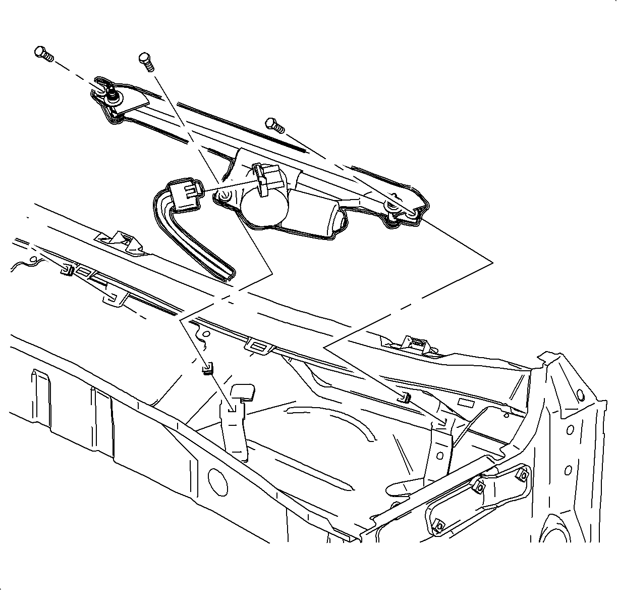
- With the engine hood open, remove the wiper arm assemblies.
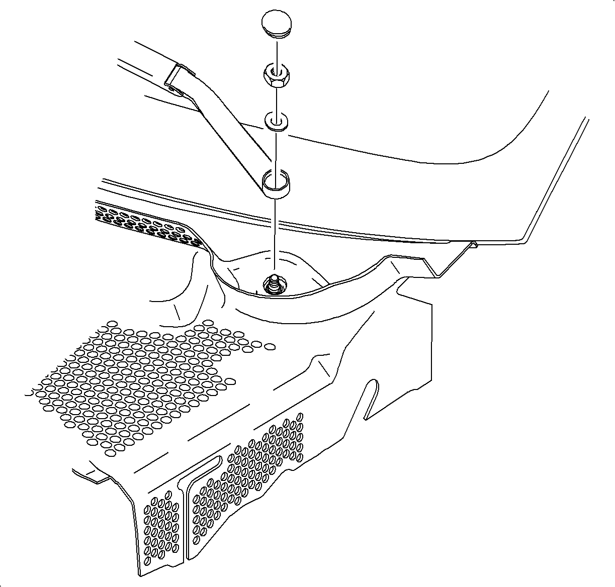
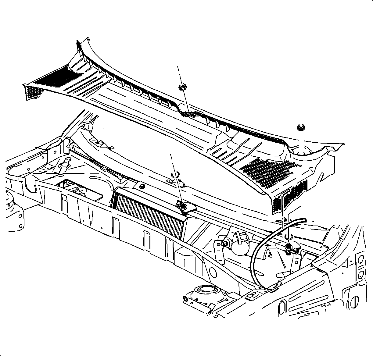
- Remove the cowl retaining nuts and remove the cowl screen assembly.
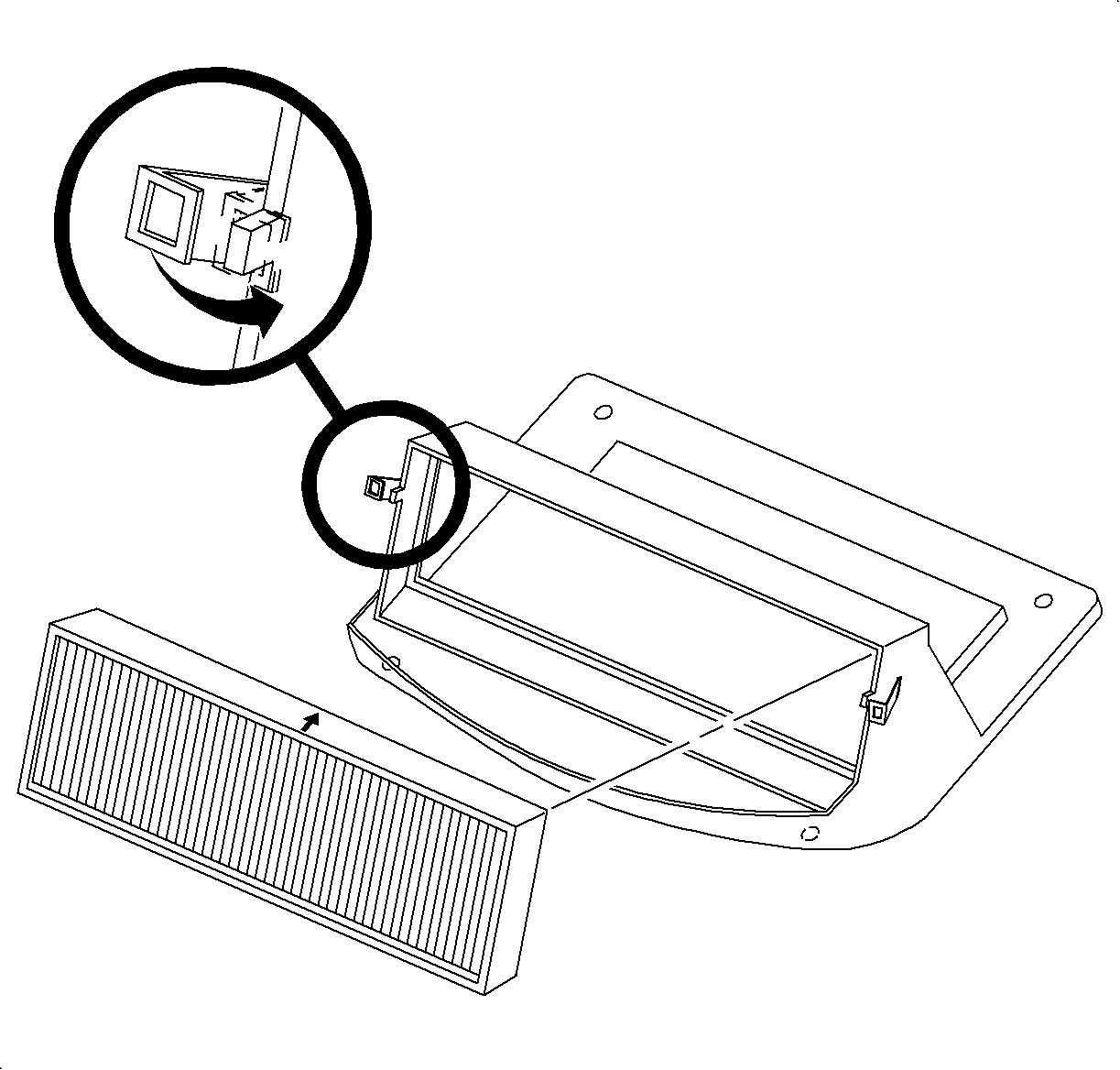
- Rotate the locking tabs outward to release the filter assembly.
- Remove the filter by lifting straight up.
- Remove the wiper module retaining bolts and slide the wiper module to the right.
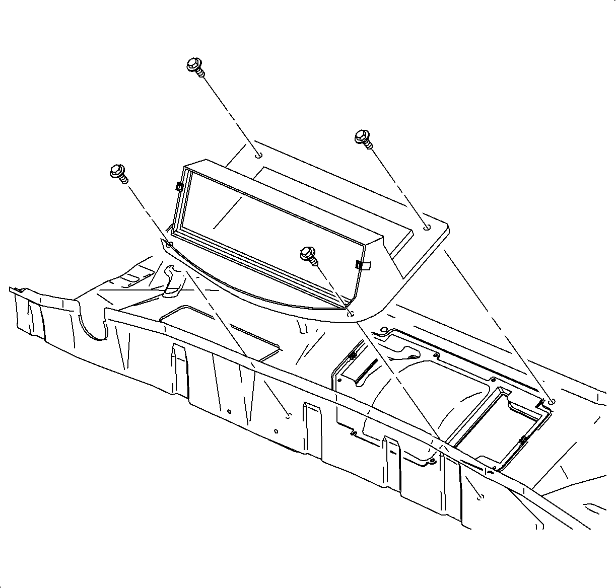
- Remove the filter housing attachment bolts and remove the filter housing.
- Remove the evaporator condensate drain tube screw and remove the drain tube.
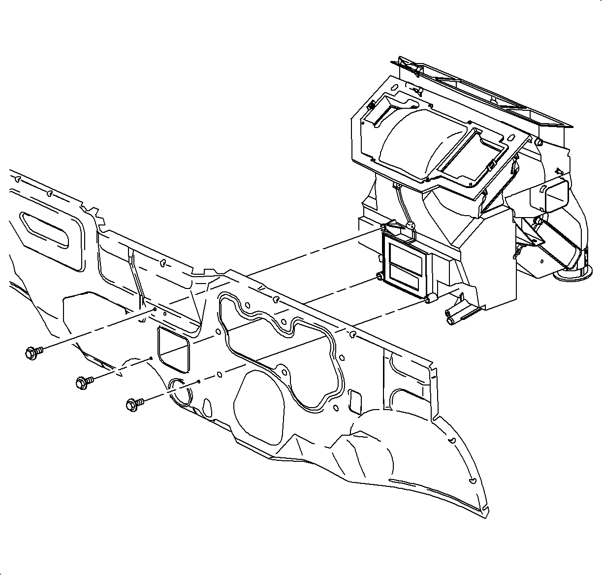
- Remove the HVAC module-to-front of dash bolts.
- Remove the HVAC module from the vehicle.
Important: Verifying the purity of the refrigerant with a purity identifier before recovery is recommended.
Caution: Refer to HVAC Compressor Lines/Hoses Caution in the Preface section.
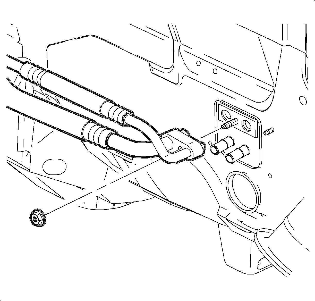
Important: When removing the TXV, keep dirt and foreign material from getting on or into the O-ring sealing surfaces. Clean tools and a clean work area are important for proper service. The TXV seal area should be cleaned before any repairs are performed. The parts must be kept clean at all times and any parts to be assembled should be cleaned with a non-petroleum based solvent and dried with air. Use only lint free cloths to wipe parts. Do not allow solvent to enter evaporator or hoses.
On earlier vehicles a bolt was used instead of a stud/nut.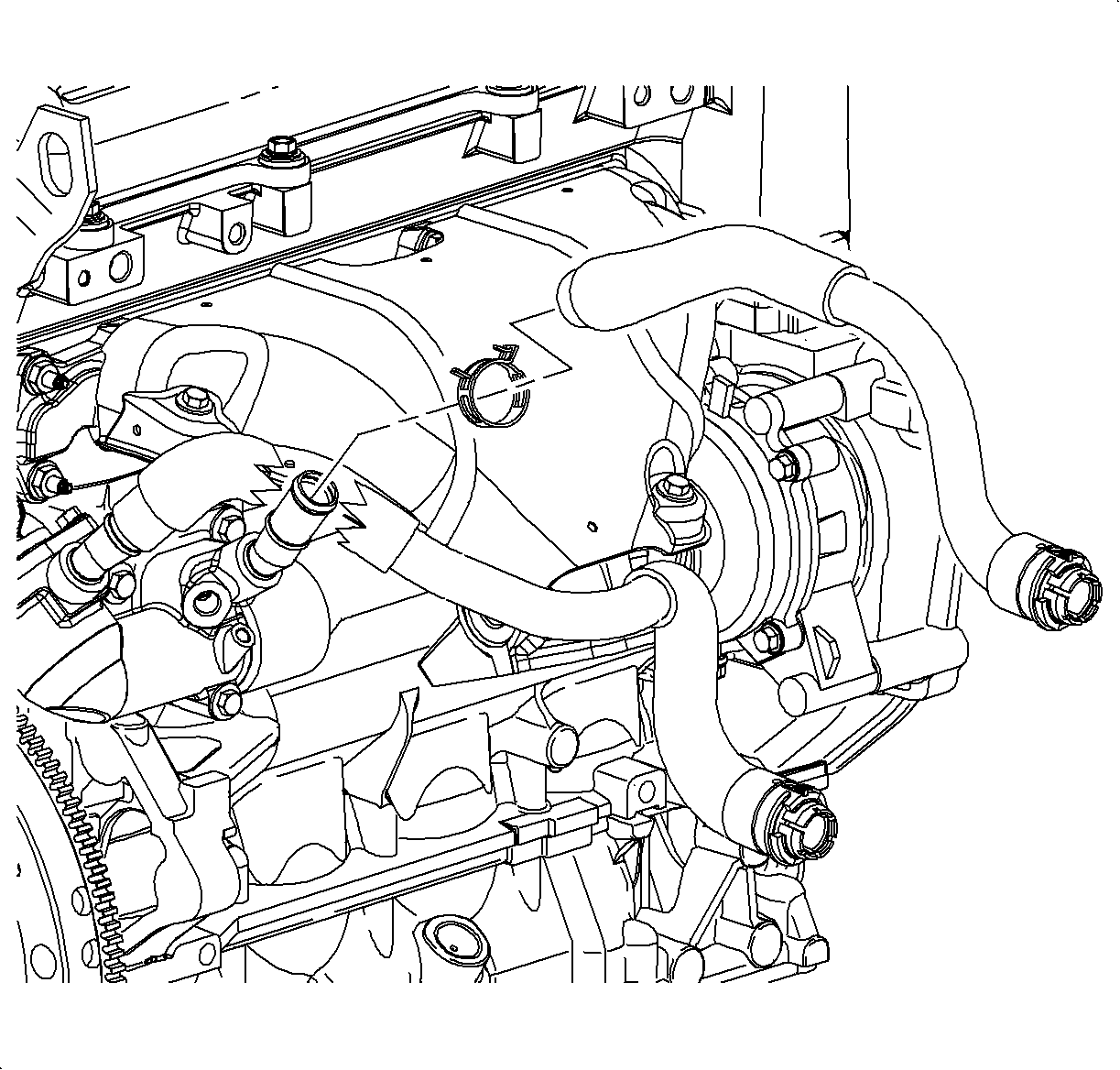
| • | From the auxiliary water pump outlet on L81 engines. |
| • | From the thermostat outlet on L61 engines. |
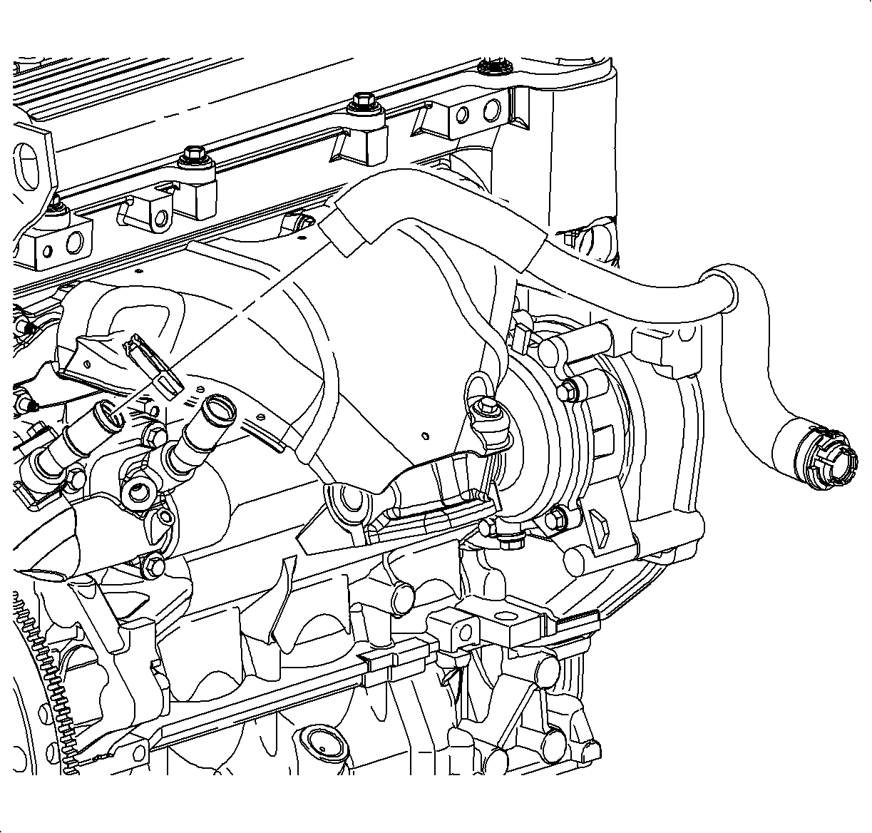
| • | From the cylinder head bridge on L81 engines. |
| • | From the block inlet on L61 engines. |
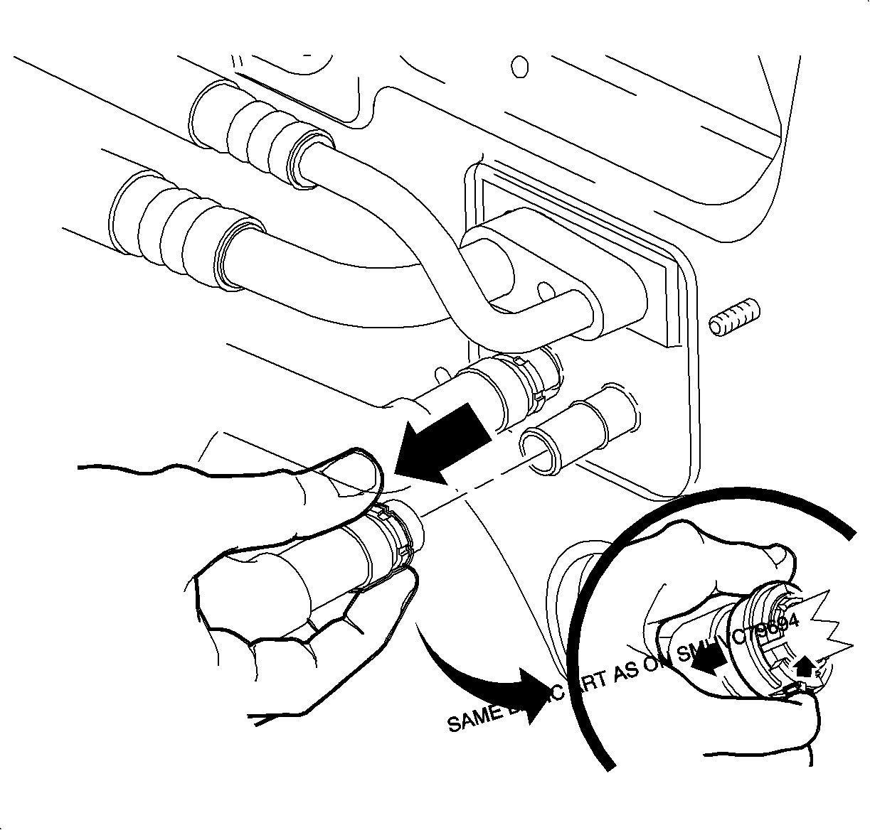
Important: Green plastic rings may be found hanging on the pipes after hose removal, these are manufacturing aids and should be discarded.
| 13.1. | Depress the quick connect collar tab located at 6 o'clock. |
| 13.2. | Pull the black collar toward the front of vehicle. |
| 13.3. | Pull the quick connect off the heater core pipe. |
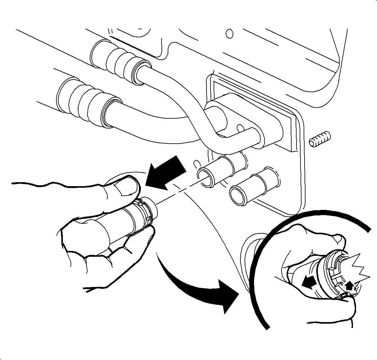
| 14.1. | Depress the quick connect collar tab located at 6 o'clock. |
| 14.2. | Pull the black collar toward the front of vehicle. |
| 14.3. | Pull the quick connect off the heater core pipe. |
| 14.4. | Disable the SIR System. Refer to Disabling the SIR System in SIR. |
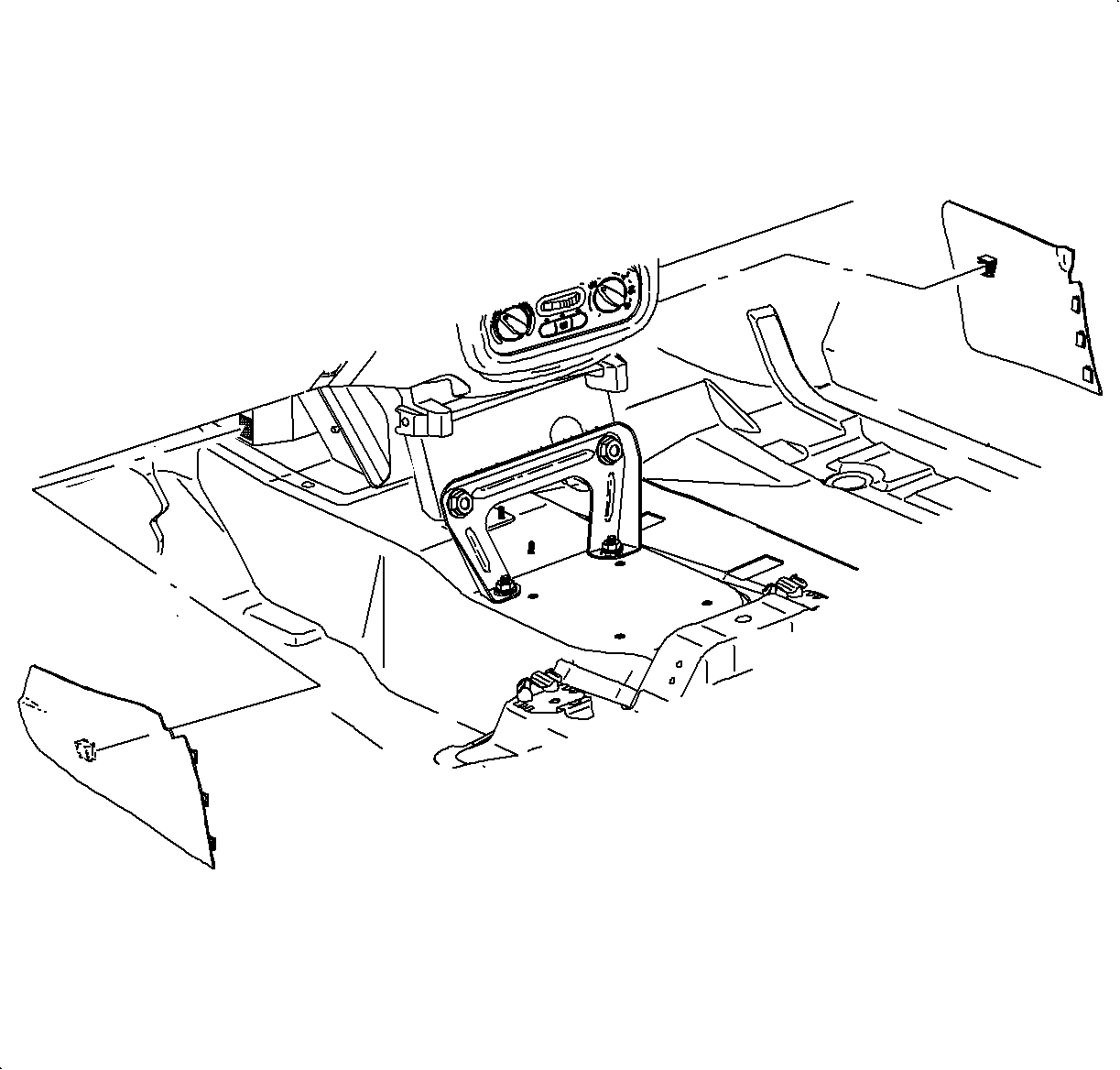
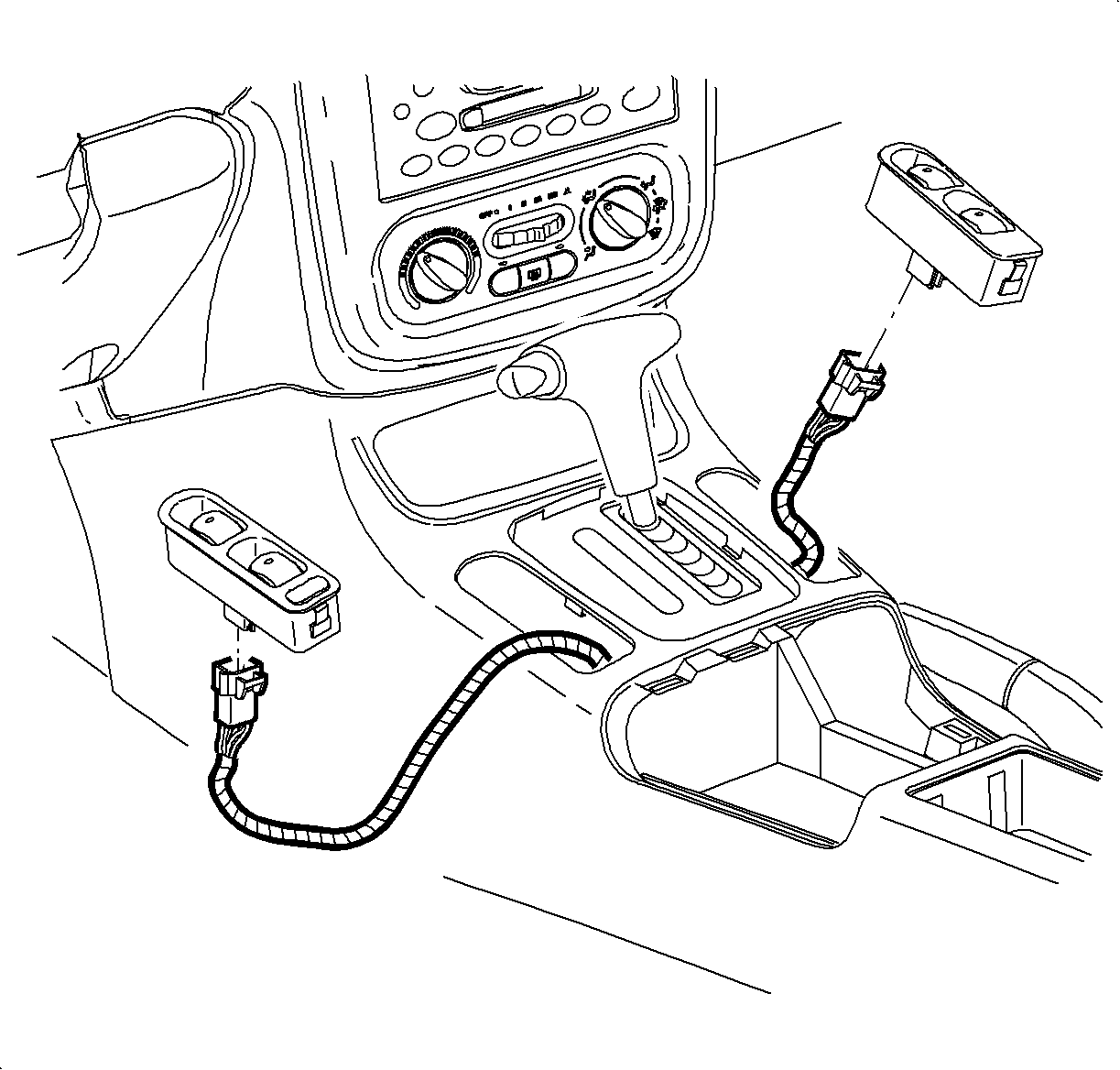
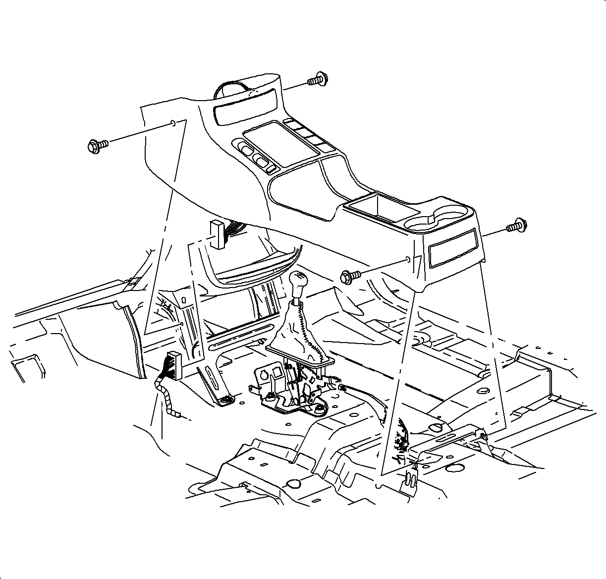
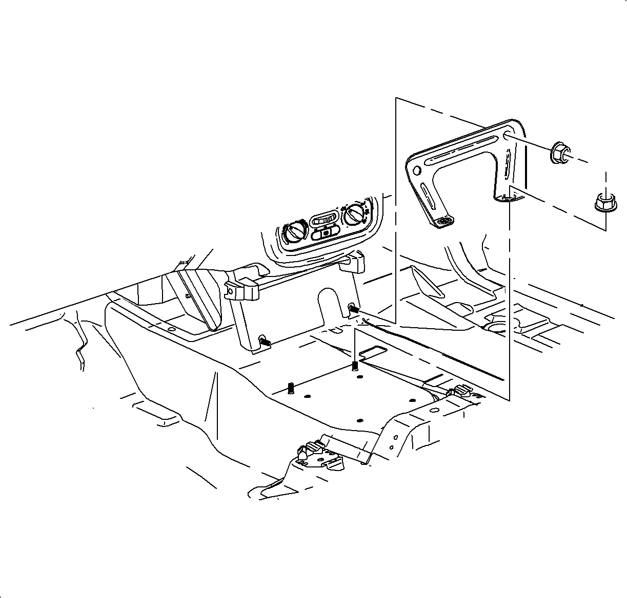
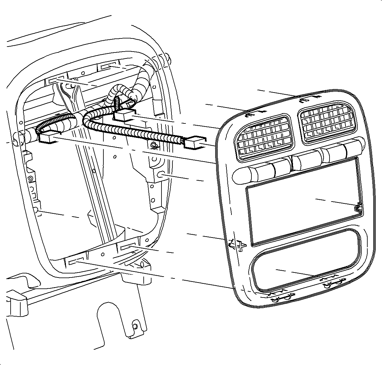
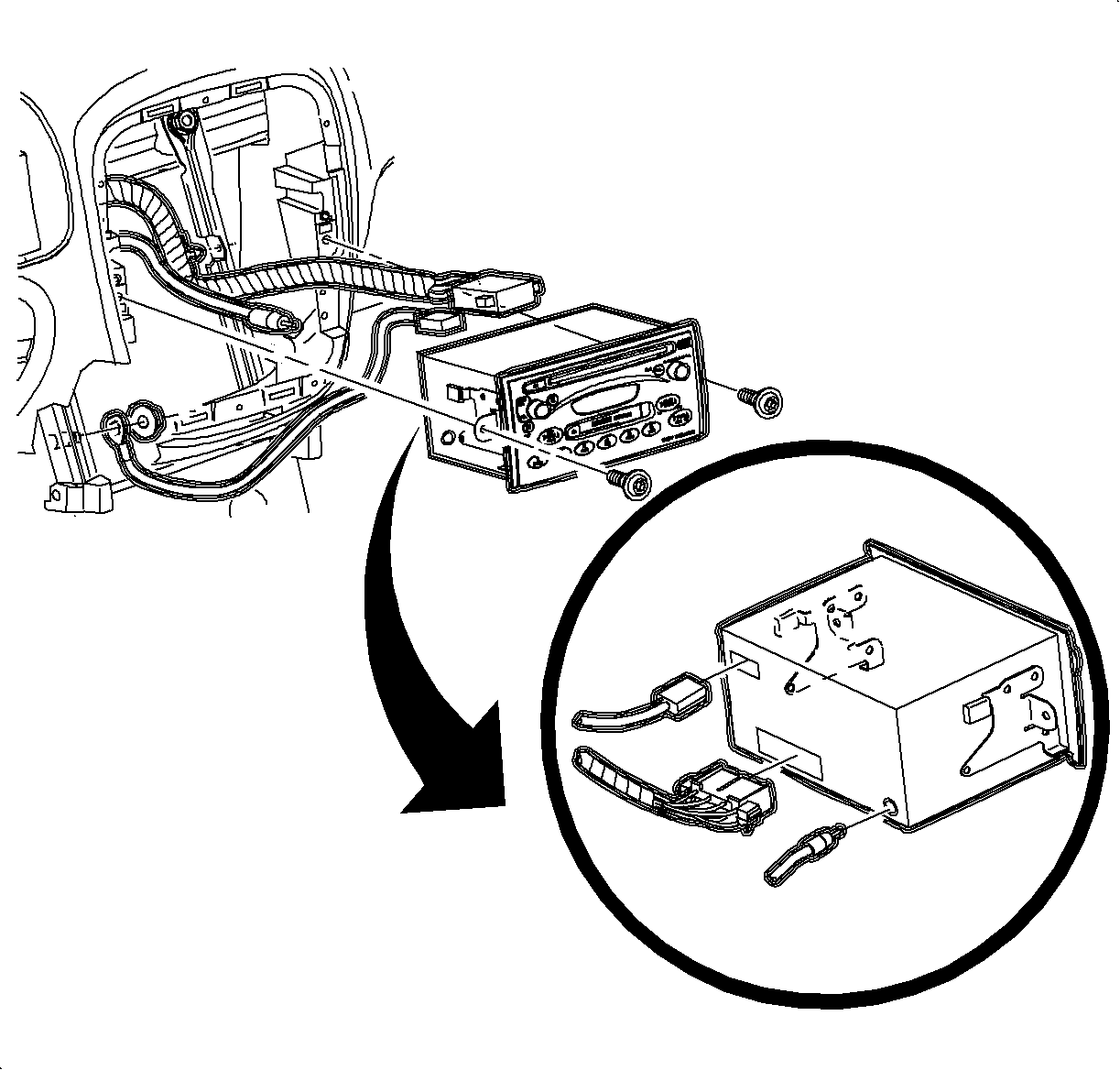
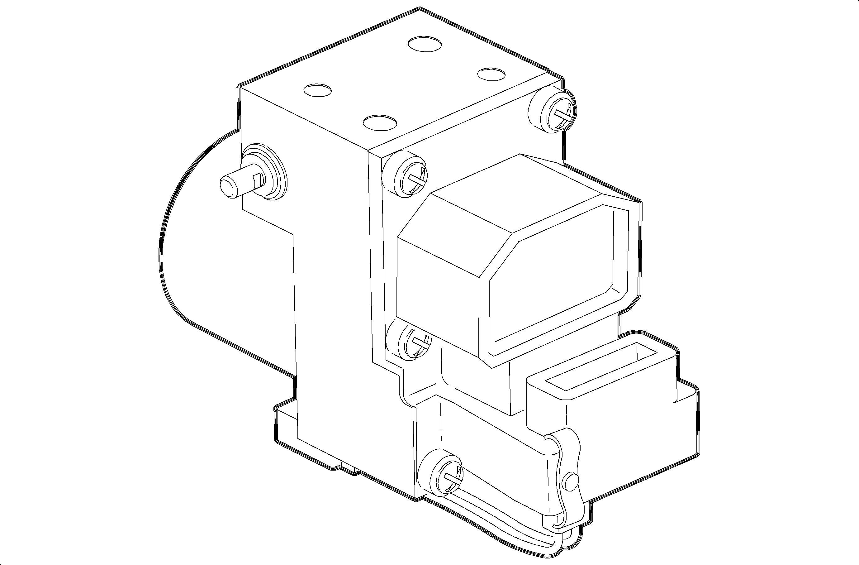
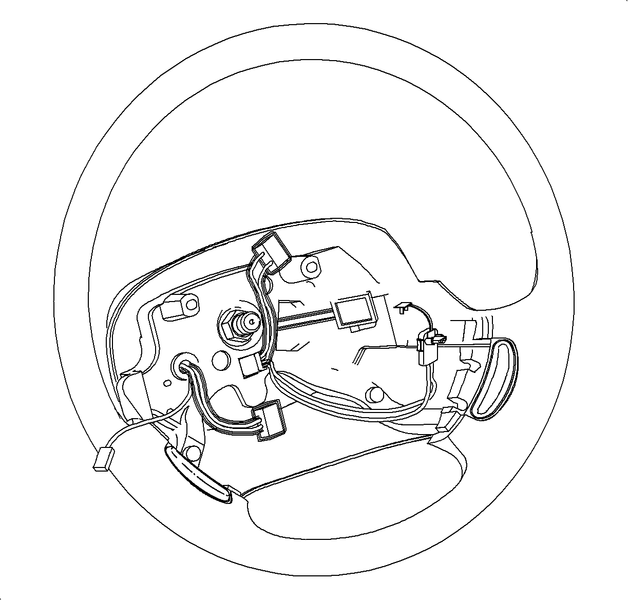
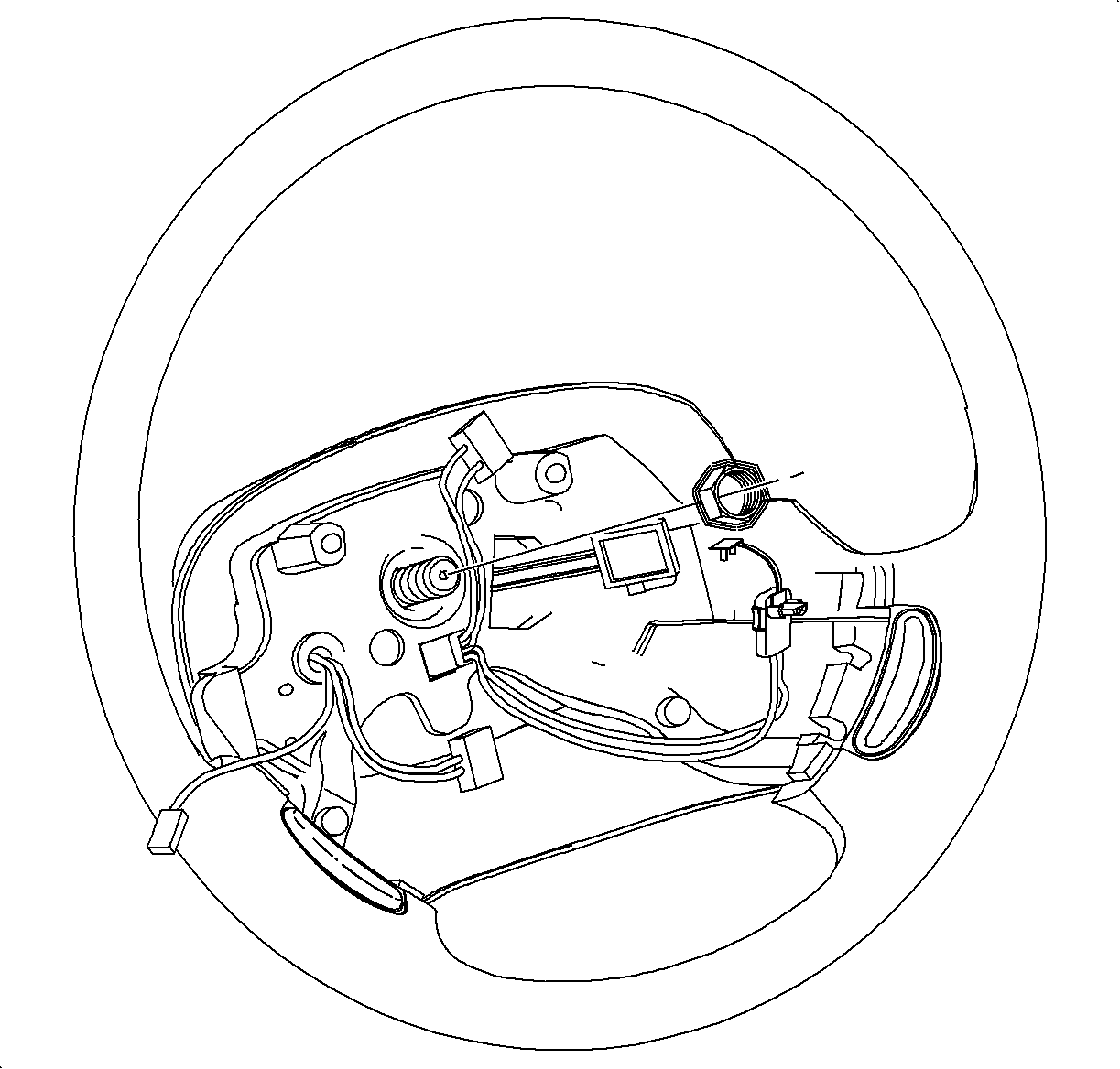
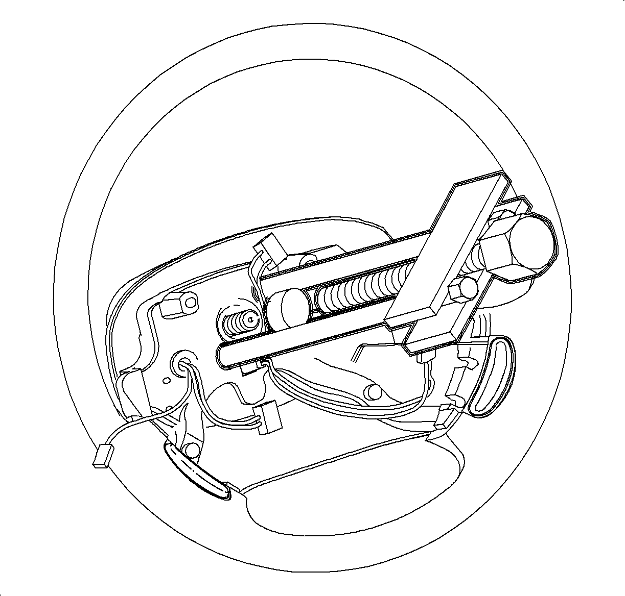
Important: Always align the front wheels to the straight-ahead position when installing or removing a roll connector.
If the yellow tab is not available, use tape to prevent the SIR coil from rotating.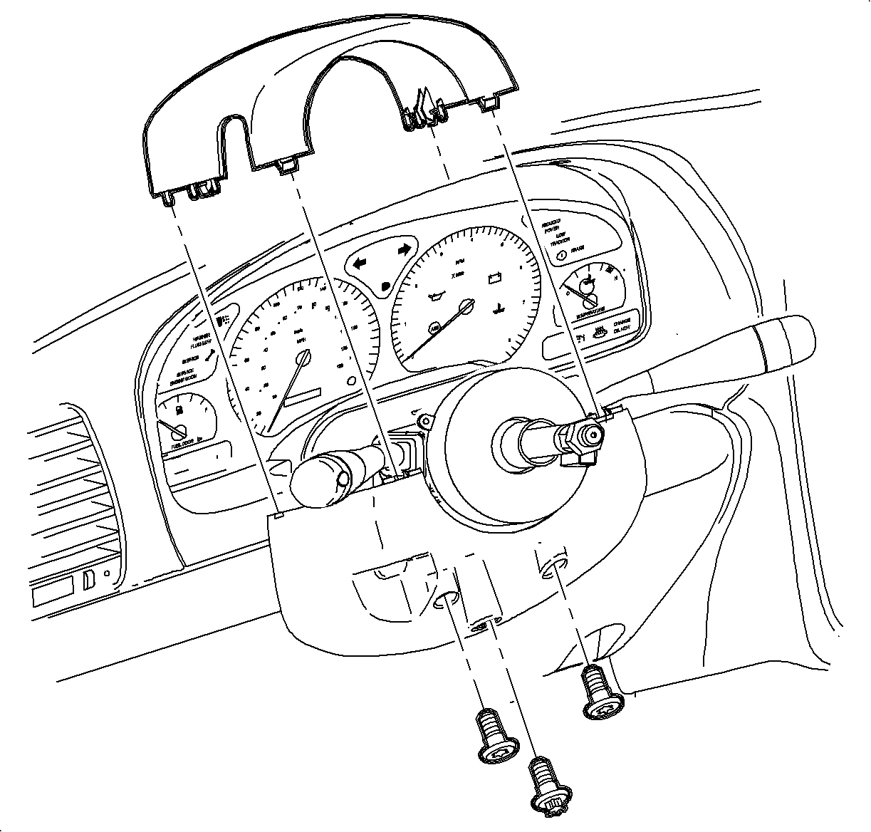
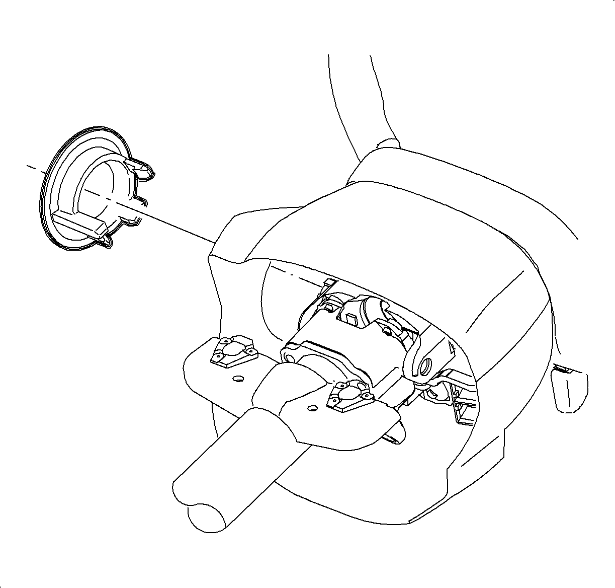
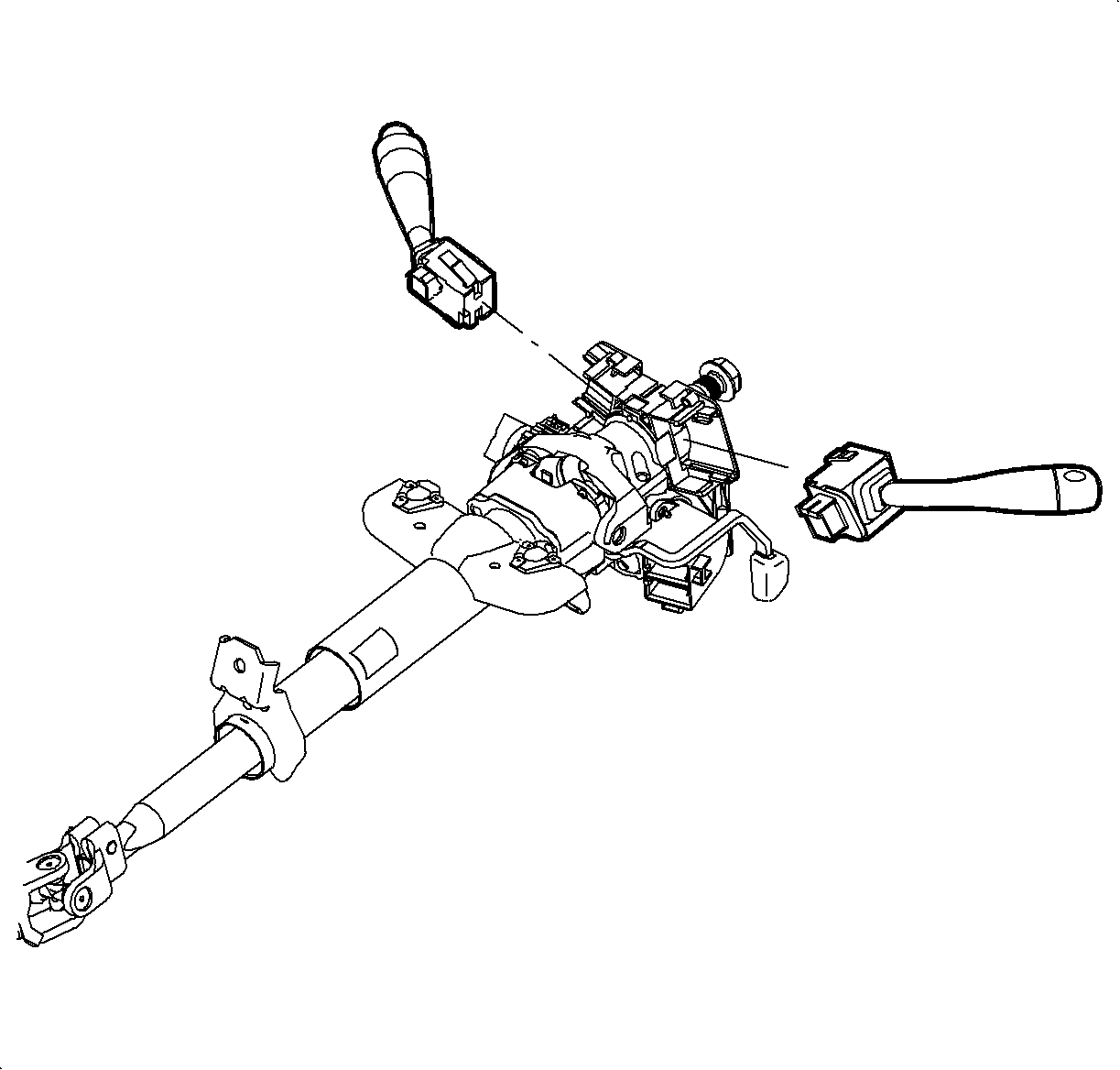
Important: Cover top of steering column.
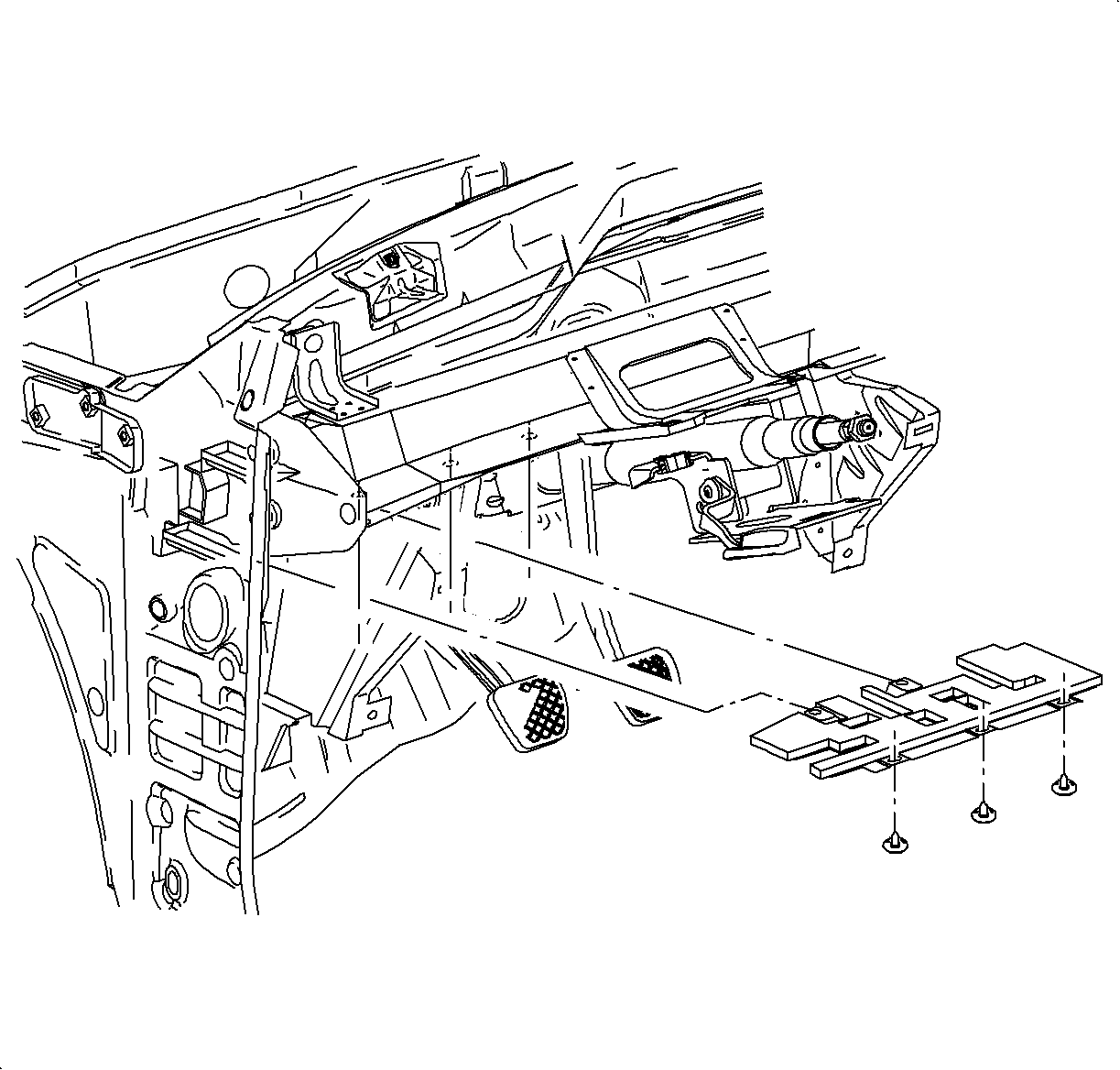
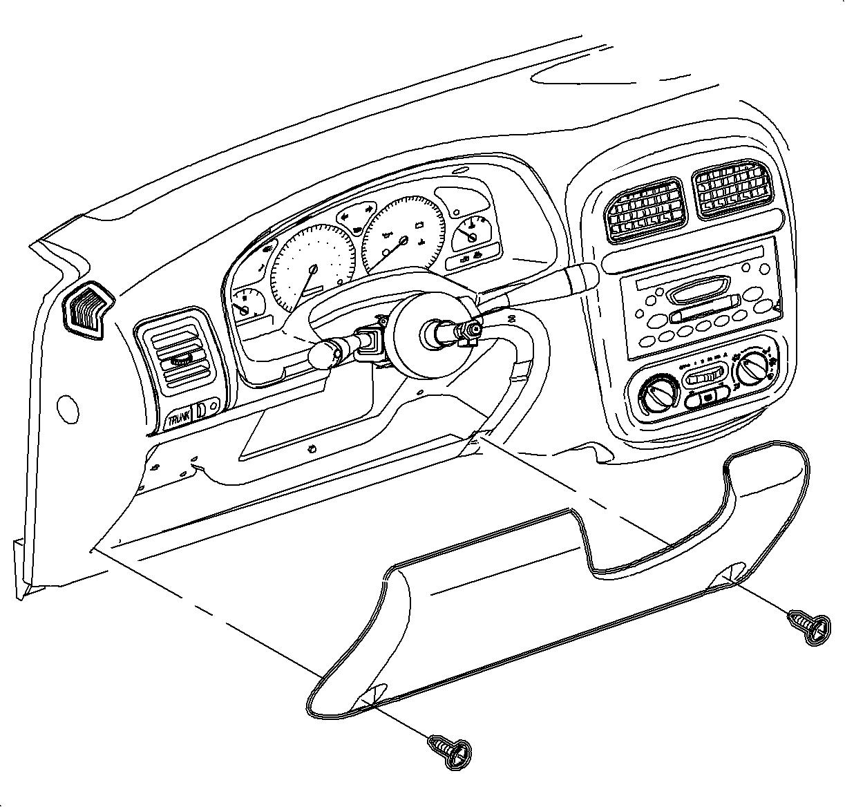
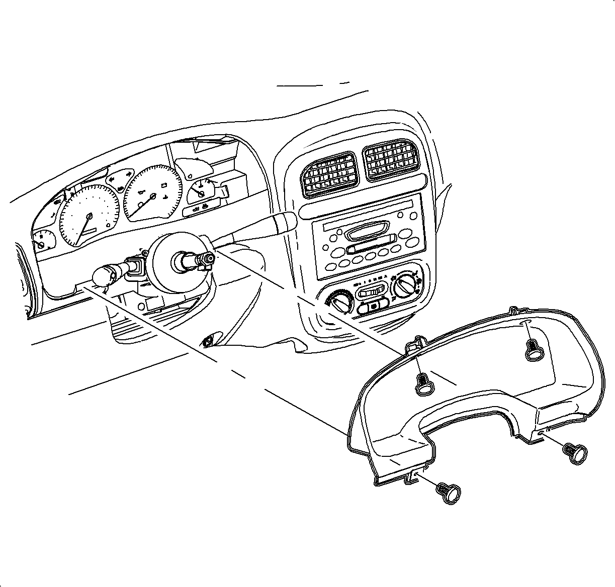
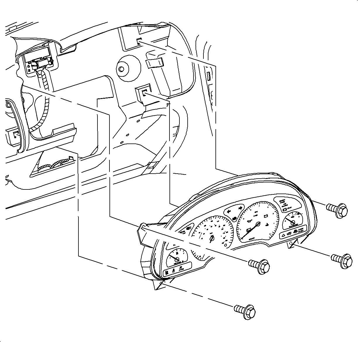
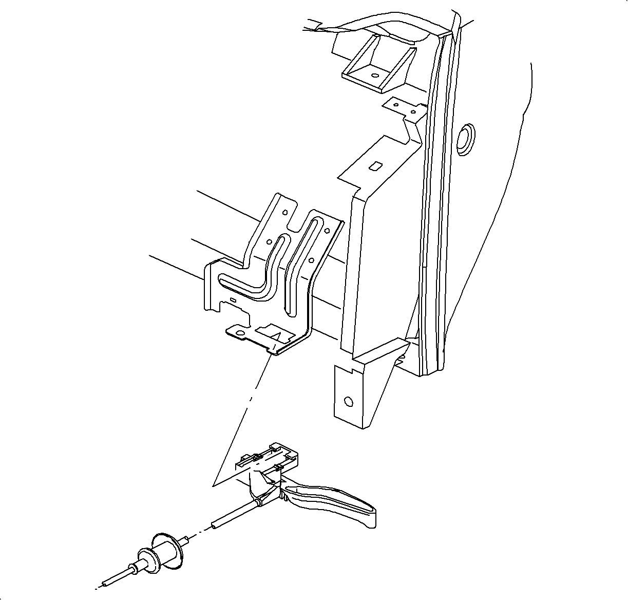
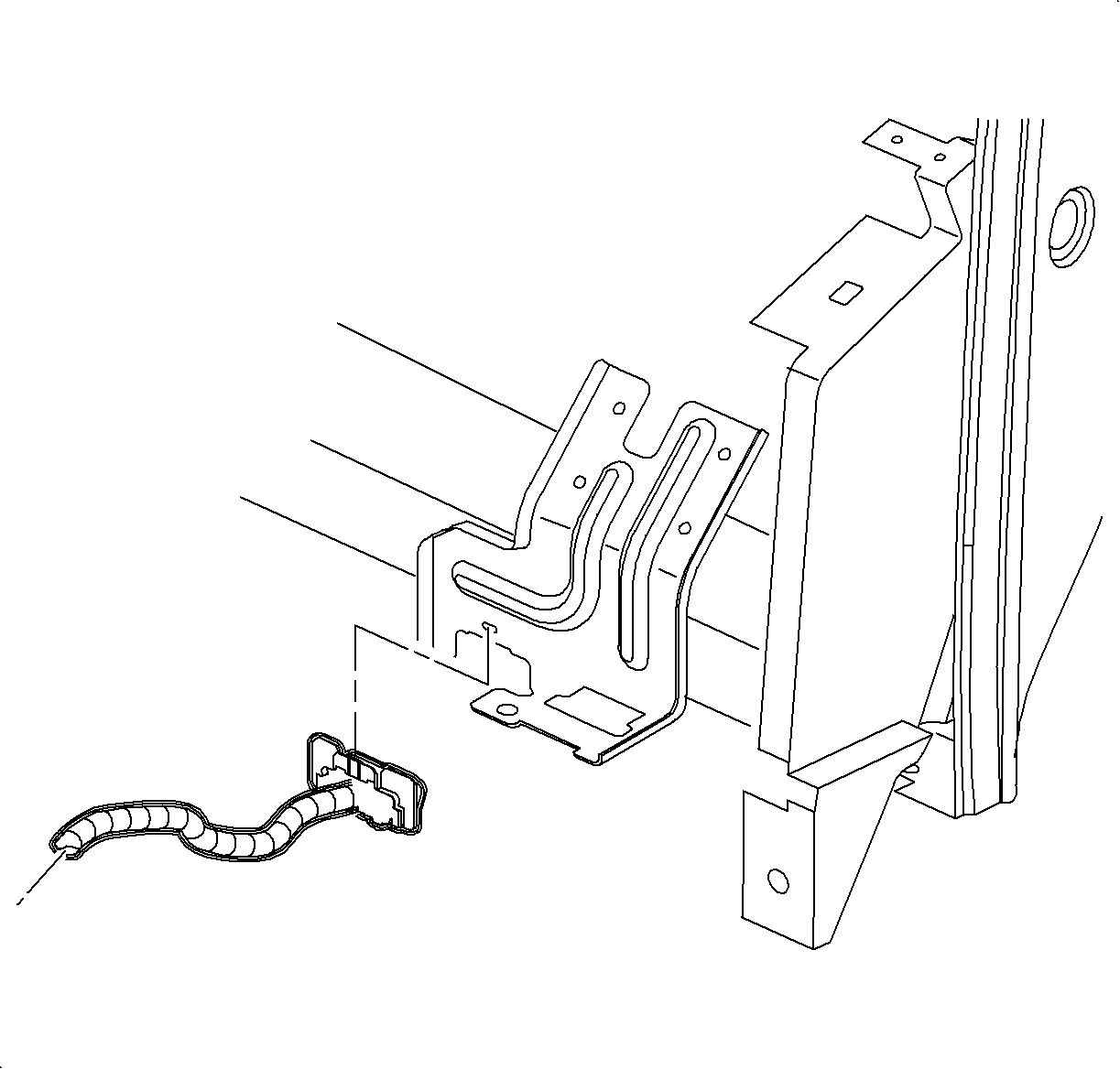
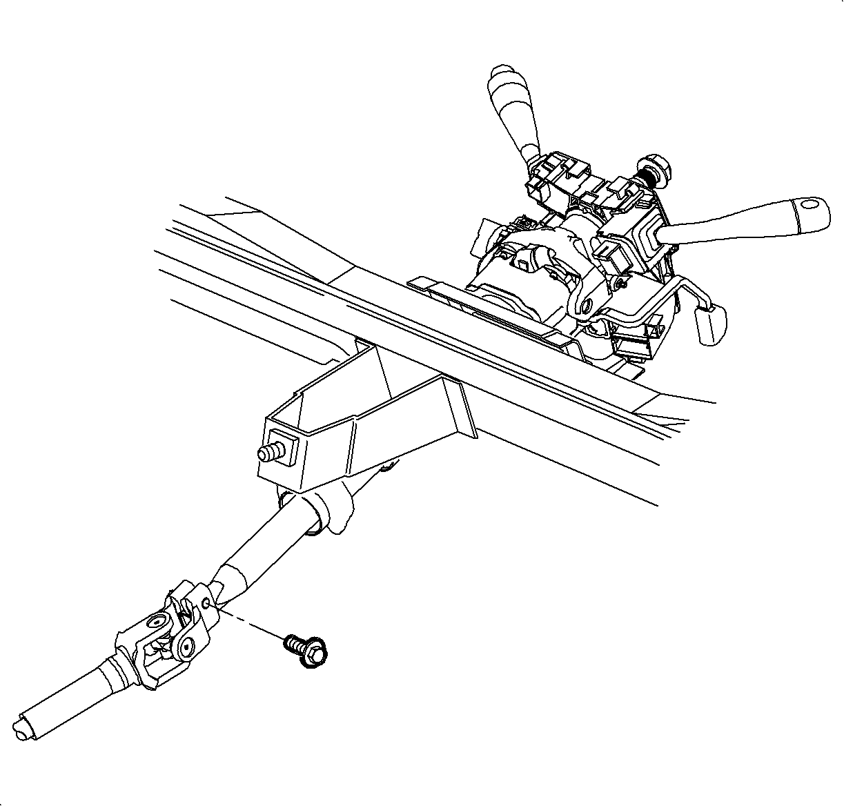
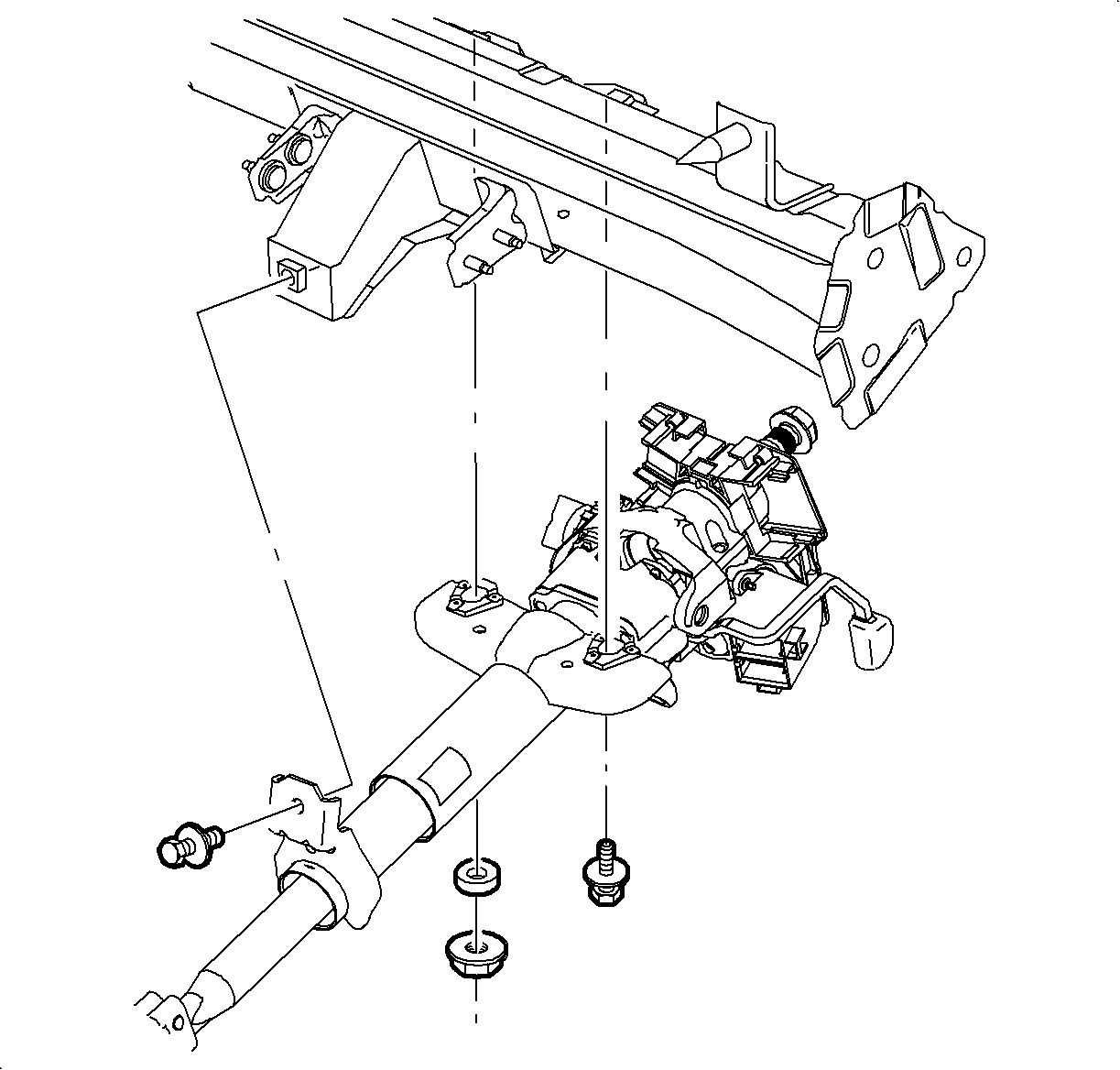
Important: Behind the nut is a plastic locator for the steering column. This piece will center the steering column in front of the driver in the event of an accident.
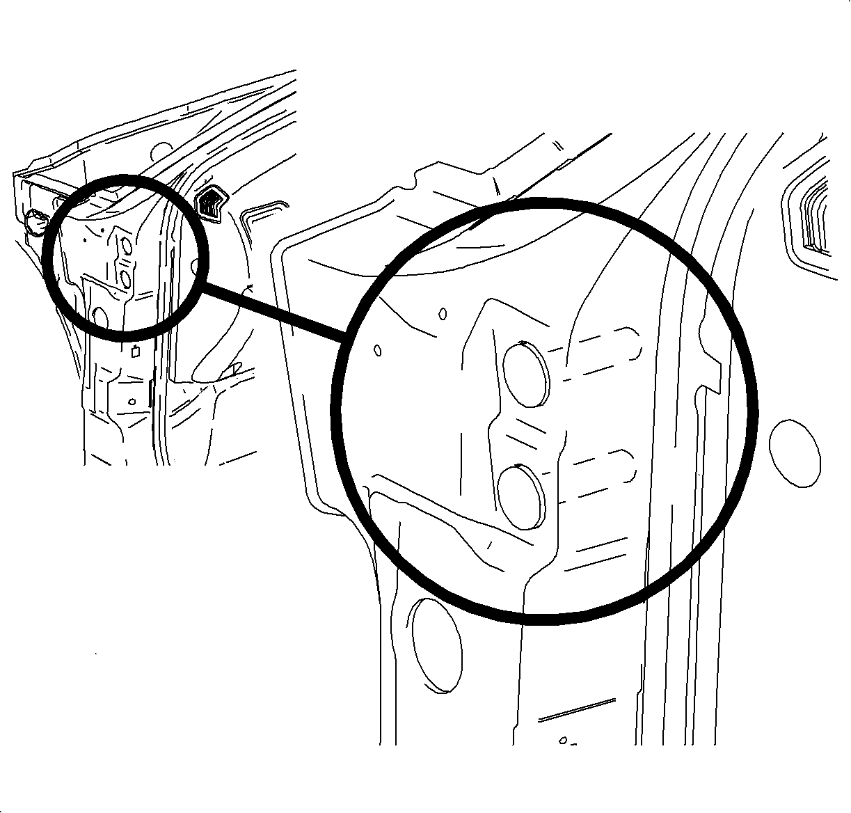
Notice: Use a T30 Torx® socket to prevent stripping bolt.
Notice: Use a T30 Torx® socket to prevent stripping bolt.
Installation Procedure
- Install the module into the vehicle.
- Install the HVAC module to the front of the dash and hand start the bolts.
- Remove the filter housing seal using a small flat-blade screwdriver.
- Install a new filter housing seal.
- Install the filter housing and screws.
- Reposition the wiper module and install the bolts.
- Tighten the HVAC module to front of the dash bolts.
- Install the condensate drain tube and the bolt.
- Install the cabin air filter paying special attention to the air flow direction indicator.
- Rotate the locking tabs to secure the air filter in place.
- Install the cowl screen and the fasteners.
- Close the filter access door.
- Install the beam to steering column braces. Using a large screwdriver, pry the steering column braces apart to clear the beam studs and slide the beam forward to locate the studs into the holes.
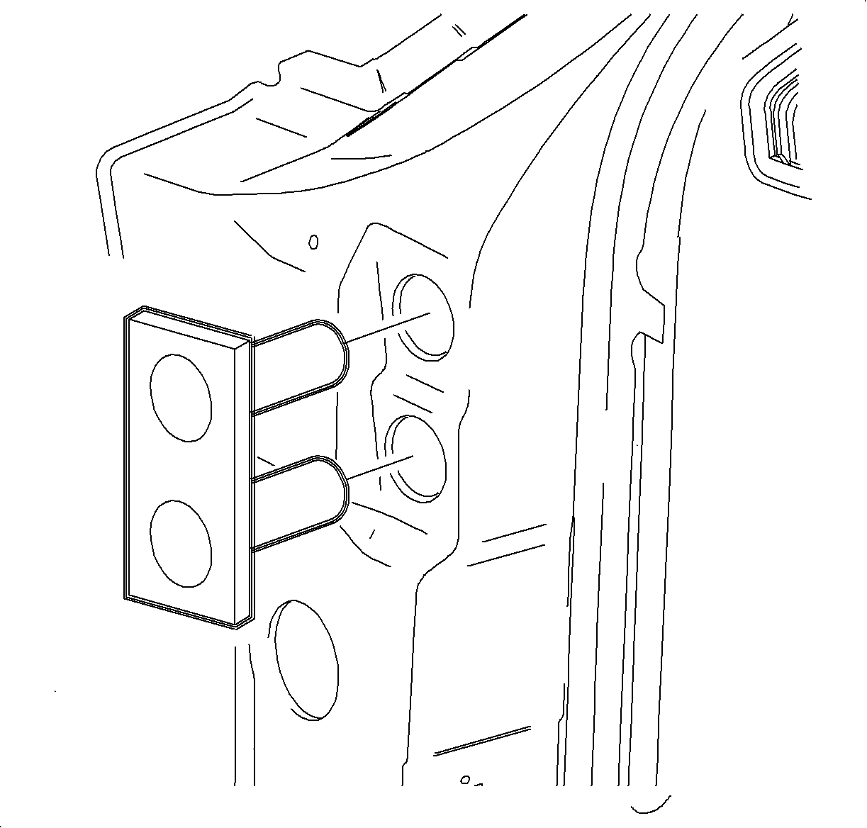
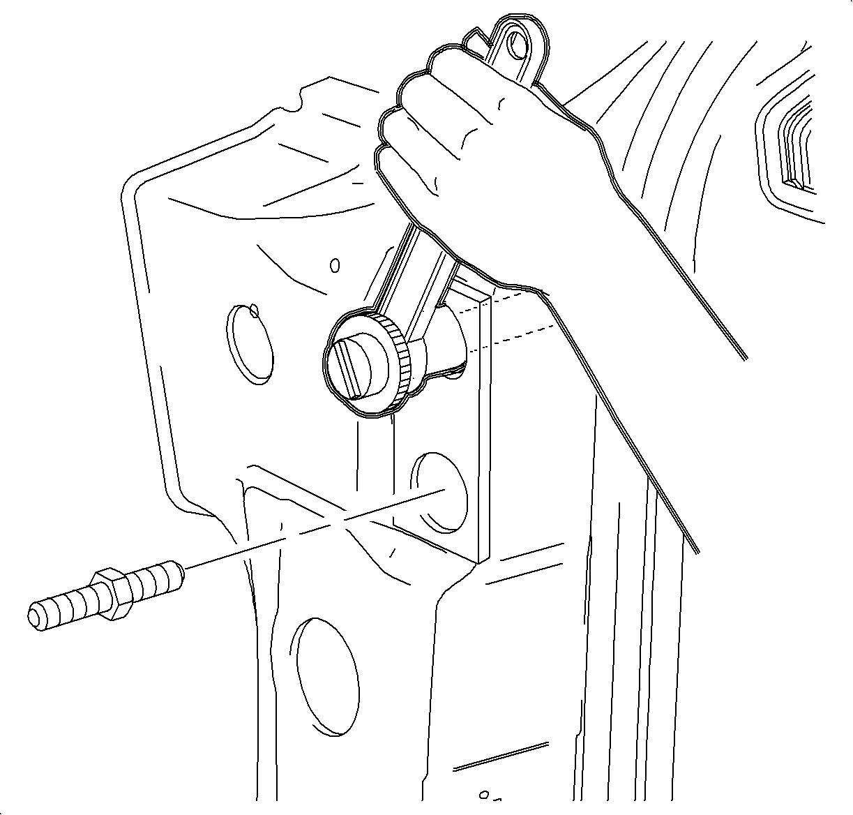
- Install the J 43894 4 into the A-pillar beam bolt holes. The tool flange should fit tight to the A-pillar surface when completely installed. This tool is needed to prevent accidentally dropping a bolt inside A-pillar.
- Install the upper and the lower inner beam bolts.
- Remove the J 43894 .
- Install the upper and the lower outer beam bolts.
- Install the black plastic bolt caps.
- Repeat the beam bolt installation procedure on the passenger's side.
- Install the I/P beam to steering column brace nuts.
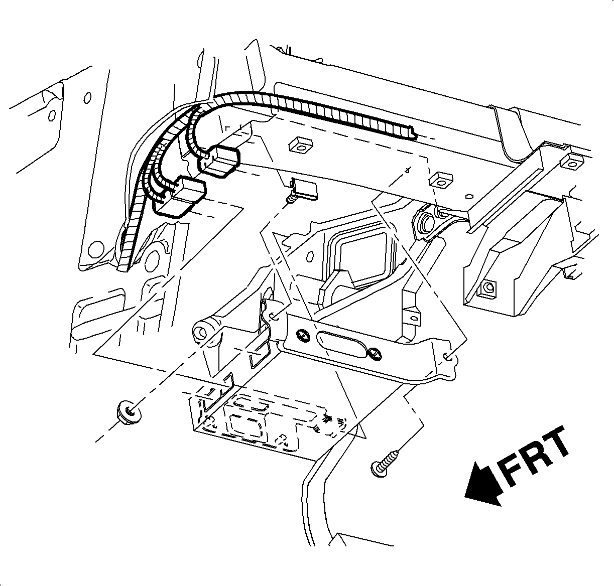
- Install the I/P harness rosebud connectors to the I/P beam.
- Connect the HVAC module electrical harness to the I/P harness.
- Route the temperature door cable around the outside of the right H-brace.
- For vehicles equipped with advanced audio system only -- Connect the amplifier wire harness connectors to the amplifier.
- Slide the amplifier onto the clutch pedal bracket.
- Position the amplifier to the I/P beam. Install the fasteners.
- Install the upper and the lower steering column mount bolts and the upper steering column mount nut along with the locator.
- Connect the intermediate shaft and install the pinch bolt.
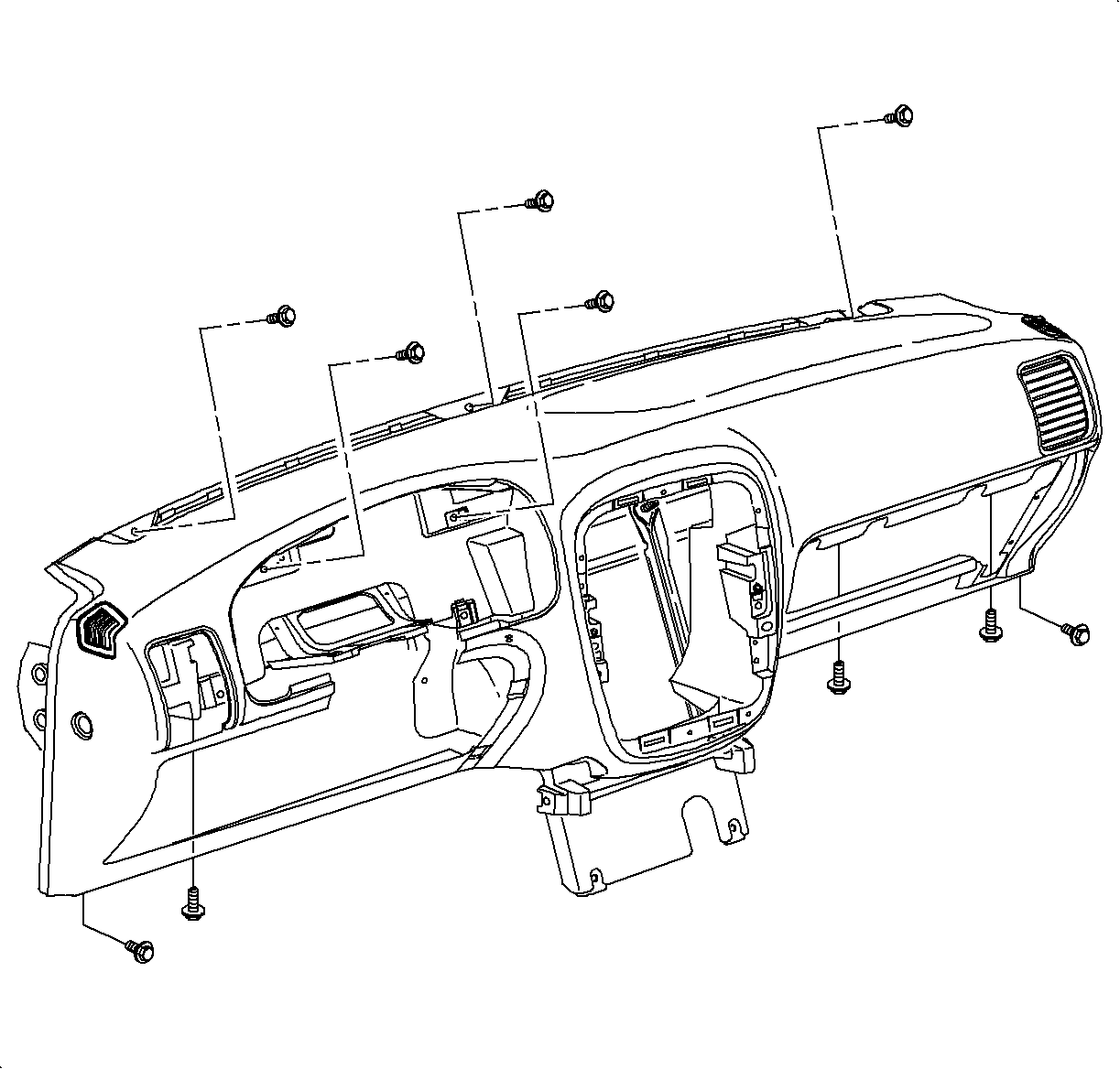
- Position the I/P to vehicle.
- Loosely install the 3 upper I/P fasteners at the W/S defroster location.
- Loosely install the I/P fasteners at the cluster.
- Loosely install the I/P fasteners at the glove compartment.
- Loosely install the I/P fasteners at the left side to the beam.
- Loosely install the I/P fasteners at the end brackets.
- Tighten all the fasteners.
- Secure the I/P harness to the I/P at the locations where clips were removed.
- Attach the electrical harness to the I/P at the center outlet location.
- Install the cluster harness to the I/P ensuring that the harness is secured into the I/P retainer.
- Install the cluster into the I/P housing ensuring that the cluster harness is connected. Install and tighten the fasteners.
- Install the cluster trim plate and the fasteners.
- Position the I/P filler to the instrument panel and push at the attaching clip locations to secure the bolster to the I/P.
- Reposition the steering wheel.
- Connect the left side A/C outlet switch harness and install an A/C outlet with a fastener.
- Snap the hood release handle bracket into the I/P.
- Install the diagnostic connection by snapping it into the bracket.
- Install the left side HVAC lower outlet with retainer.
- For vehicles equipped with standard HVAC only - Rotate the HVAC control temperature knob to full hot position.
- Install the cable eyelet onto the control head pin and install the cable housing flag into the slot in the control head until it engages locking tab.
- Install the electrical connectors to the control head.
- Install the control head to I/P screws.
- For vehicles equipped with standard HVAC vehicles - Place the temperature control knob in the full cold position.
- Rotate the temperature door lever fully forward and press the cable housing into the retaining clip.
- Cycle the control head temperature lever from full cold to full hot to verify proper operation.
- Connect the radio ground strap spade terminal, electrical connectors, and antenna to the rear of the radio.
- Install the radio by sliding it into the guides on the instrument panel.
- Install and tighten the screws.
- Connect the center trim plate switch harnesses to the switches and snap the center trim plate into the I/P.
- Install the glove compartment bin partially into the opening.
- Secure the BCM module to glove compartment bin slots.
- Route the glove compartment lamp wiring harness through the lamp opening and connect the glove compartment lamp wiring harness to the glove compartment lamp.
- Snap the lamp into glove compartment bin.
- Install the glove compartment bin to the I/P with fasteners.
- Install the heater outlet with retainer to the glove compartment bin.
- Install the lower dash insulator with retainers.
- Install the glove compartment door with fasteners.
- Function the glove compartment lamp and the glove compartment door to ensure proper operation.
- Install the I/P bracket.
- Position the console into the vehicle. Route the shifter/PRNDL boot through the console opening.
- Install the console front fasteners.
- Move the front seats forward and install the console rear fasteners.
- For vehicles equipped with an automatic transaxle only - Snap the PRNDL cover into the console opening.
- For vehicles equipped with a 5-speed transaxle only - Snap the shifter boot into the console opening.
- Connect the console wiring harness to the main body harness.
- Snap the console front tray into the console.
- For vehicles equipped with power windows only - Connect the power window harness to power window switch and snap the switch into place.
- Snap the park brake boot into place.
- Install the console extensions.
- Install the steering column trim cover and the attachment fasteners.
- Install the ignition switch bezel by pushing it in.
- Remove the yellow tab or tape from the SIR coil assembly.
- Route the wiring through the steering wheel and install the steering wheel onto the steering shaft noting orientation notch that locates the steering wheel in the correct position.
- Install the NEW steering wheel attachment nut.
- If equipped with cruise control, connect the cruise control switch connectors and attach the harness to the steering wheel.
- Connect the inflator module wiring harness and install the harness integral connector lock device.
- Install the inflator module into the steering wheel. Be sure to seat all 4 attachment points.
- Enable the SIR system. Refer to Enabling the SIR System in SIR.
- Install the heater inlet hose, closest to driver's side.
- Install the heater outlet hose, closest to passenger side.
- Remove the protective cap from the TXV.
- Thoroughly clean the O-ring surfaces of the TXV.
- Remove the cap and install new O-rings to the suction/liquid line assembly block.
- Lubricate the O-rings with clean mineral oil.
- Install the suction/liquid line assembly block to the TXV.
- Install the suction/liquid line assembly to the TXV nut.
- Rinse off any coolant that was spilled in the engine compartment.
- Connect the negative battery cable.
- Fill the cooling system - see Coolant Replacement in the Engine Cooling Section of the appropriate engine service manual.
- Evacuate, charge, and leak check the A/C system.

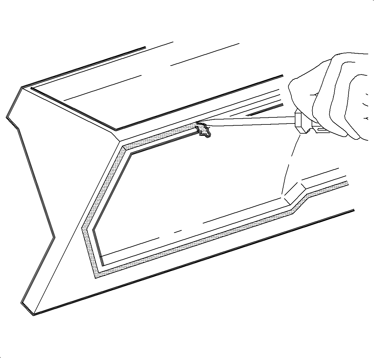
Notice: A new filter housing seal must be used whenever the filter housing is removed to prevent water from leaking into module.

Tighten
Tighten the filter housing-to-HVAC module fasteners
to 3.5 N·m (31 lb in).

Tighten
Tighten the wiper module bolts to 5 N·m
(44 lb in).

Tighten
Tighten the HVAC module-to-front of dash bolts to
4.5 N·m (40 lb in).
Tighten
Tighten the condensate drain tube bolt to 3.5 N·m
(31 lb in).


Tighten
Tighten the front of dash screen-to-front of dash
fasteners to 1.0 N·m (9 lb in).


Notice: Open drivers side door completely and install protective covering on door inner hinge area to prevent damage to paint.
Notice: On Wagons, the rear washer supply hose is routed through drivers side A-pillar. Use care not to pinch or damage hose.

Tighten
Tighten the I/P beam inner studs to 20 N·m
(15 lb ft).

Tighten
Tighten the I/P beam outer bolts to 7 N·m
(63 lb in).


Tighten
Tighten the I/P beam-to-steering column brace nuts
to 20 N·m (15 lb ft).


Tighten
Tighten the I/P audio system amplifier-to-I/P beam
fasteners to 10 N·m (89 lb in).

Important: The plastic steering column locator should be installed behind the upper steering column mount nut. This locator centers the steering column to driver in the event of an accident.
Tighten
Tighten the steering column attachment fasteners
to 30 N·m (20 lb ft).

Important: Use LOCTITE 242® Threadlocker, or equivalent, on the threads of the pinch bolt.
Tighten
Tighten the steering column intermediate shaft pinch
bolt to 30 N·m (20 lb ft).

Tighten
Tighten the I/P attachment fasteners to 20 N·m
(14 lb ft).


Tighten
Tighten the instrument cluster-to-I/P housing fasteners
to 2.3 N·m (22 lb in).

Tighten
Tighten the cluster trim plate-to-I/P cluster fasteners
to 2.2 N·m (22 lb in).


Tighten
Tighten the A/C outlet-to-I/P fasteners to 2.5 N·m
(22 lb in).


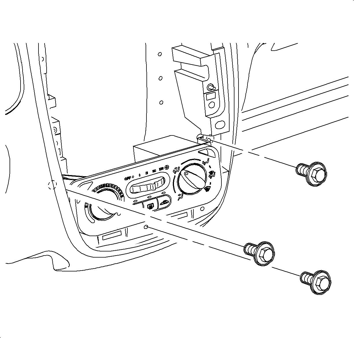
Tighten
Tighten the control head-to-I/P screws to 2.5 N·m
(22 lb in).
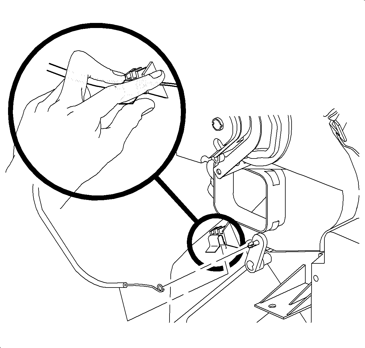

Tighten
Tighten the radio-to-I/P fasteners to 2.5 N·m
(22 lb in).
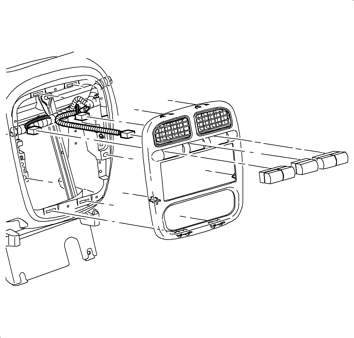


Tighten
Tighten the glove compartment bin-to-I/P fasteners
to 2.5 N·m (22 lb in).


Tighten
Tighten the glove compartment door fasteners to
2.0 N·m (18 lb in).

Tighten
Tighten the I/P bracket-to-floor panel nuts to 20 N·m
(15 lb ft).

Tighten
Tighten the console fasteners to 2.5 N·m
(22 lb in).
Tighten
Tighten the console fasteners to 2.5 N·m
(22 lb in).


Tighten
Tighten the steering column trim cover fasteners
to 4 N·m (35 lb in).

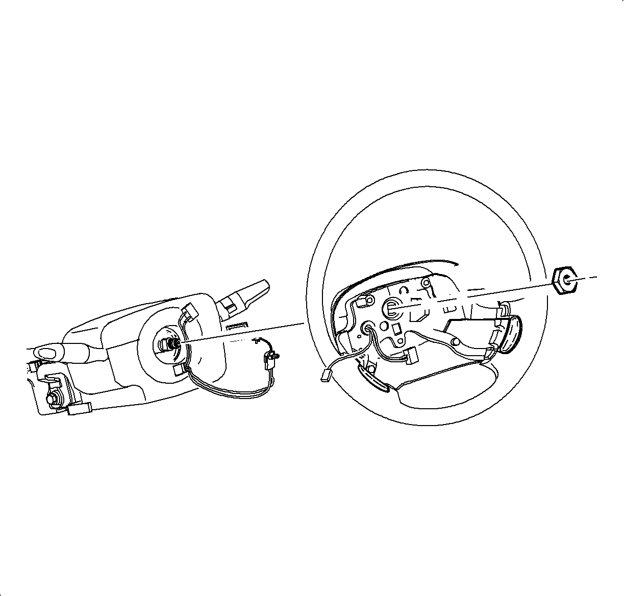
Important: A new steering wheel attachment nut must be used.
Tighten
Tighten the steering wheel attachment nut to 40 N·m
(30 lb ft).

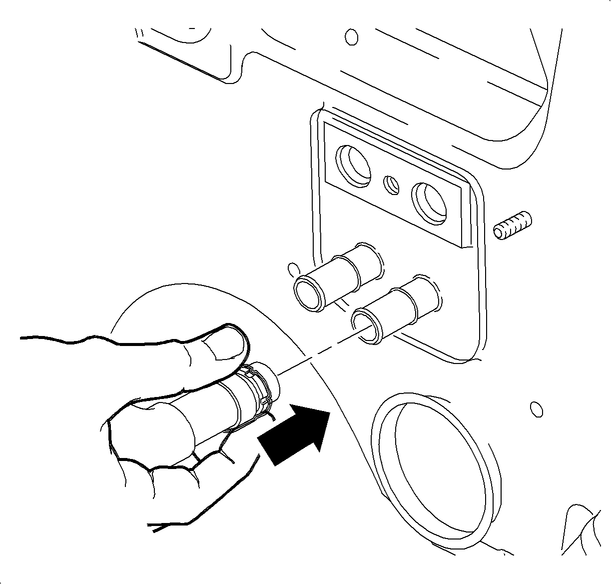
| • | Hold the hose by black quick connect collar and slide the hose onto the heater core pipe until the quick connect collar engages over the bead on the heater core pipe. |
| • | Ensure that a green band is visible in the quick connect collar. |
| • | Pull on the hose to ensure it is properly seated. |
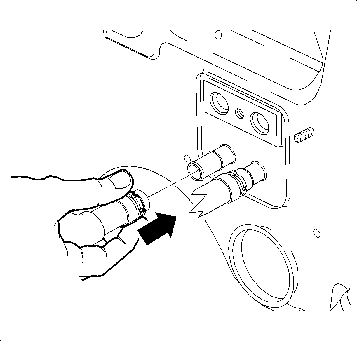
| • | Install the heater outlet hose, closest to passenger side. |
| • | Ensure that a green band is visible in the quick connect collar. |
| • | Pull on the hose to ensure it is properly seated. |

Important: On earlier vehicles a bolt was used instead of a stud/nut.
Tighten
Tighten the suction/liquid line assembly-to-TXV
bolt to 7 N·m (62 lb in).

Tighten
Tighten the battery terminal bolts to 17 N·m
(13 lb ft).
