Circuit Description
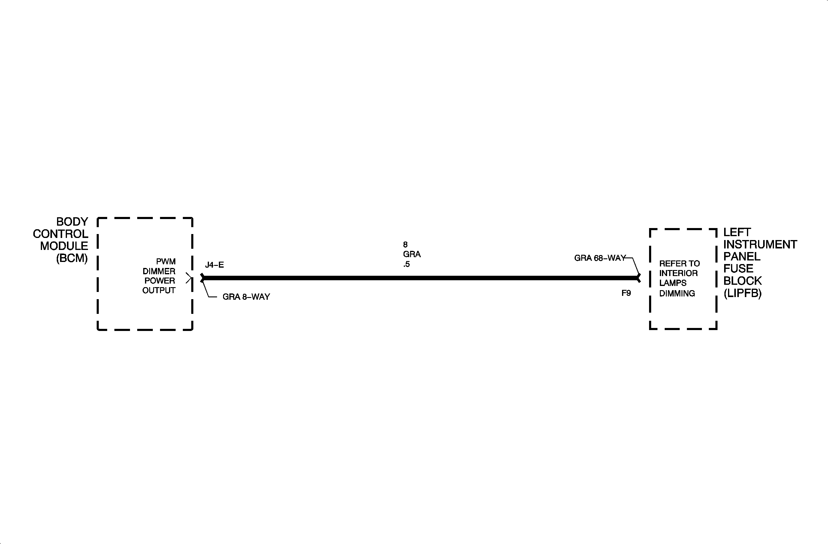
Display dimming is controlled by the body control module (BCM) based on input
received from the dimming potentiometer. The dimming potentiometer is connected between
circuit 1359 and circuit 1381. The BCM monitors these inputs and provides
a pulse width modulated (PWM) output at circuit 8 to operate the display lamps.
DTC Parameters
| • | Head lamp/parklamp switch ON |
| • | Dimming potentiometer set at minimum brightness |
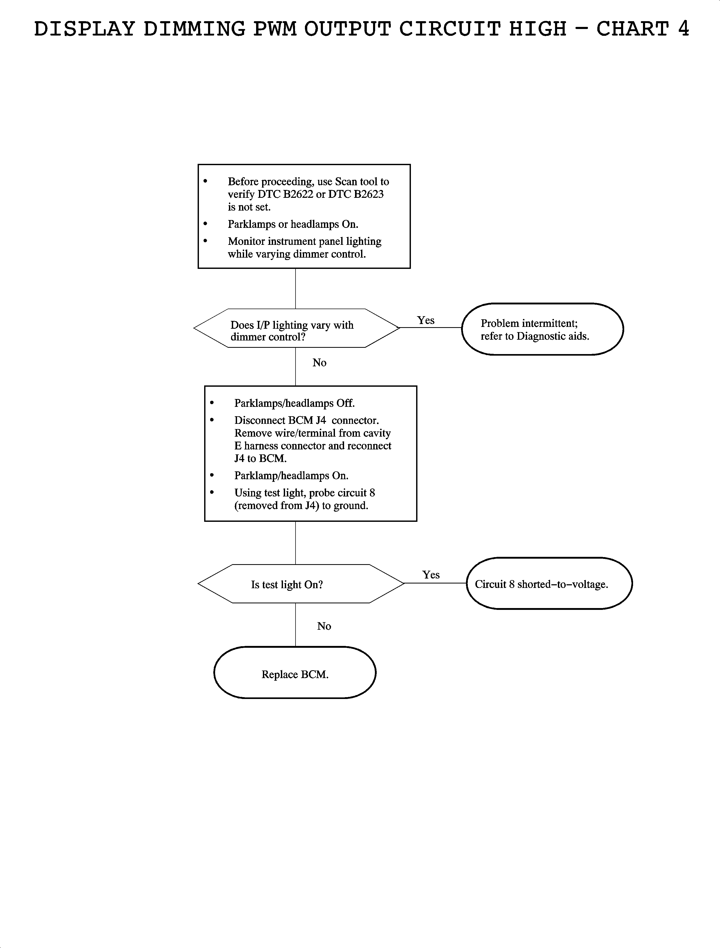
| • | Circuit 8 shorted-to-battery voltage |
Diagnostic Aids
| • | Check for poor connection at the BCM. Inspect the harness connectors for
backed-out terminals, improper terminal mating, broken connector locks, improperly
formed or damaged terminals, and poor terminal-to-wire connection (terminal crimped
over wire insulation and not conductors). |
| • | Inspect the wiring harness for damage. Check for broken or chaffed insulation. |
| • | Check for a poor connection at the dimming potentiometer. |
| • | If a fault is suspected to be intermittent, wiggling the harness wiring
may help in locating the fault. |


