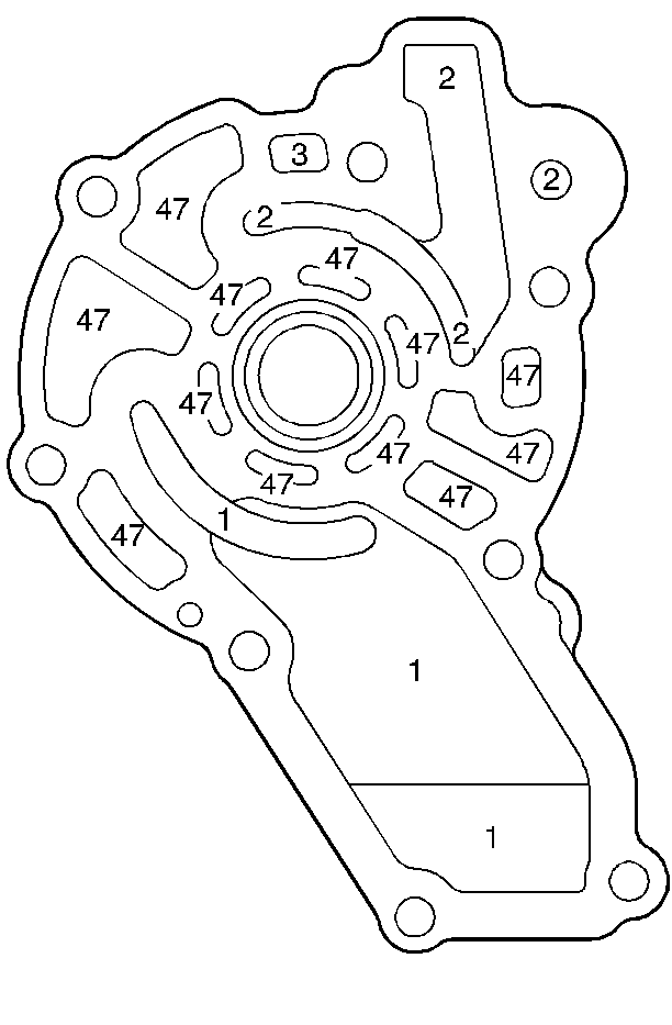
| Figure 1: |
Oil Pump Base Fluid Passages - Control Valve Body Side
|
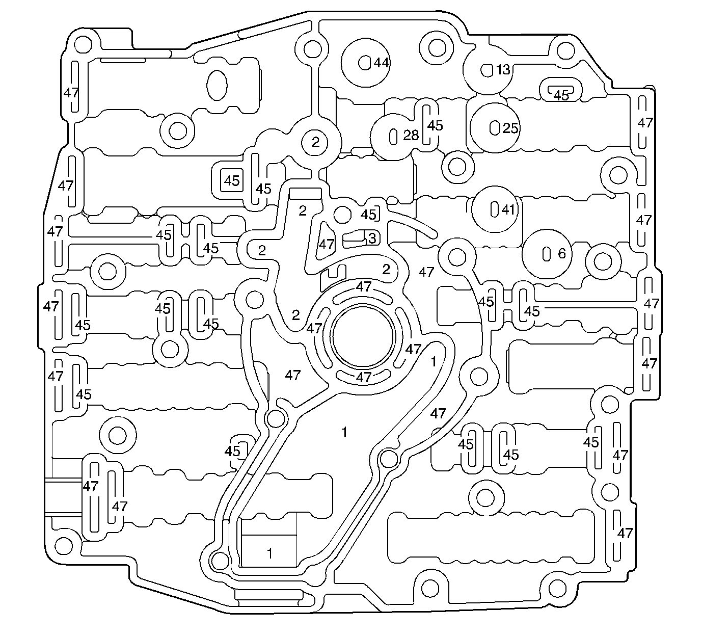
| Figure 2: |
Control Valve Body Fluid Passages (Oil Pump Base Side)
|
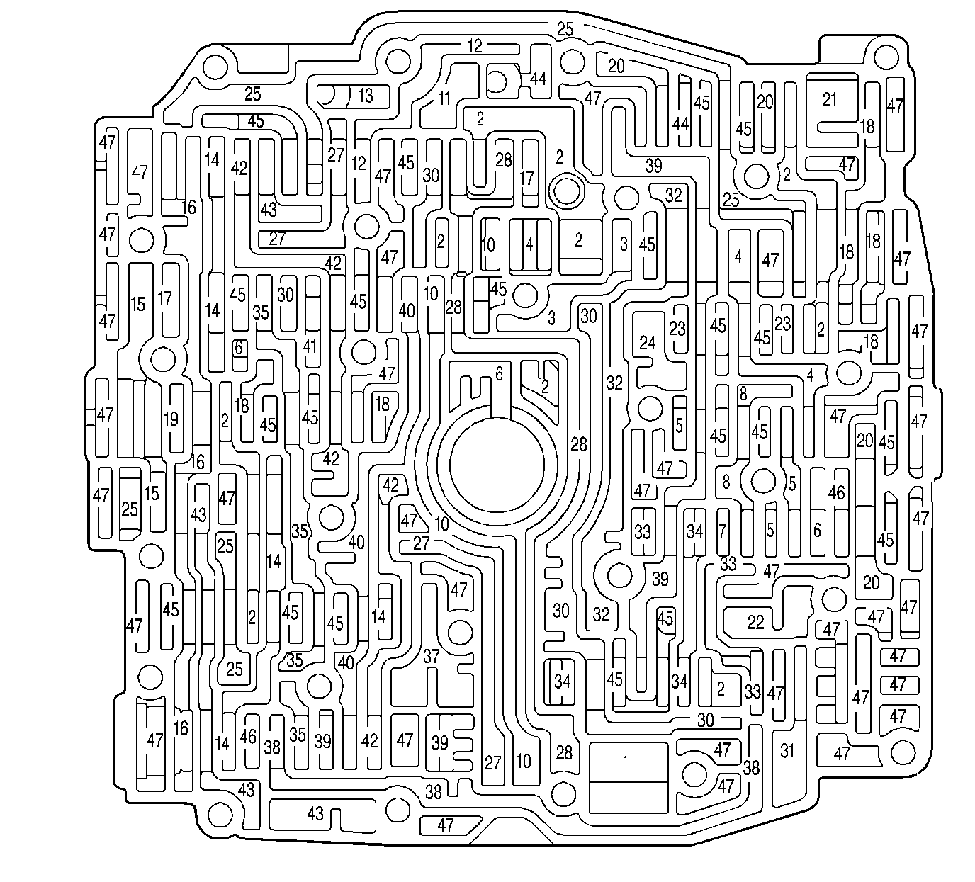
| Figure 3: |
Control Valve Body Fluid Passages (Channel Plate Side)
|
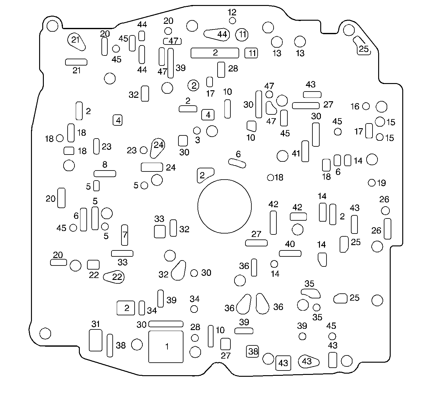
| Figure 4: |
Control Valve Body to Spacer Plate Gasket
|
| Figure 5: |
Spacer Plate
|
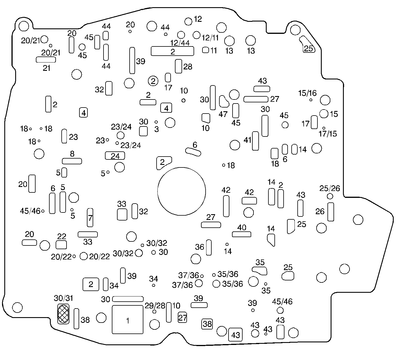
| Figure 6: |
Spacer Plate to Channel Plate Gasket
|
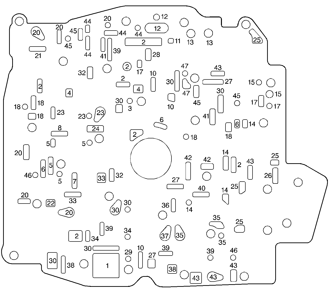
| Figure 7: |
Channel Plate Fluid Passages (Control Valve Body Side)
|
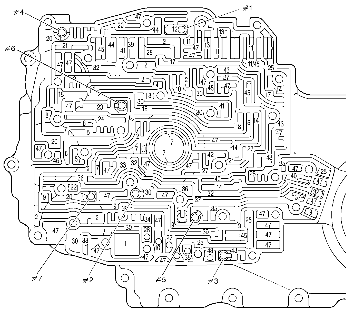
| Figure 8: |
Channel Plate Fluid Passages (Case Side)
|
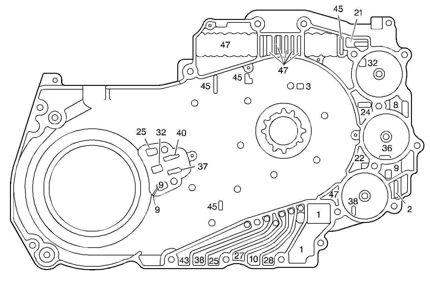
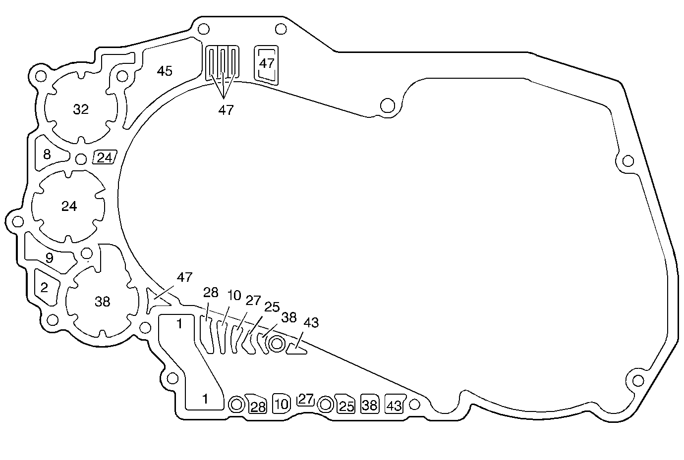
| Figure 9: |
Channel Plate to Case Gasket
|
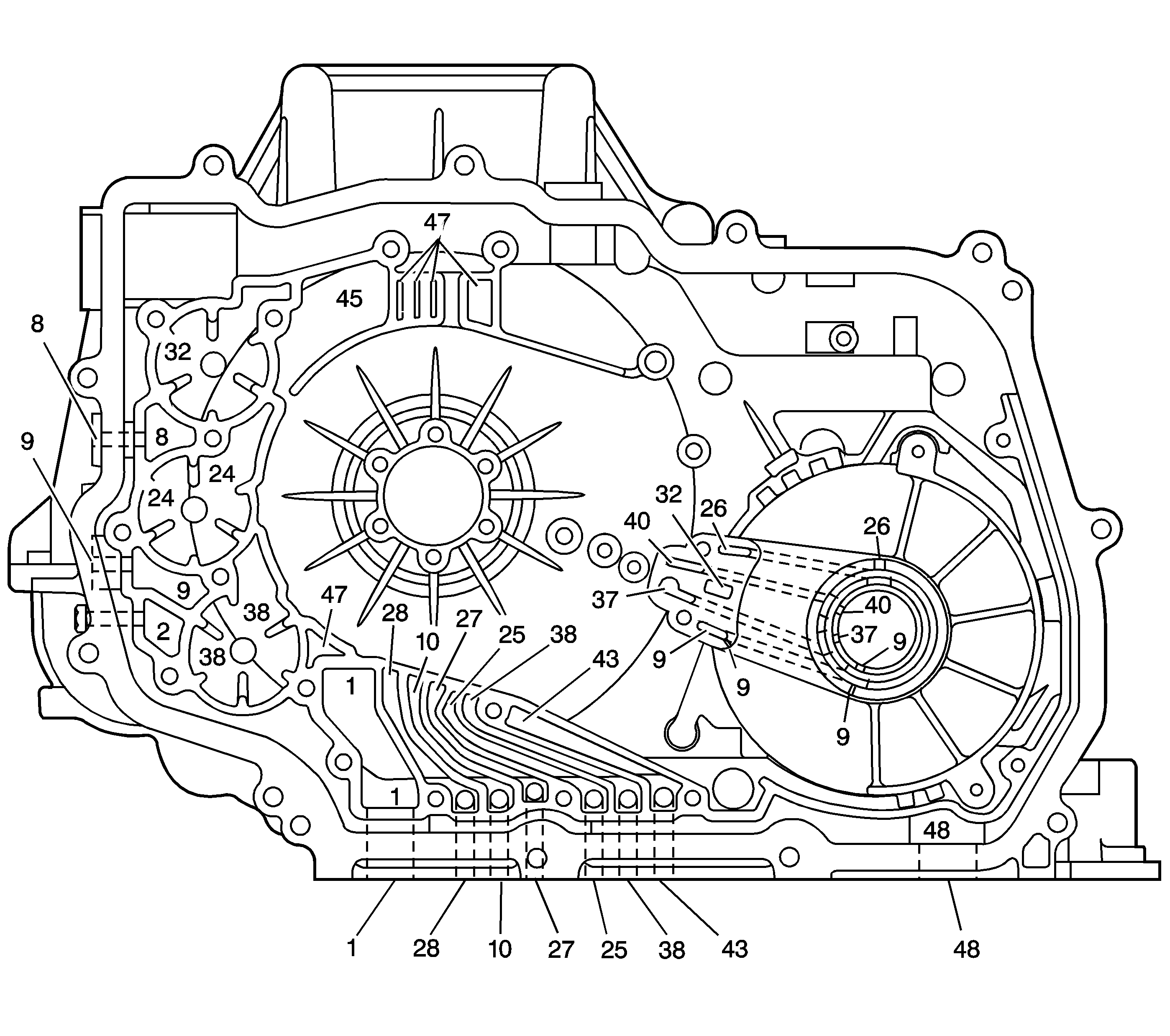
| Figure 10: |
Case and Driven Sprocket Support Fluid Passages (Channel Plate Side)
|
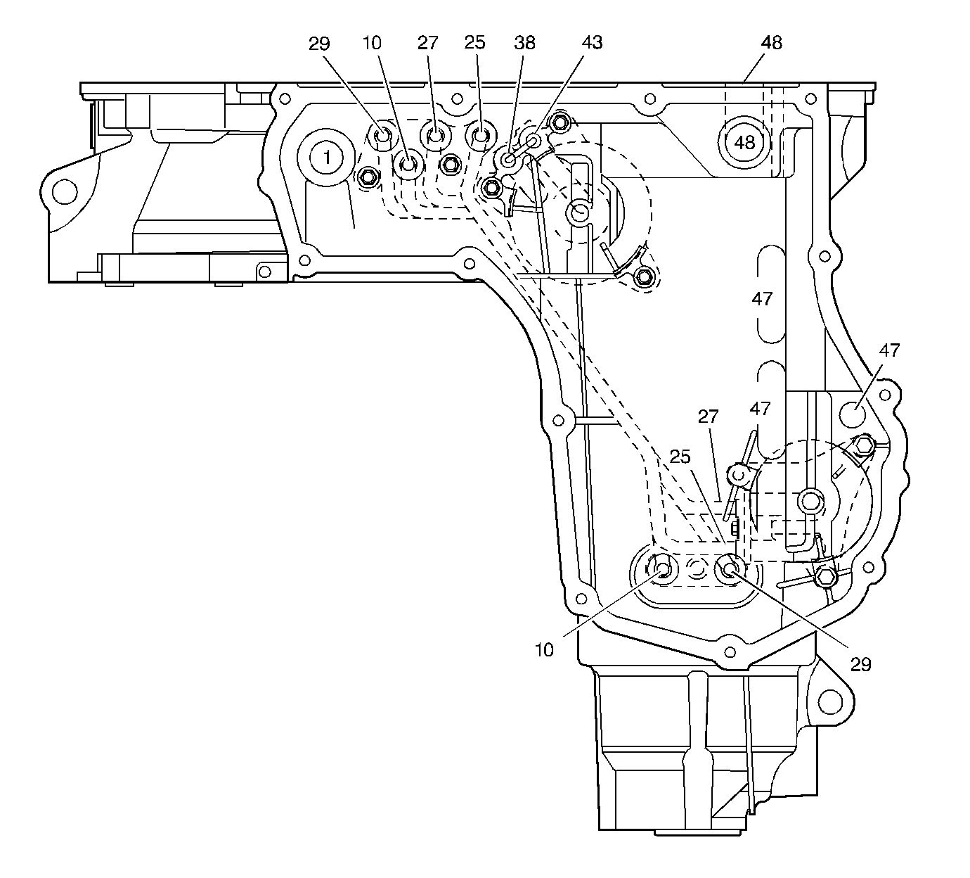
| Figure 11: |
Case Fluid Passages - Bottom
|
| Figure 1: |
Oil Pump Base Fluid Passages - Control Valve Body Side

|
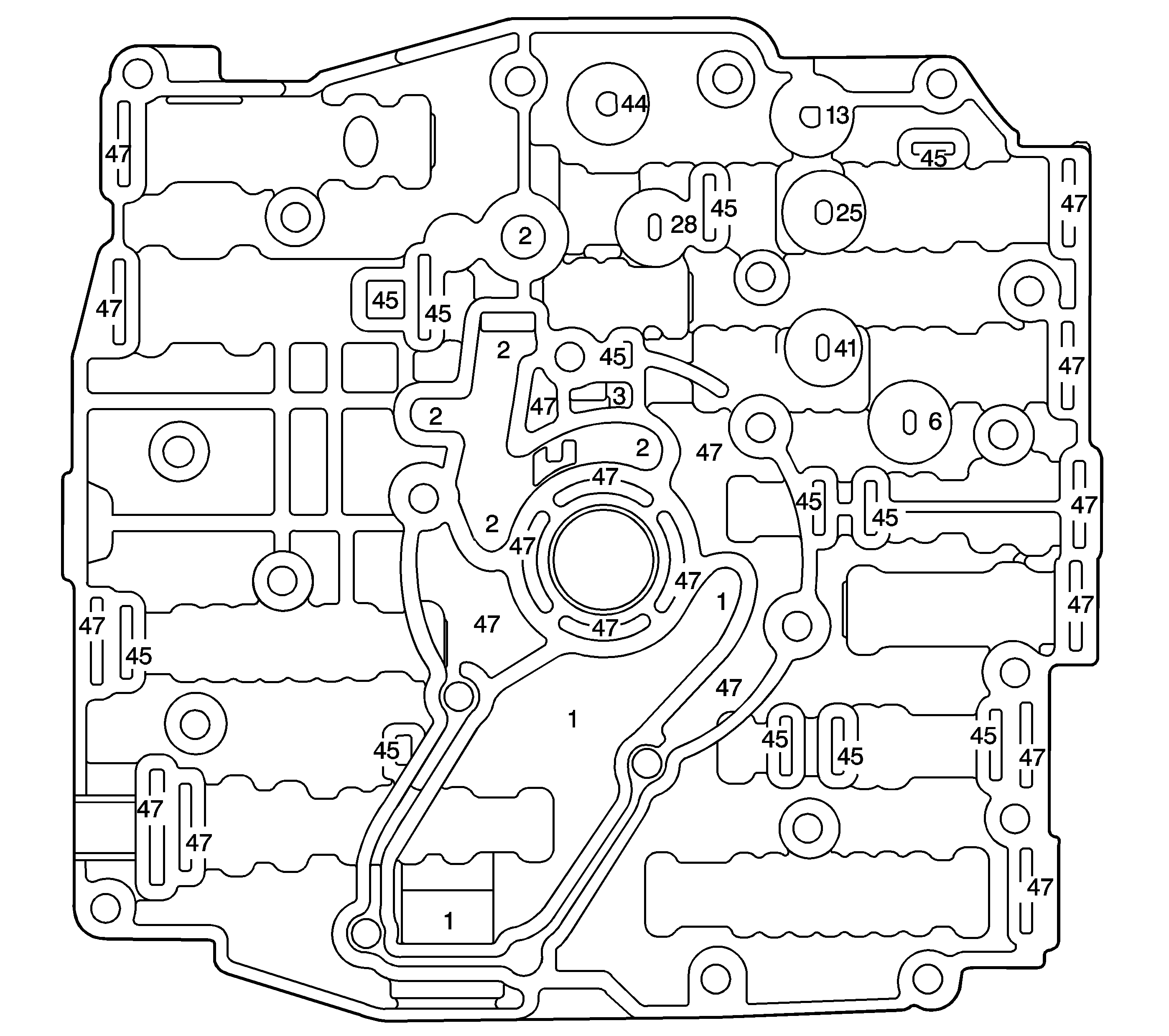
| Figure 2: |
Control Valve Body Fluid Passages - Oil Pump Base Side
|
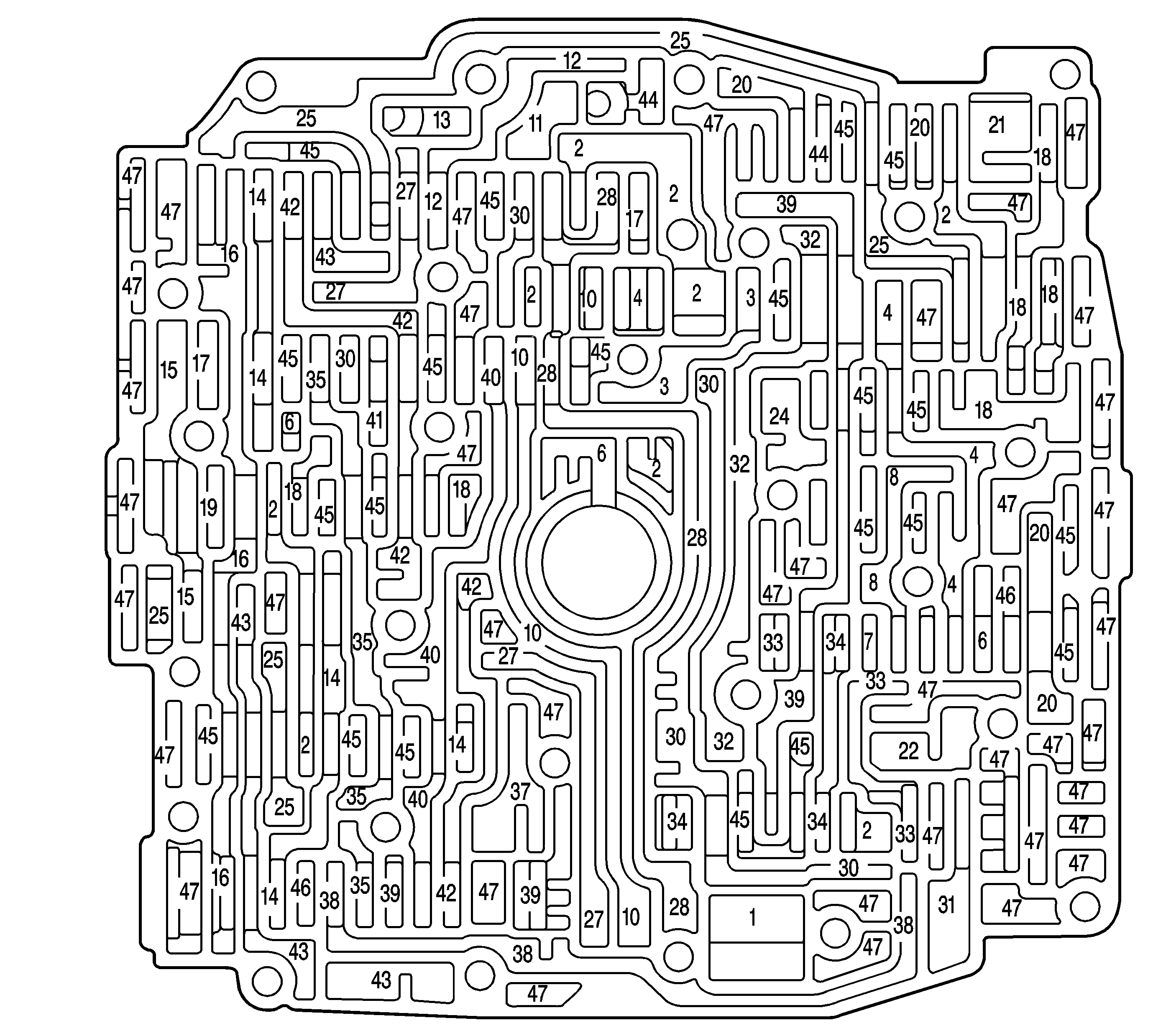
| Figure 3: |
Control Valve Body Fluid Passages (Channel Plate Side)
|
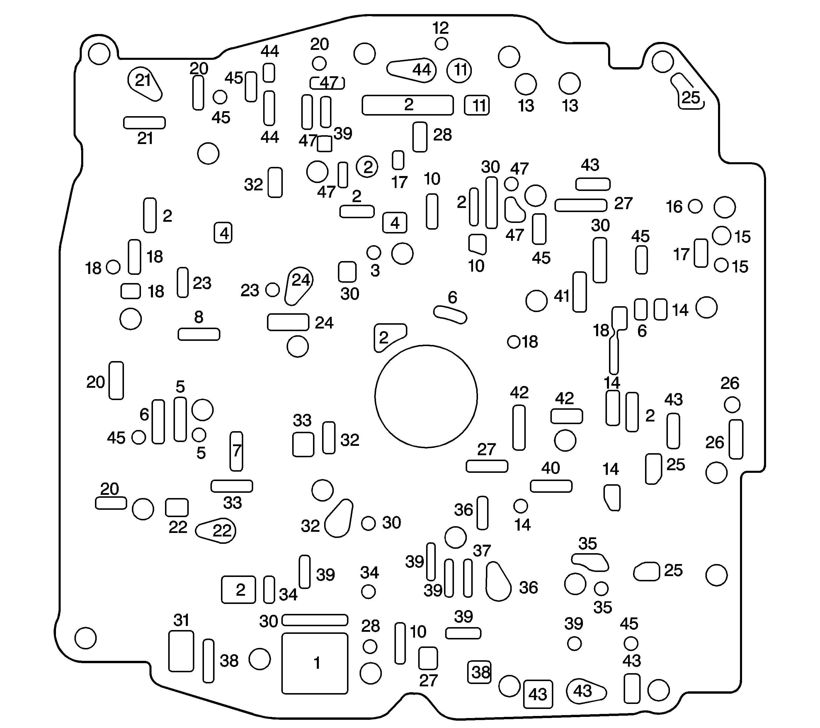
| Figure 4: |
Control Valve Body to Spacer Plate Gasket
|
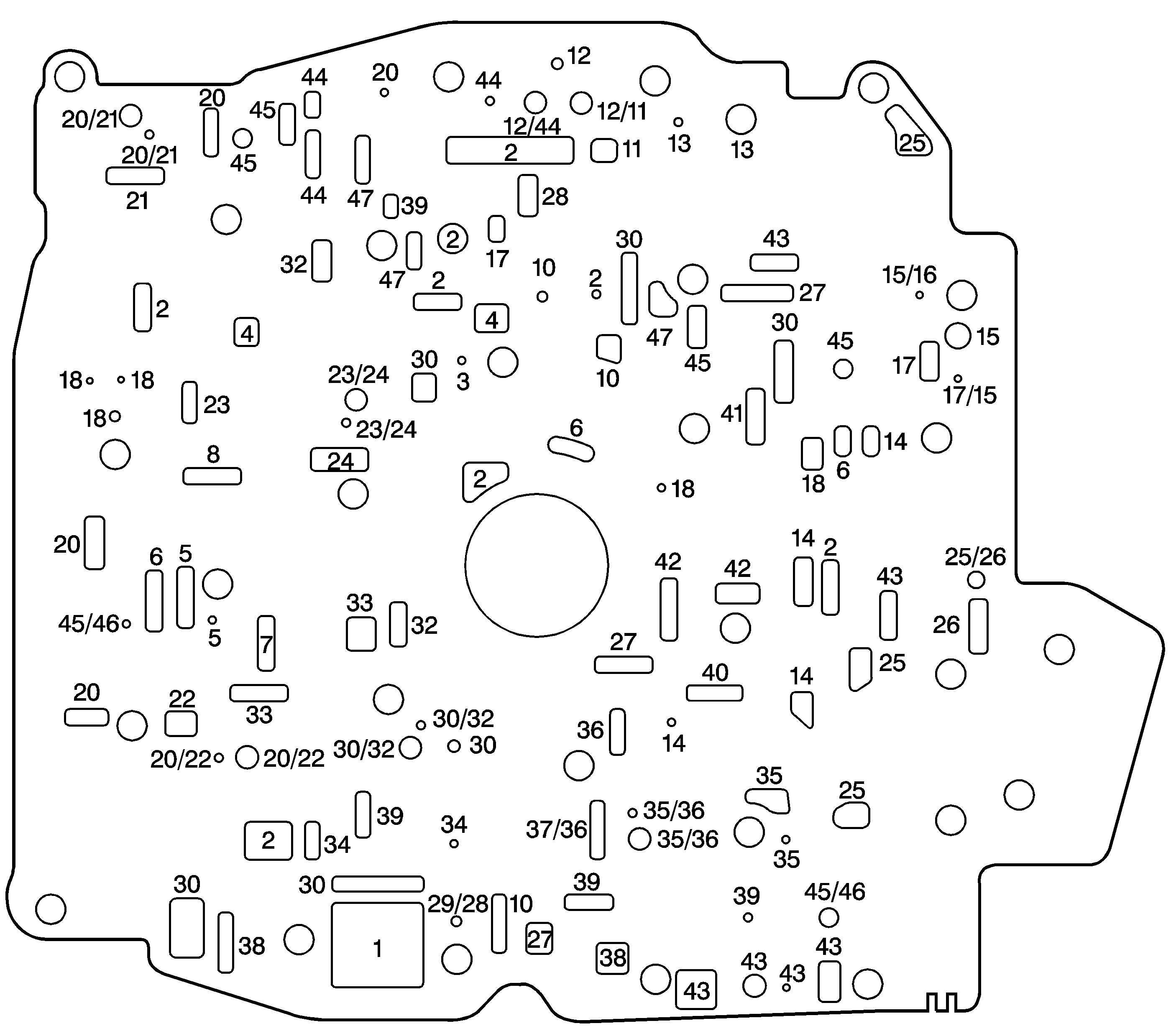
| Figure 5: |
Spacer Plate - Without Electronic Range Select Mode
|
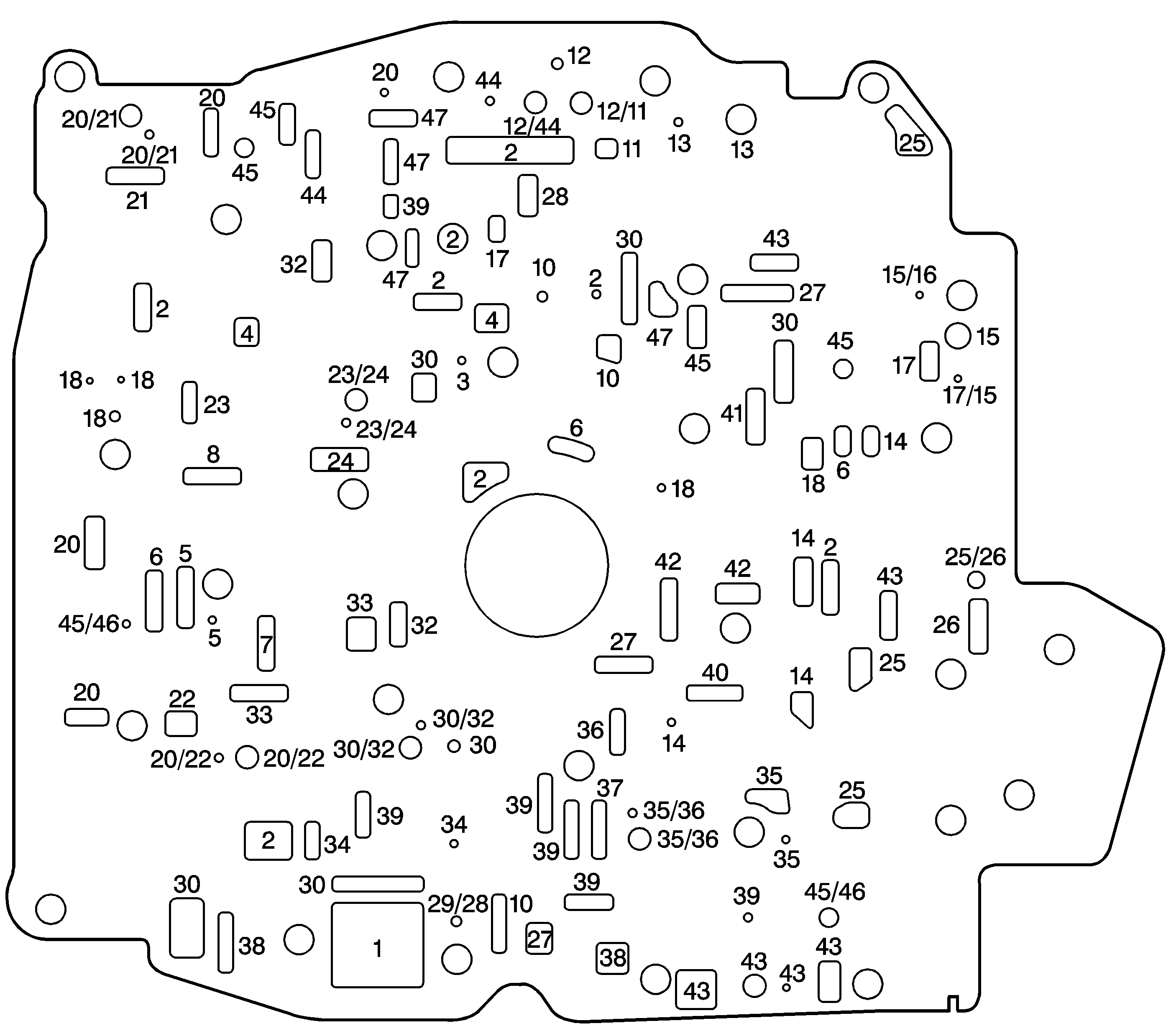
| Figure 6: |
Spacer Plate with Bonded Gaskets - With Electronic Range Select Mode
|
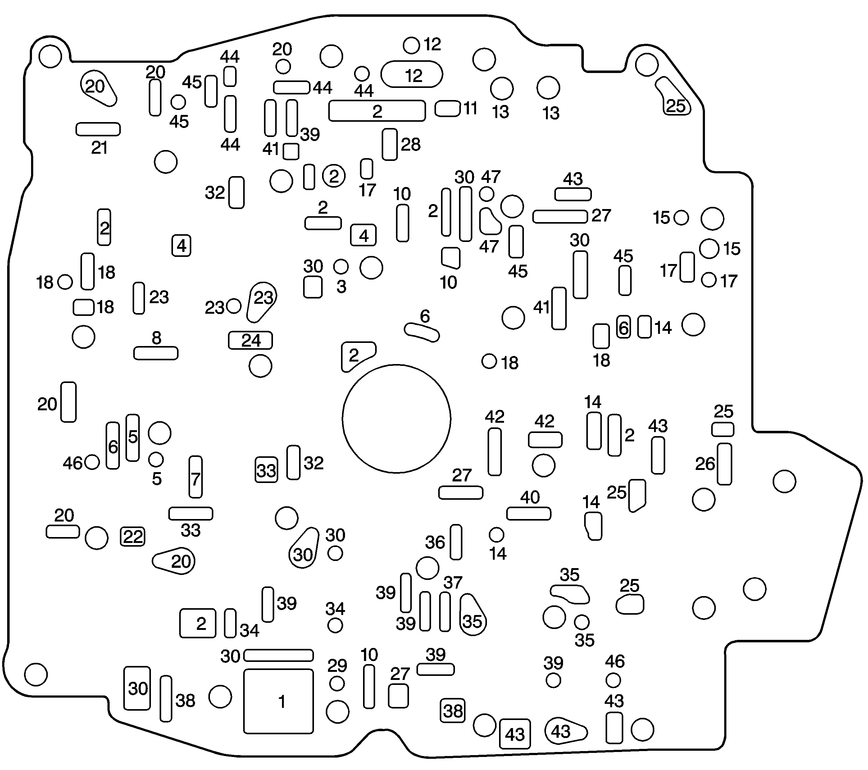
| Figure 7: |
Spacer Plate to Channel Plate Gasket
|
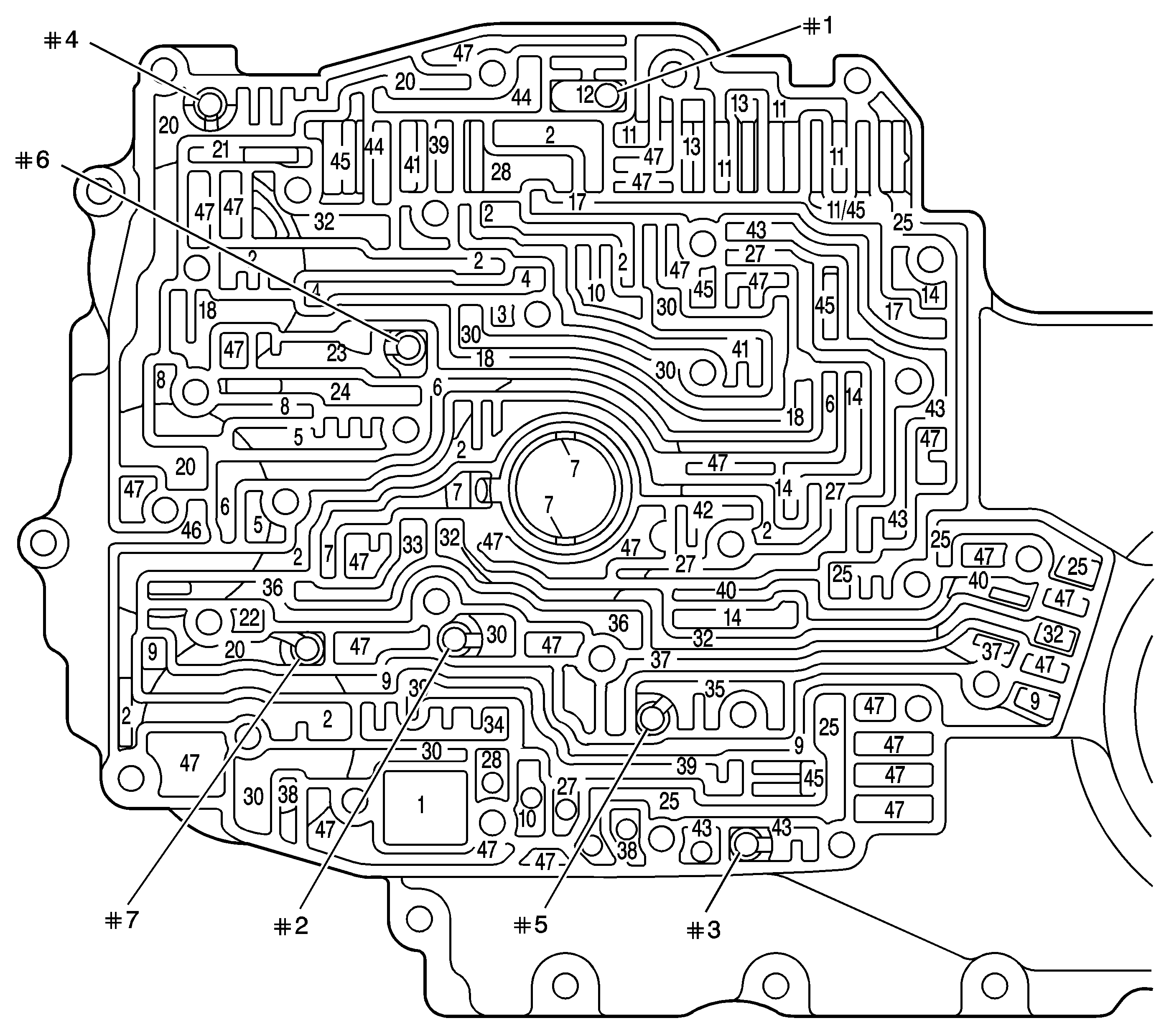
| Figure 8: |
Channel Plate Fluid Passages (Control Valve Body Side)
|
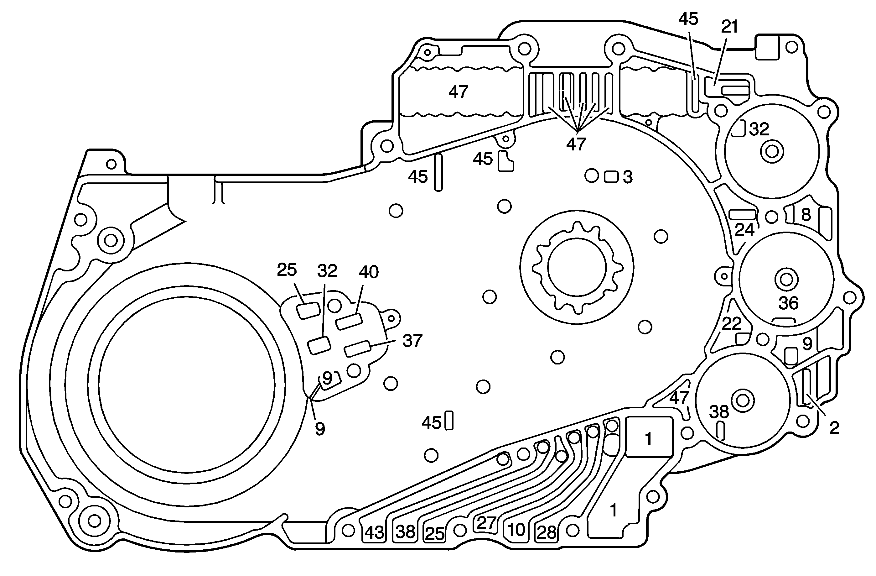
| Figure 9: |
Channel Plate Fluid Passages - Case Side
|
| Figure 10: |
Channel Plate to Case Gasket

|
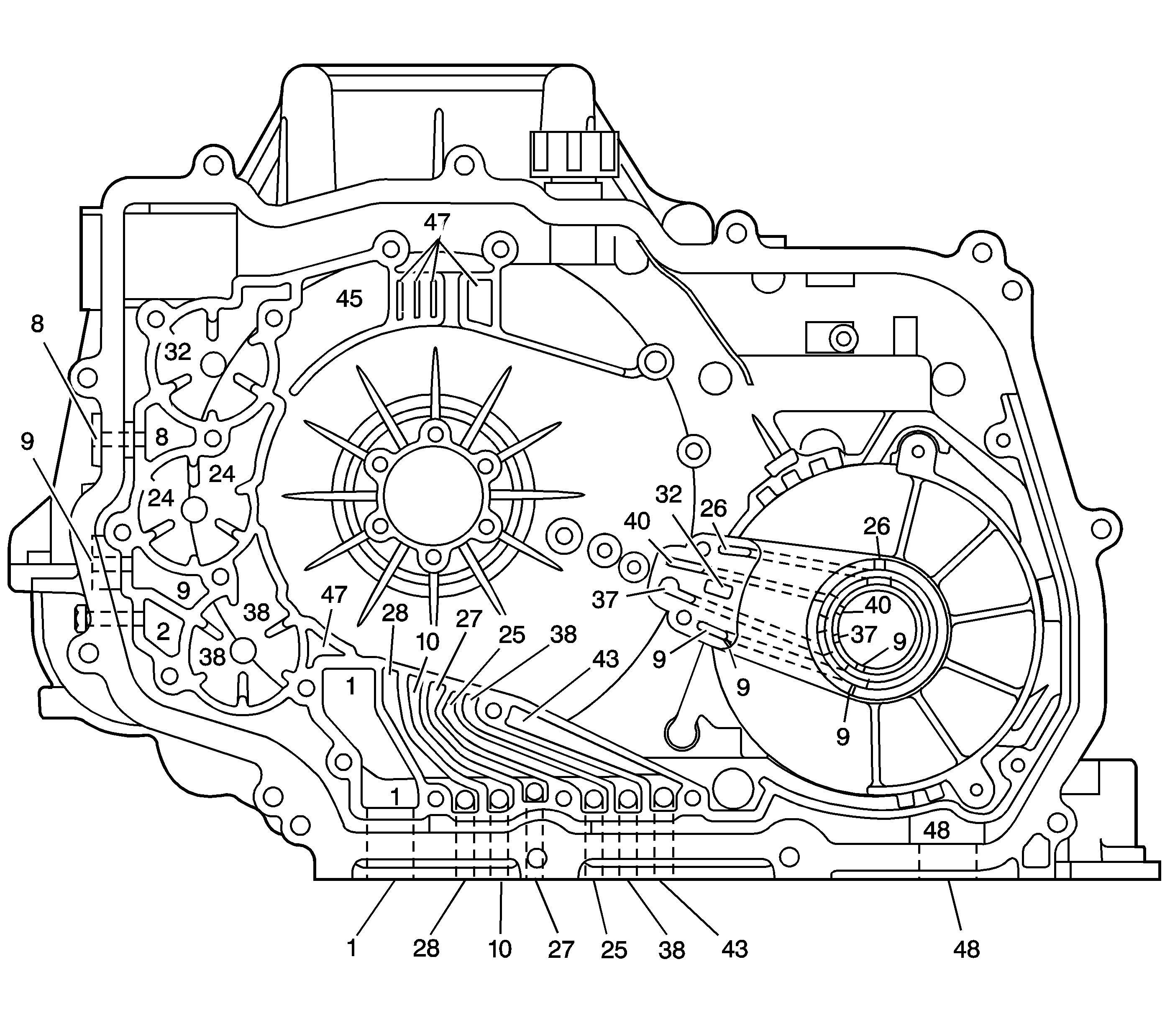
| Figure 11: |
Case and Driven Sprocket Support Fluid Passages - Channel Plate Side
|
| Figure 12: |
Case Fluid Passages - Bottom

|


