
| Subject: | Revised Service Procedure Regarding Stop Lamp Switch and Cruise Brake Switch
Adjustment |
| Models: | 2000-2001 Saturn L-Series Vehicles |
Purpose
The purpose of this bulletin is to provide an updated service procedure for
Stop Lamp Switch and Cruise Brake Switch Adjustment.
The following service procedure affects the current adjustment procedure in
the following service manuals:
| • | 2000/2001 L-Series Brakes Service Manual |
| • | 2000 L-Series (L61) Engine Service Manual |
| • | 2001 L-Series (L61) Engine Service Manual |
| • | 2000 L-Series (L81) Engine Service Manual |
| • | 2001 L-Series (L81) Engine Service Manual |
| | Important: It is important when adjusting the Stop Lamp Switch or Cruise Brake Switch to
use only the procedure outlined in this bulletin. Disregard all other adjustment procedures.
|
STOP LAMP/CRUISE BRAKE SWITCH ADJUSTMENT
- Turn ignition to the Off position
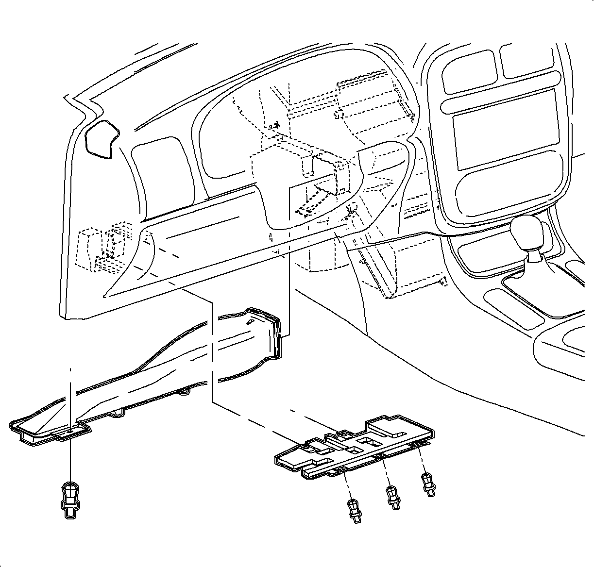
- Remove left side lower I/P closeout panel (hush
panel) push pin fasteners and remove panel.
- Remove left side lower heat duct assembly push pin fastener and remove
duct.
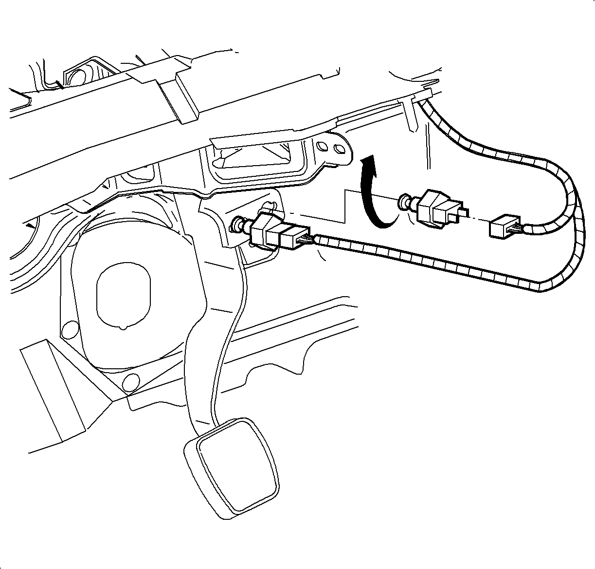
- Remove applicable switch from bracket by rotating
90 degrees.
Notice: The notch on the plunger will be fully visible when the plunger is fully extended.
Notice: If switch plunger separates from switch body, do not attempt to re-insert
plunger into switch body. Switch must be replaced.
Notice: Do not attempt to adjust switch more than three times. Multiple adjustments
of the switch will cause excessive wear on the adjustment mechanism within the switch.
If switch has been adjusted more than three times replace the switch.
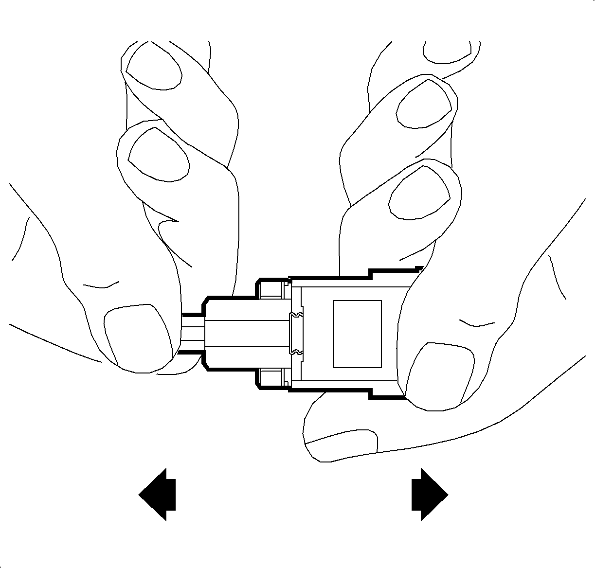
- Fully extend plunger from switch housing (may
require moderate force) to prepare switch for adjustment.
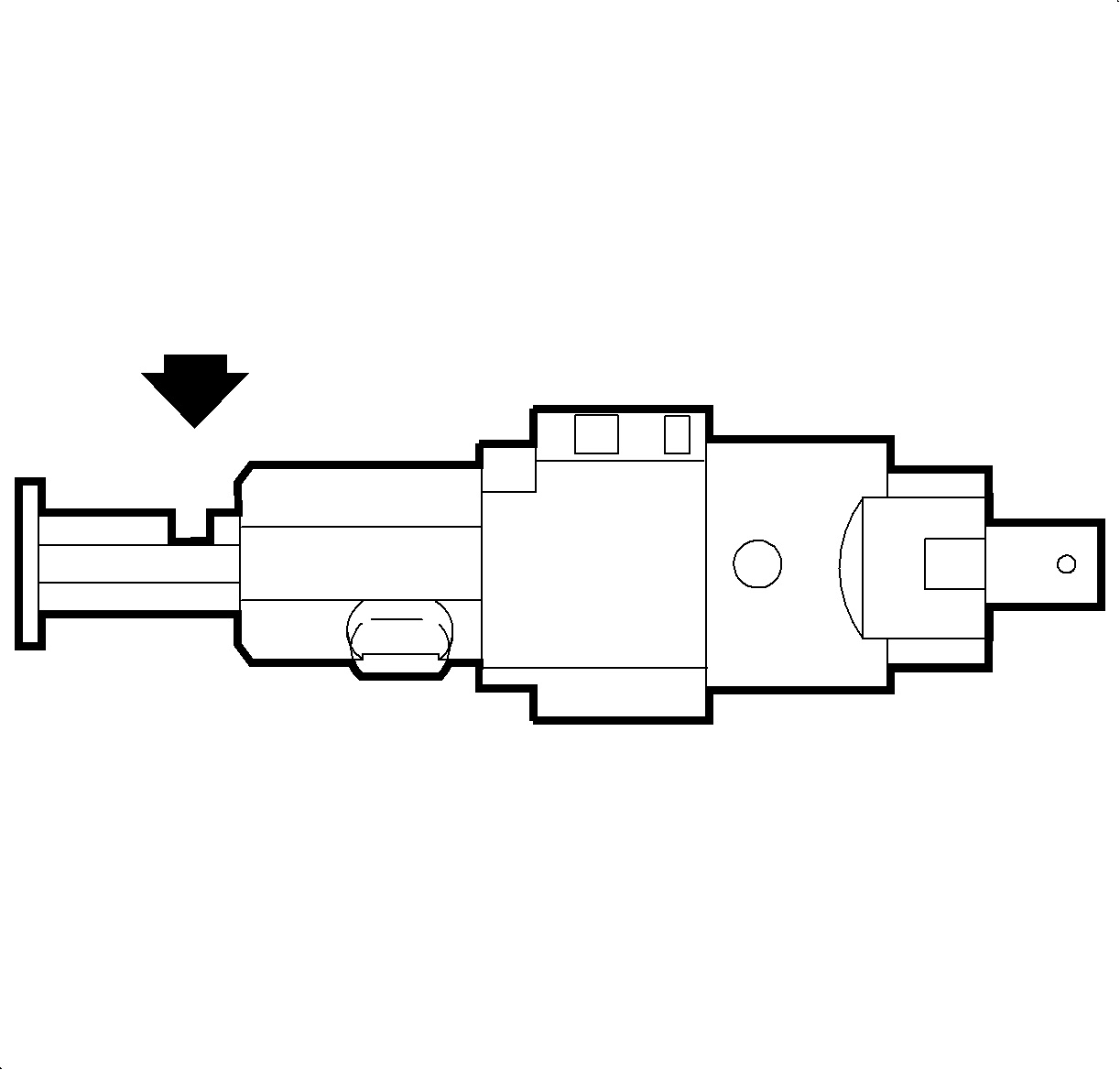
- 1st Design Brake Lamp Switch
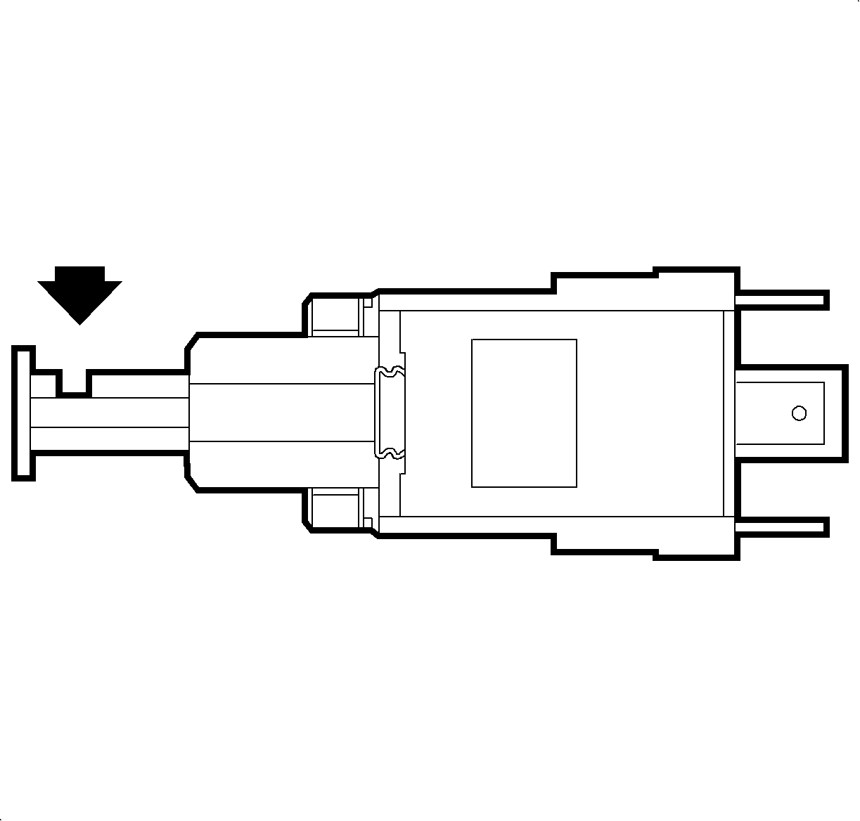
- Cruise/Brake and 2nd Design Brake Lamp witch

- Install applicable switch into bracket and rotate
90 degrees while holding brake pedal down.
- Adjust applicable switch by pulling up on brake or clutch pedal by hand
with moderate force.
Notice: Do not pull up on brake or clutch pedal with excessive force. Adjustment is
complete after 2 to 3 clicks are heard from the switch.
- Ensure that the brake lamps and cruise control function as designed.
| • | If either system does not function as designed, re-adjust the appropriate
switch using by procedure outlined in this bulletin. |
| • | If both systems function properly continue to next step. |

- Install left side lower heater duct and push
pin fastener.
- Install left side lower I/P closeout panel (push panel) and push pin fasteners.


