4T40E TRANSAXLE TORQUE CONVERTER INSPECTION AND TORQUE CONVERTER OR TRANSAXLE REPLACEMENT, IF NECESSARY

| Subject: | 4T40E TRANSAXLE TORQUE CONVERTER INSPECTION AND TORQUE CONVERTER OR TRANSAXLE REPLACEMENT, IF NECESSARY |
| Models: | 2001 SATURN L-SERIES VEHICLES EQUIPPED WITH 4T40E (RPO MN4) TRANSAXLES AND 4CYL (RPO L61) ENGINES ONLY |
ALL SATURN RETAILERS AND SERVICE PROVIDERS
Saturn has decided that certain 2001 L-Series Saturn vehicles may exhibit a condition in which the transaxle converter pump to stator bearing may prematurely fail due to a raised metal condition on the bearing surface on the inside of the pump cover. This may cause abnormal transaxle noise and may lead to premature failure.
To prevent the possibility of this condition occurring, Retailers will inspect the torque converter for certain production date codes, and, if necessary replace the transaxle
Vehicles Involved
Only selected 2001 model year L-Series Saturn vehicles within the following VIN range will require this campaign:
1Y536134 - 1Y550873
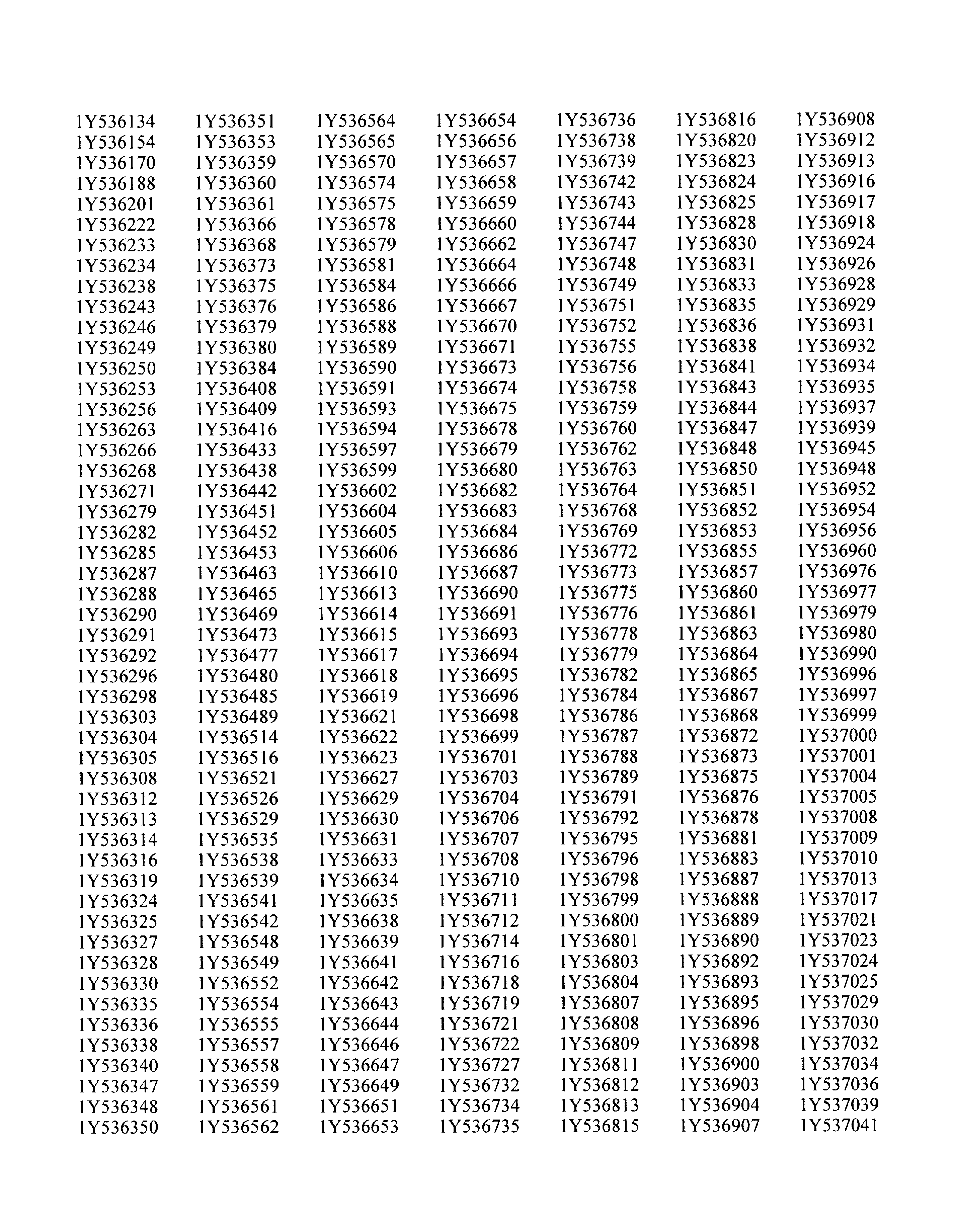
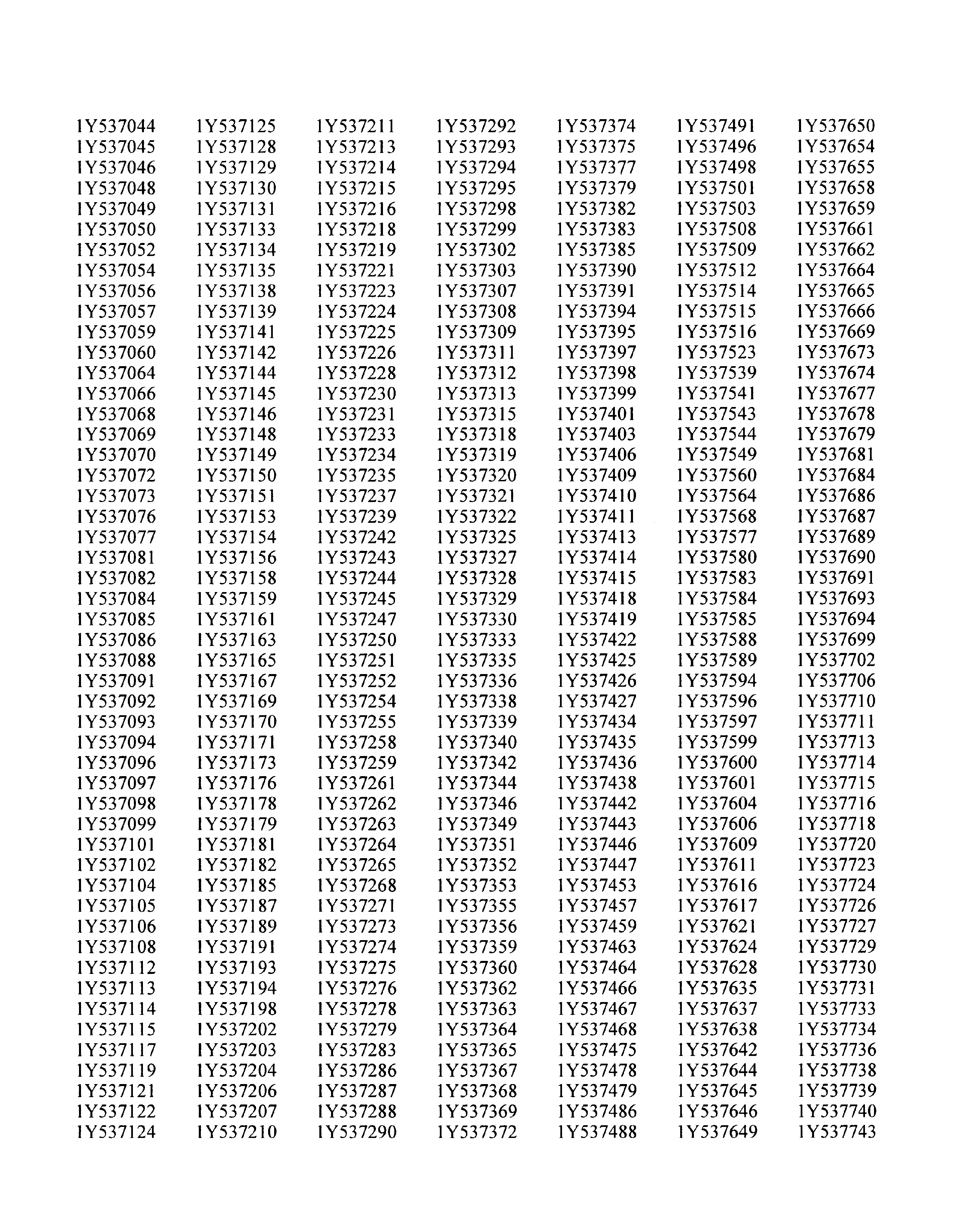
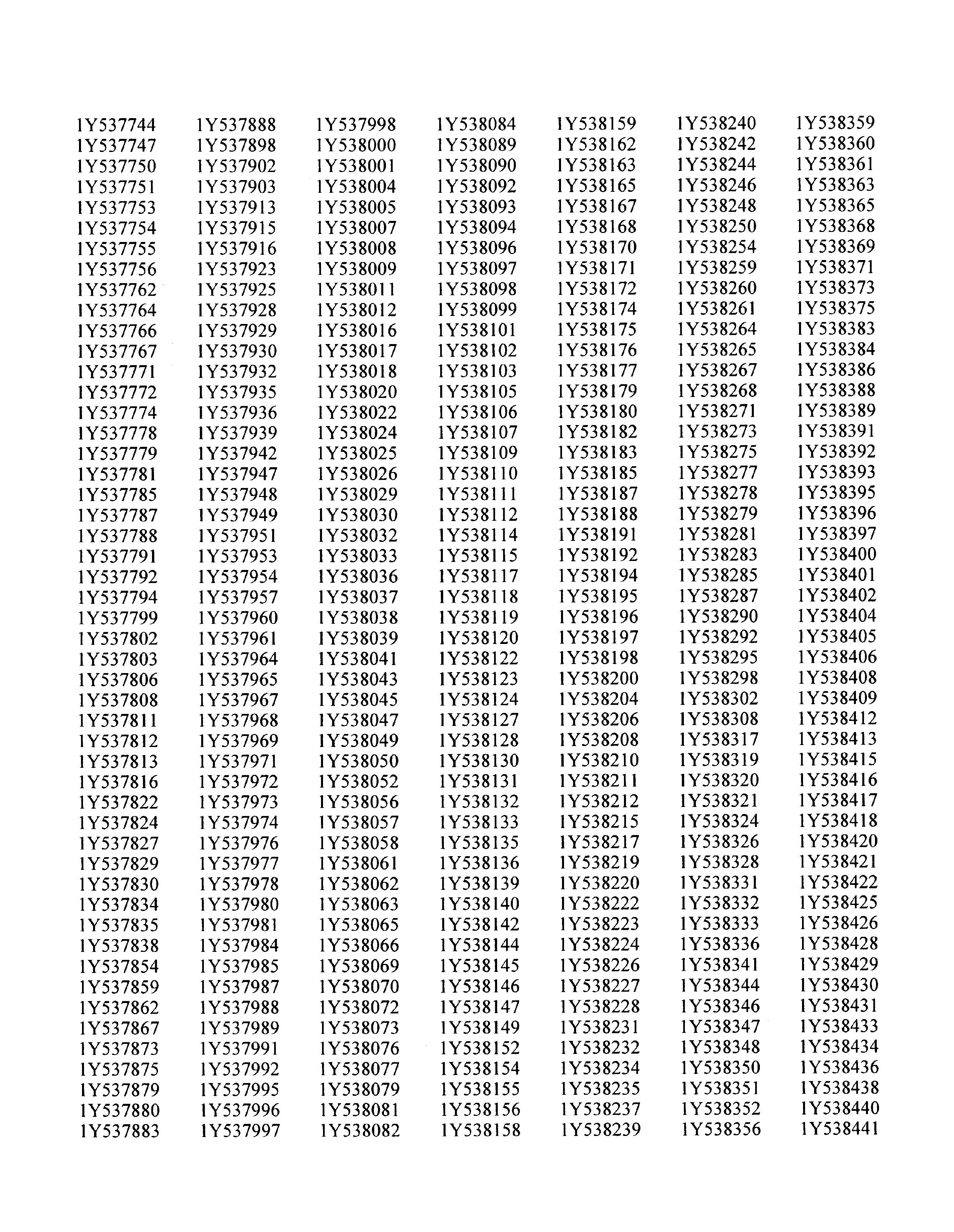
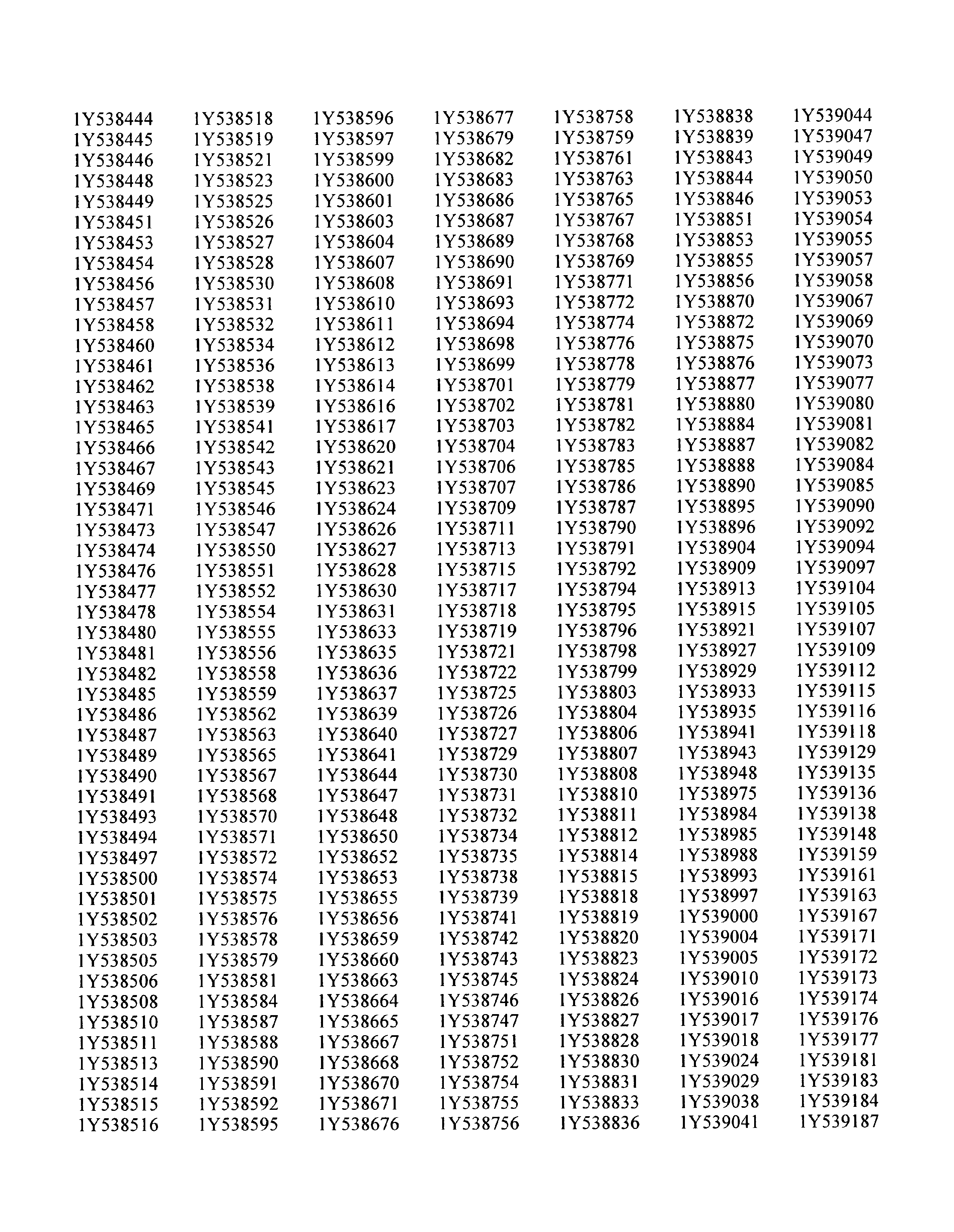
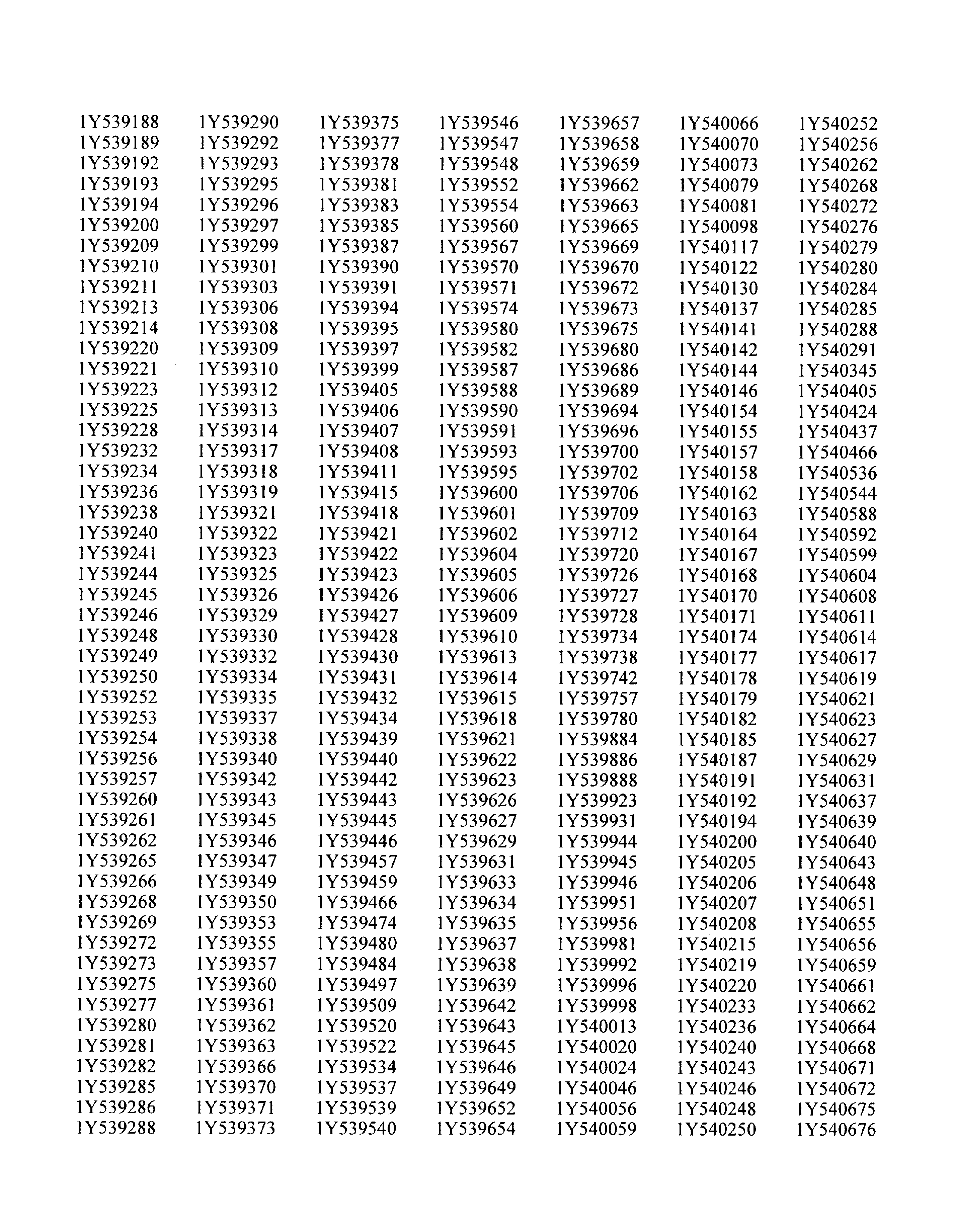
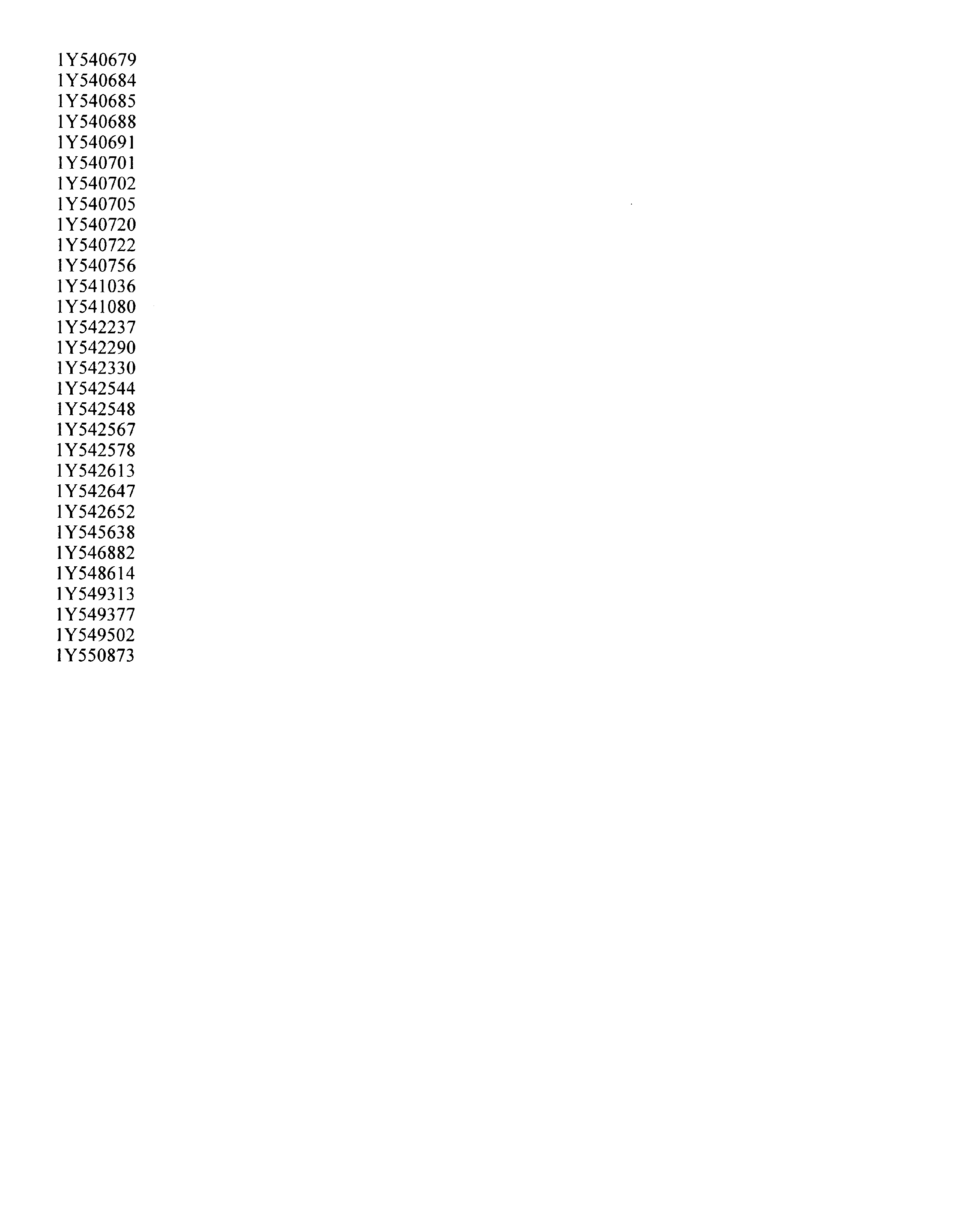
A VIN listing of the vehicles is included in this bulletin for your reference.
You must verify campaign involvement through your AS400 system. It is important to note that campaign claims will only be paid on involved vehicles.
Owner Notification
Owners of all involved vehicles will be notified of the campaign by Saturn. (Refer to the owner letter included in this bulletin.)
Facility VIN Listing
A list of vehicles assigned to you (Facility VIN Listing), which our records indicate were sold by or shipped to you, (or are located in close proximity to your facility) is enclosed.
This list contains
| • | Owner's name with address and telephone number |
| • | Complete vehicle identification number (VIN); and |
| • | VINs of vehicles, which according to Saturn records are in retail stock. |
The Facility VIN Listing (with owner information) is furnished to involved Retailers with the Product Campaign Bulletin. Although these vehicles are assigned to your facility, it is important to note that owners may elect to have their vehicle serviced at the Saturn Retail Facility of their choice.
Those Retailers not involved initially in this campaign will receive a message at the top of a blank Facility VIN Listing that states: NO VEHICLES ASSIGNED AT THIS TIME FOR CAMPAIGN 01-C-07.
These listings may contain owner names and addresses obtained from State Motor Vehicle Registration Records. The use of such motor vehicle registration data for any other purpose is a violation of the law in several states. Accordingly, you are urged to limit the use of this listing to the follow up necessary to complete this campaign. Those records updated with the California DMV registration information will have the following message printed adjacent to the appropriate VIN: "OWNER INFORMATION UPDATED BY CALIFORNIA DMV; PUBLICATION PROHIBITED."
Retailer Responsibility
All unsold vehicles in Retailers’ possession and subject to this campaign must be held at the retail facility and repaired per the service procedure of this campaign bulletin before owners take possession of these vehicles.
Retailers are to service all vehicles subject to this campaign at no charge to owners, regardless of mileage, age of vehicle, or ownership, from this time forward.
Owners of vehicles recently sold from your vehicle inventory are to be contacted by the Retailer and arrangements made to make the required correction according to the procedure contained in this bulletin.
In summary, whenever a vehicle subject to this campaign enters your vehicle inventory, or is in your retail facility for service in the future, please take the steps necessary to be sure the campaign correction has been made before selling or releasing the vehicle.
Transfer of Campaign Responsibility
Saturn vehicles that have been sold by you, which may be closer in proximity to another Saturn Retailer, may still appear on your Facility VIN Listing. If either you or the vehicle owner determines that it is more desirable for a vehicle on your Facility VIN Listing to be serviced by another Saturn Retailer, or if the customer’s address has recently changed, campaign responsibility may be transferred by completing the following:
| • | Submit a Campaign Vehicle Action Report to your Customer Assistance Manager (CAM) at the Saturn Customer Assistance Center. |
| OR |
| • | Submit an update in owner information to the Saturn Owner of Record system, via SERVICELINE XL, for Saturn Customer Assistance Center review and approval. |
A copy of the Campaign Vehicle Action Report is included for your reference. Additional copies can be ordered from Saturn Publications (1-800-828-2112, prompt 3, Item # S0397050). All changes to campaign responsibility will be reflected in your next Unfixed VIN Report.
All other changes in vehicle status (e.g., scrapped, stolen, etc.) are to be made in accordance with section 4.4.3 of the Retailer Service Reference Guide, "Notifying Saturn of Vehicle Status Change."
Parts Information
Once the vehicle has been inspected and it has been verified that a part is required, please order the appropriate parts from SSPO.
Part Number | Description | Quantity Required Per Vehicle |
|---|---|---|
24211330 OR 24218105 | Converter Asm-Torq Transaxle Asm-Auto | 1 |
08677453 | Seal-Turb Shf | 1* |
90468617 | Nut-Frt Susp | 10 |
11095961 | Bolt/Screw-Frt Susp Supt | 6 |
11097811 | Bolt/Screw-Frt Susp Frm | 4 |
11099501 | Bolt/Screw-S/Gr | 2 |
11094487 | Nut-S/Gr | 2 |
Incidental Parts: The replacement of the torque converter and/or transaxle may require the use of some incidental parts. These parts are as follows:
Part Number | Description | Quantity Required Per Vehicle |
|---|---|---|
21019223 | Fluid-A/Trans | 2 Qts * |
*Only required with torque converter replacement.
Disposition of Replaced Parts
Retailers are to fill out the Yellow Core Return Tag for each replacement transaxle and torque converter. If the Yellow Core Return Tag is not included, please use a blank tag. If you require additional tags, please contact your Parts Support Analyst. Return the transaxle and/or torque converter, along with the Yellow Core Return Tag, using the existing core return process. If you have any questions on how to process a core return, please refer to your Parts Policies and Procedures Manual, or contact your PSA. Any remaining parts should be replaced and scrapped in a manner that ensures that they cannot be reused, remanufactured, or otherwise entered into the stream of commerce in the future.
Suggestions for Ensuring Customer Satisfaction
As you know, Saturn’s success hinges upon our ability to execute superior customer support throughout the ownership experience, especially when important corrective actions such as this are required.
It is imperative that every effort is made to accommodate the affected owners. Additionally, priority should be given to customer vehicles over retail inventory vehicles. If you have any questions, please coordinate with the Saturn Customer Assistance Center to help ensure customer satisfaction.
Primary Torque Converter Inspection Procedure (On-Vehicle)
- Remove the inspection plug located on the top of the transaxle case directly over the torque converter.
- Disable engine spark and injector pulse by disconnecting the electrical connector from the ignition module located on the cam cover.
- Have an assistant "bump" the engine over by cycling the ignition key from RUN to START repeatedly to slowly rotate the converter. Make sure the torque converter makes at least one full revolution in order to see all paint markings
- As the engine bumps over slowly, inspect the torque converter for paint markings. The markings may be on the transaxle side of the converter and better seen from the left side (toward left front wheel) of the inspection hole.
- A Green paint streak indicates that the converter may need replacement. All converters with a Green paint streak will require removal of the transaxle and further inspection to determine if the converter or transaxle needs replacement. In addition, a converter with no paint markings will also require further inspection. Therefore:
- Install the inspection plug in the transaxle case and reconnect the electrical connector to the ignition module.
- Affix Campaign Completion Label (Campaign number 01-C-07) on a clean and dry surface of radiator core support, in an area clearly visible when hood is raised. (For more information, refer to "Campaign Completion Label" in this bulletin.)
Important: The purpose of this primary inspection is to determine if the transaxle needs to be removed in order to perform further inspections. In this primary inspection, you will be looking for a spray paint streak on the circumference of the torque converter, which the manufacturer used in their identification process.
| • | If a Green paint stripe is present, or no paint mark of Any Color is visible, the transaxle must be removed for further inspection. Proceed to "Transaxle Removal" procedure in this bulletin to remove the transaxle and torque converter for further inspection. Once transaxle is removed proceed to "Torque Converter Inspection Procedure (Off-Vehicle)" for secondary inspection procedure. |
| • | Multiple other colors are likely to be present, and except for Green , are considered acceptable. If a color(s) other than Green is present, and no Green paint stripe is found, continue to step 6. |
Important: Do not cover any existing underhood labels when affixing Campaign Completion Label.
Torque Converter Inspection Procedure (Off-Vehicle)
Important: If the primary torque converter inspection procedure (on-vehicle), performed earlier, revealed either Green paint or no paint markings on the torque converter, the transaxle must be removed to permit a (off-vehicle) inspection and possible additional repairs. Transaxle removal procedures are contained in the following section. Once removal of the transaxle has been completed, it will then be necessary to identify and interpret the date and time ink stamping on the flex plate side of the torque converter (see arrow in illustration below).
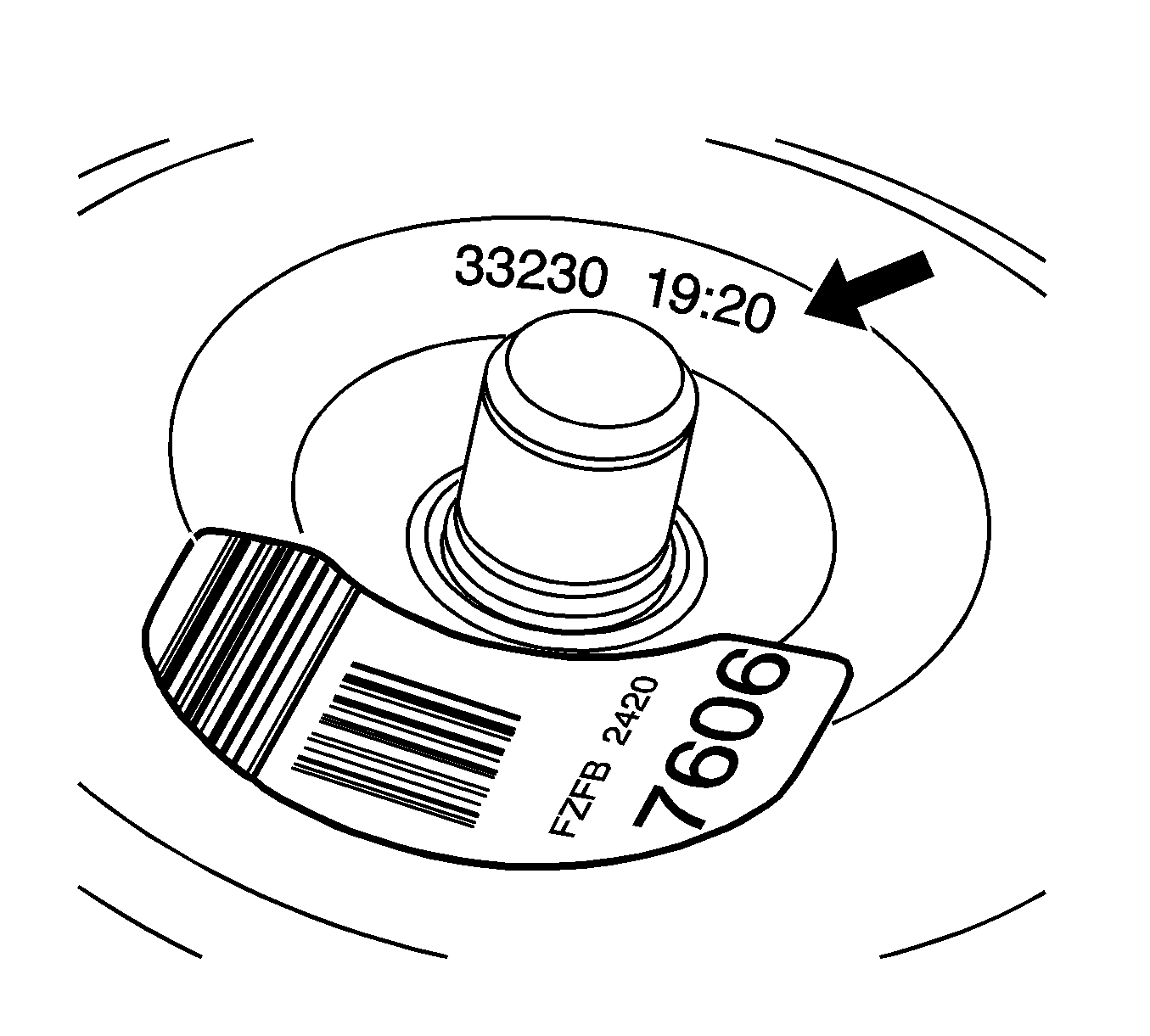
The date and time ink stamp contains nine (9) digits as illustrated below. The 1st through 3rd digits of the code indicate the Julian date of production (the numerical day of the year); the 4th digit indicates the specific production line the part ran on. The 5th digit indicates the calendar year (0=2000). The 6th - 9th digits indicate the part production time in hours and minutes using the 24-hour military clock.
33230 | 19:20 |
Date | Time |
Stamp | Stamp |
- Remove transaxle assembly. Refer to "Transaxle Removal" procedure in this bulletin to remove transaxle.
- Inspect date code and time stamp on torque converter for one of the following conditions.
Important: Only torque converters stamped with date codes 332 and 333 are affected by this campaign. All torque converters with the 332 date code are affected. Additionally, torque converters with the 333 date code are affected only if the time stamp is before or equal to 10:00.
| • | If torque converter has a 332 date code with any time stamp, or the 333 date code with time stamp before or equal to 10:00 and the vehicle has 100 miles or less , then replace the torque converter and turbine shaft O-ring. Continue to steps below for replacement. |
| 1. | Remove torque converter from transaxle. |
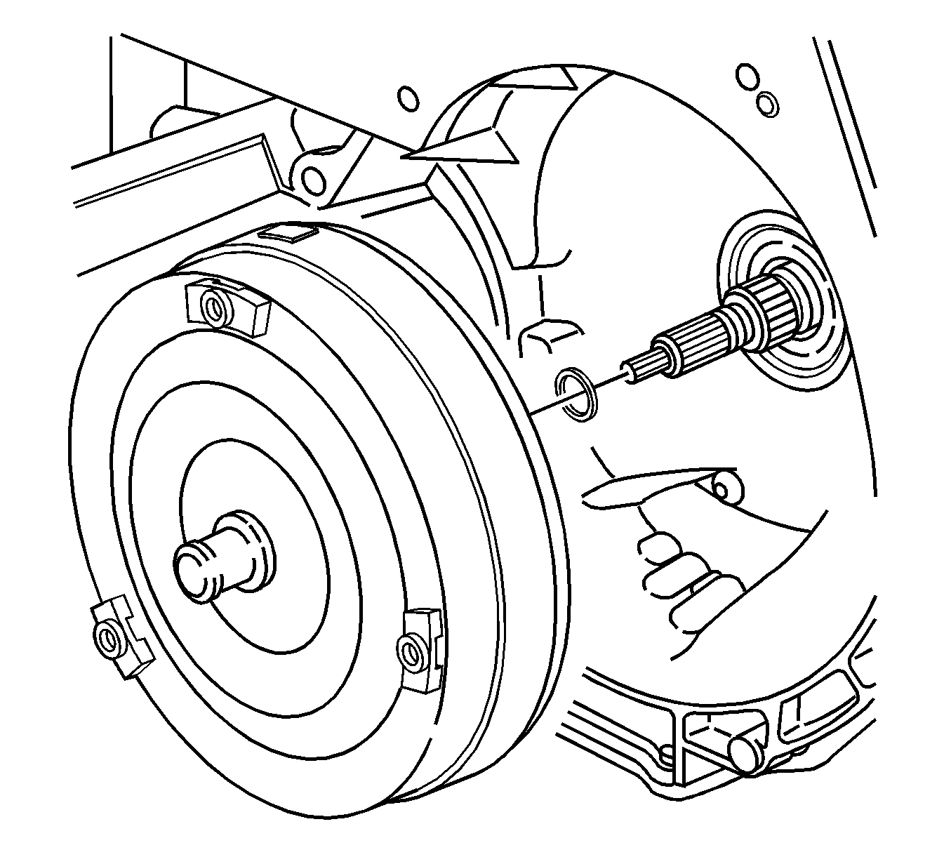
| 2. | Remove turbine shaft O-ring from end of turbine shaft. |
| 3. | Refer to step 1 of "Transaxle Installation" procedure in this bulletin for torque converter and transaxle installation procedure. |
| • | If the torque converter has either the 332 date code or the 333 date code with time stamp before or equal to 10:00 and the vehicle has 100 miles or more , then replace the transaxle assembly and flush the transaxle cooler lines. Refer to step 3 of "Transaxle Installation" procedure in this bulletin for transaxle installation procedure. |
| Important: A replacement transaxle comes with a torque converter support shipping bracket that must be removed and transferred to the transaxle being returned. |
| • | If torque converter does not have one of the suspect date codes, no repairs are needed. Reinstall transaxle assembly back into vehicle. Refer to step 4 of "Transaxle Installation" procedure in this bulletin for transaxle installation procedure. |
Transaxle Removal Procedure
Tools Required
| • | J43405 Engine Support Fixture Adapter |
| • | J43628 Frame Alignment Tool |
| • | J44014 Torque Converter Bolt Socket |
| • | SA9105E Engine Support Bar Assembly |
| • | J35944-440 Cooler Flusher Adapter |
| • | SA9165T Oil Line Cooler Flusher |
- Position vehicle on hoist.
- Remove battery.
- Disconnect battery feed to underhood fuse block.
- Disconnect coolant hose from underhood fuse block cover.
- Release retaining tabs on underhood fuse block cover and remove.
- Release retaining tabs (2) on underhood fuse block and roll fuse block back (1) to access electrical connectors.
- Remove following connectors from under hood fuse block:
- Lift fuse block off case.
- Remove harnesses from underhood fuse block case by releasing retaining tabs on the bottom of the hard shell grommets.
- Remove underhood fuse block case fastener, and remove case from battery tray.
- Remove battery tray fasteners and battery tray.
- Remove clamp from A.I.R. hose behind the cooling fan.
- Separate the A.I.R. tube from the hose and push the tube back towards the transaxle.
- Remove the hose clip holding the two power steering lines together.
- Disconnect control cable from transaxle range switch lever with a screwdriver.
- Remove control cable bracket from rear powertrain mount. Tie cable and bracket to dash panel.
- Remove transaxle electrical connector and ground wire from transaxle.
- Remove remaining wiring harness attachments from transaxle.
- Remove transaxle range switch electrical connectors.
- Remove upper engine-to-transaxle mounting bolts.
- Disconnect output speed sensor electrical connector. Remove harness from mounting stud.
- Install the Engine Support Bar Assembly SA9105E with Engine Support Fixture Adapter J43405 as shown.
- Remove the rear transaxle mount through bolt, and transaxle mount to frame bolt.
- Fasten the radiator to the upper radiator support.
- Raise the vehicle.
- Remove the front wheel and tire assemblies.
- Remove the right front lower splash shield.
- Remove the left front wheel liner push pin from frame.
- Disconnect the rear O2 sensor connection, and remove harness from frame at attachment points.
- Remove the front transaxle mount through bolt.
- Remove the remaining rear transaxle mount-to-frame bolts.
- Remove the steering gear-to-frame assembly bolts.
- Remove the steering gear heat shield.
- Using the mechanics wire, secure the steering gear assembly to body of vehicle.
- Remove the stabilizer bar links from strut assembly.
- Remove the lower ball stud bolt and separate ball stud from steering knuckle assembly.
- Remove the suspension support assemblies.
- Remove the suspension support cage nuts from body. Discard the cage nuts and support bolts, as new nuts and bolts must be used for assembly.
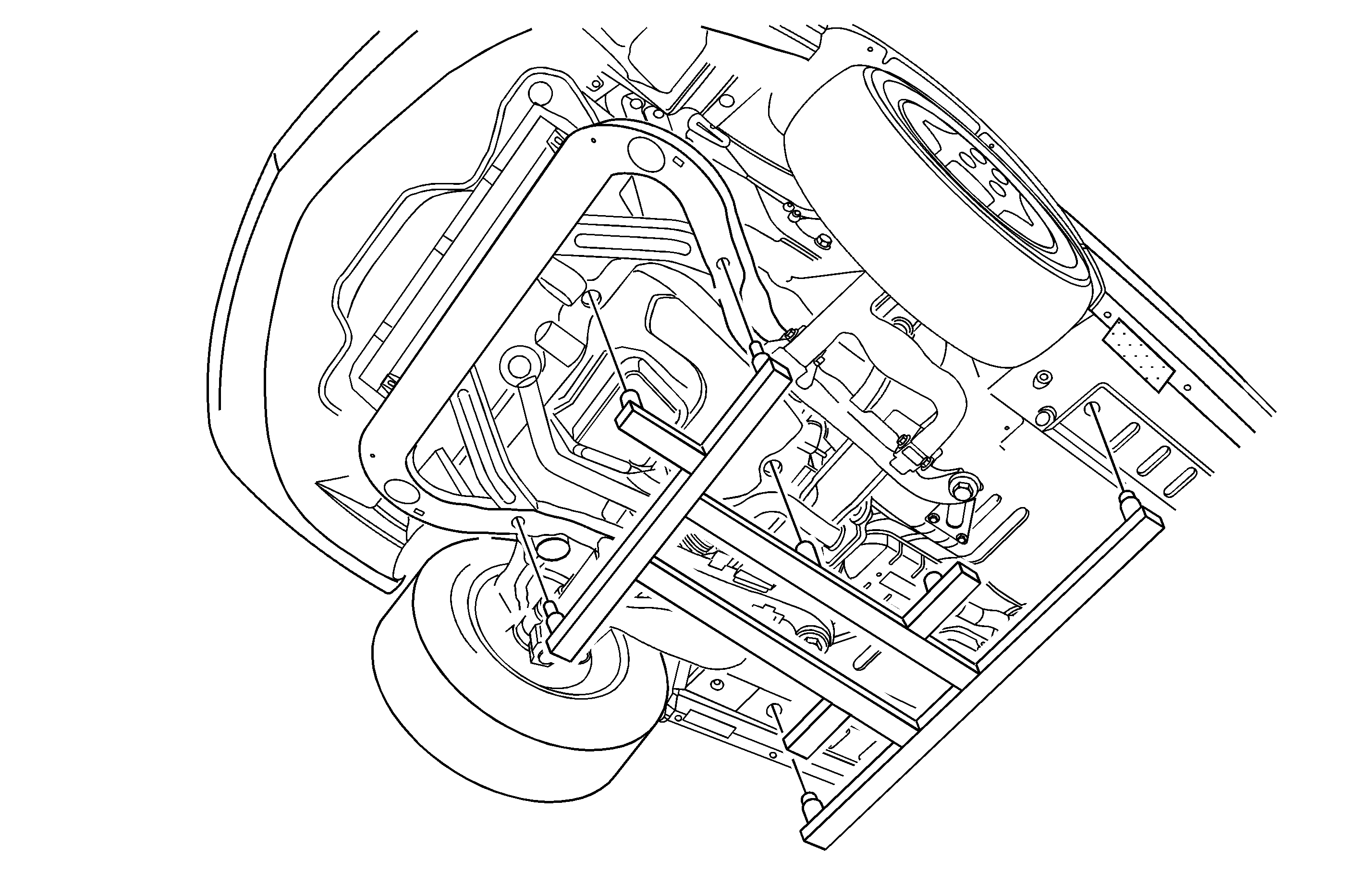
- Using the powertrain lifting table and the Frame Alignment Tool J43628, support frame assembly.
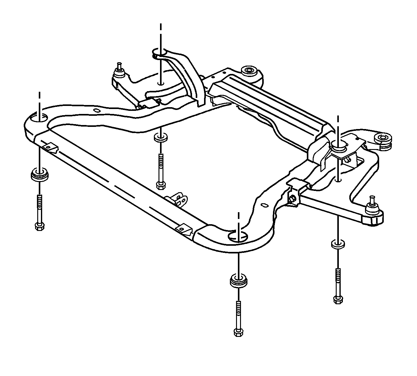
- Remove the remaining frame-to-body attachment fasteners.
- Carefully the lower frame assembly from vehicle.
- Remove the frame assembly cage nuts from body. Discard the cage nuts and frame bolts as new nuts and bolts must be used for assembly.
- Use a pry bar to remove axle shafts from transaxle. Leave axle shafts in steering knuckles and secure axle shafts up and out of way of transaxle removal path.
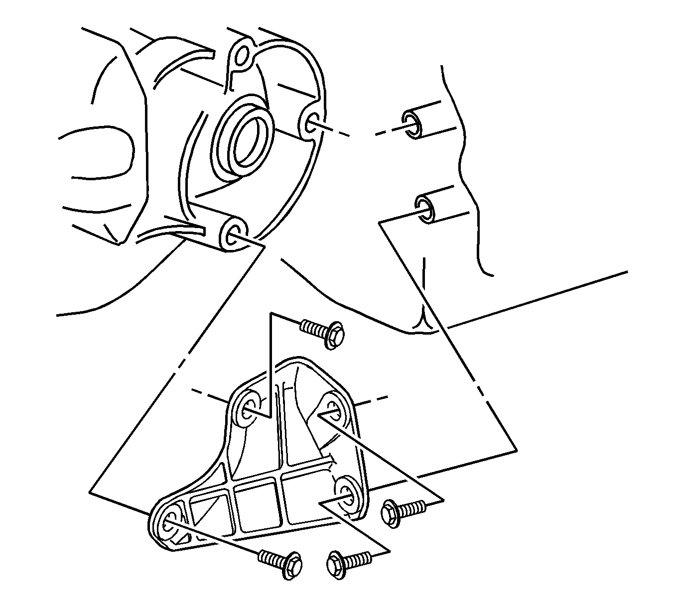
- Remove engine-to-transaxle bracket.
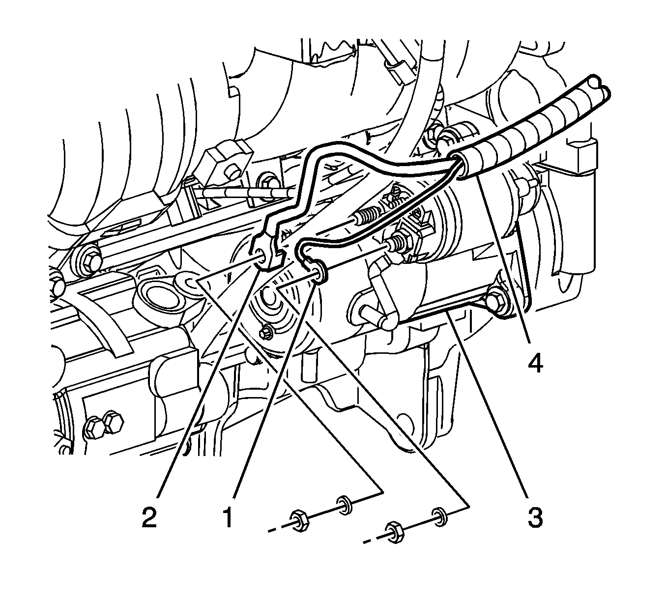
- Remove the starter solenoid electrical connections.
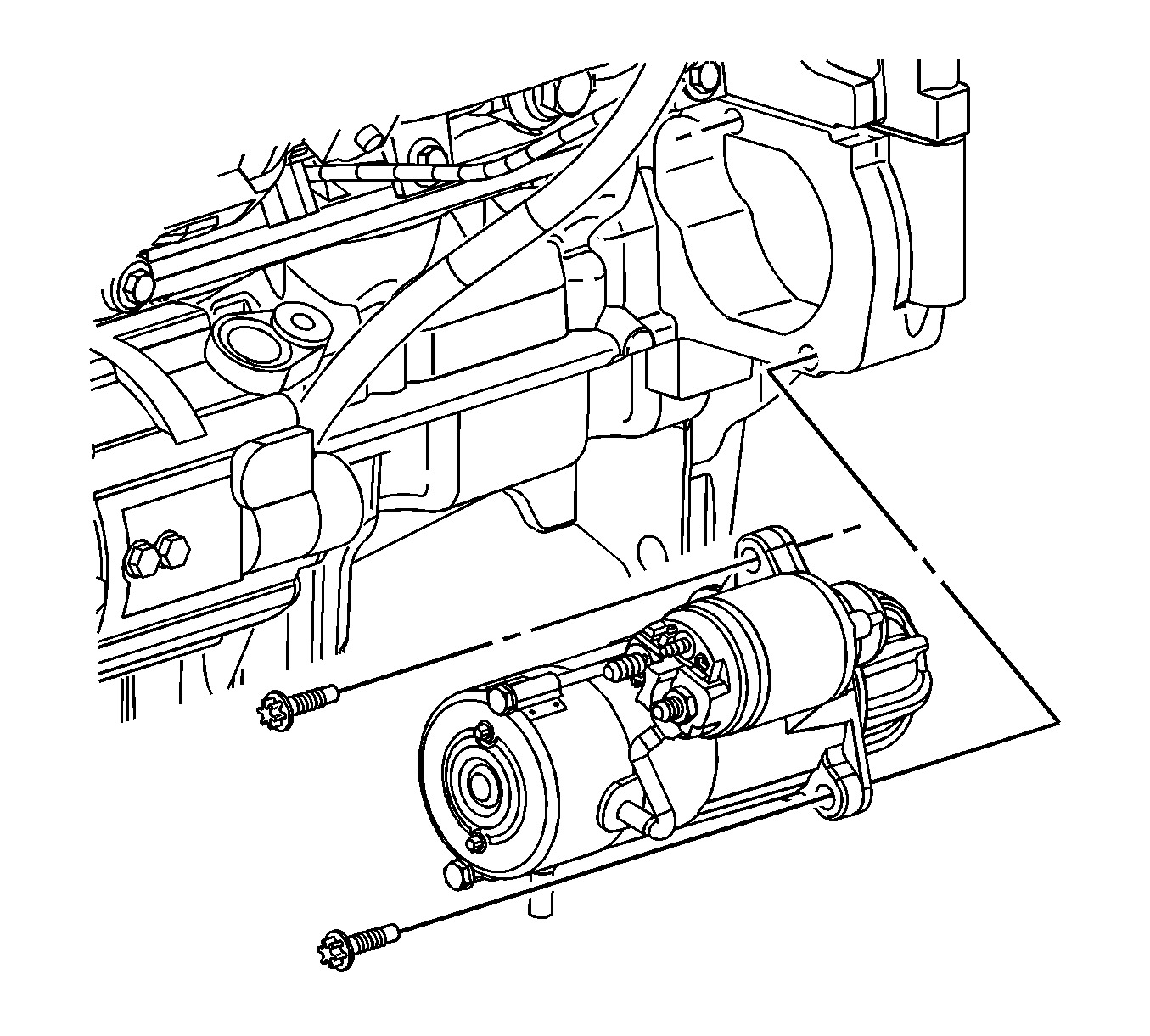
- Remove the starter motor.
- Use the Torque Converter Bolt Socket J 44014 to remove flex plate to torque converter bolts through starter opening in engine block.
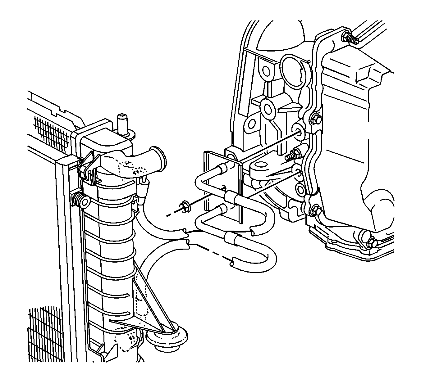
- Remove the transaxle oil cooler line assembly from transaxle.
- Remove the lower two engine-to-transaxle mounting bolts.
- Lower the vehicle.
- Mark the position of and remove the left transaxle mount bolts.
- Raise the vehicle.
- Slide the hydraulic lift table under transaxle.
- Lower the vehicle slowly until the transaxle is on the hydraulic lift table. Place a wood block between the barrel of transaxle and the surface of table.
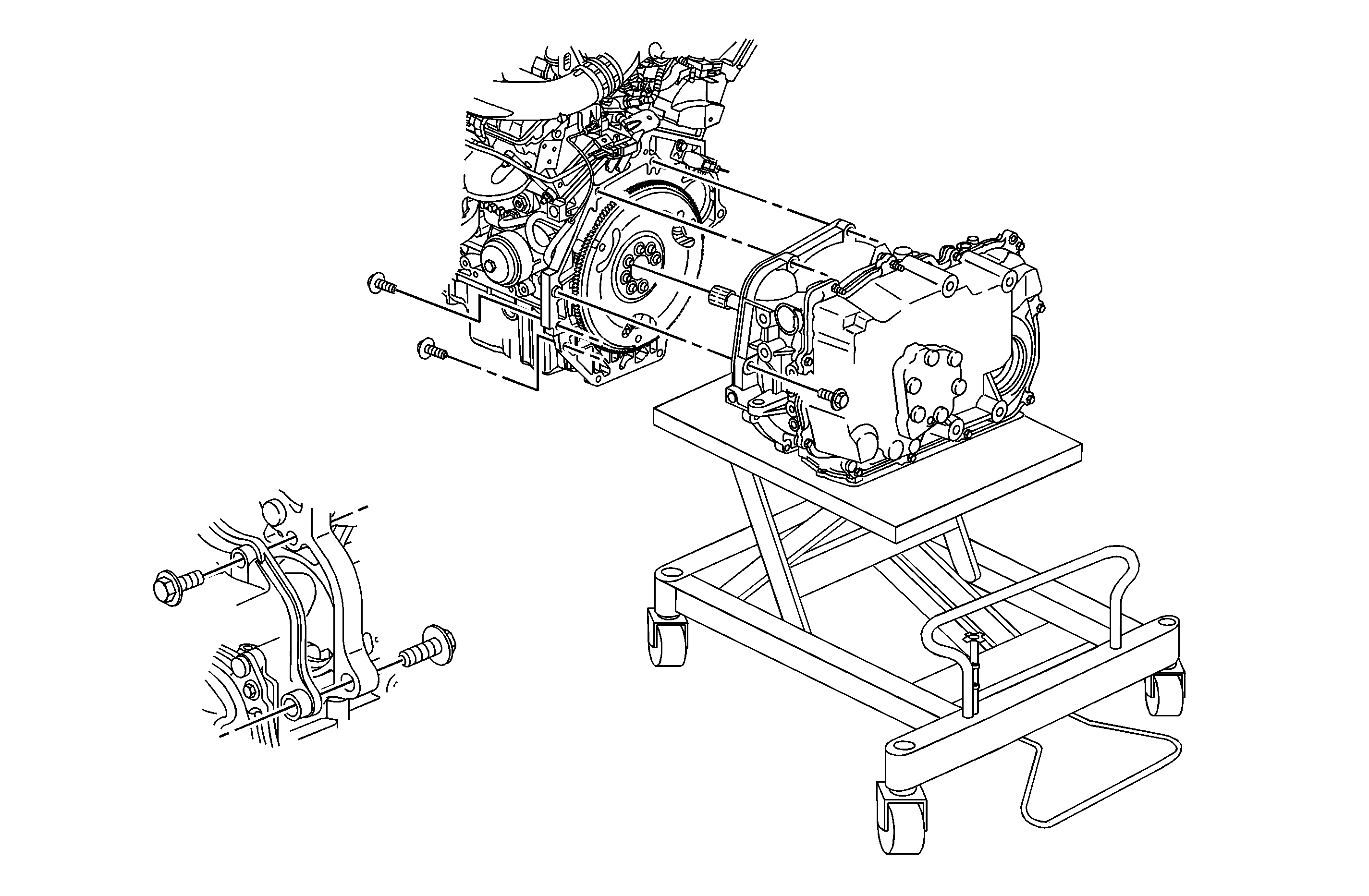
- Remove remaining engine-to-transaxle mounting bolts. There are a total of seven bolts retaining the transaxle to the engine.
- Slide the transaxle away from the engine assembly and raise the vehicle away from the transaxle. (L81 shown, L61 similar.)
- Inspect the torque converter for date code and time stamp. Refer to "Torque Converter Inspection (Off-Vehicle)" procedure at the beginning of this bulletin.
Caution: Make sure vehicle is properly supported and squarely positioned on the hoist. To help avoid personal injury when a vehicle is on a hoist, provide additional support for the vehicle on the opposite end from which components are being removed.
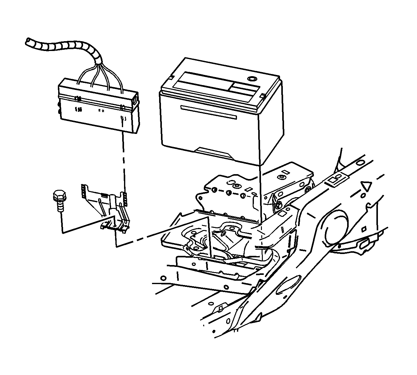
| 2.1. | Disconnect battery cables (negative first, positive second). |
| 2.2. | Move fan control module. Leave wiring connected, lift module up and away from bracket, and position out of the way. |
| 2.3. | Remove battery hold-down bracket. |
| 2.4. | Remove battery. |
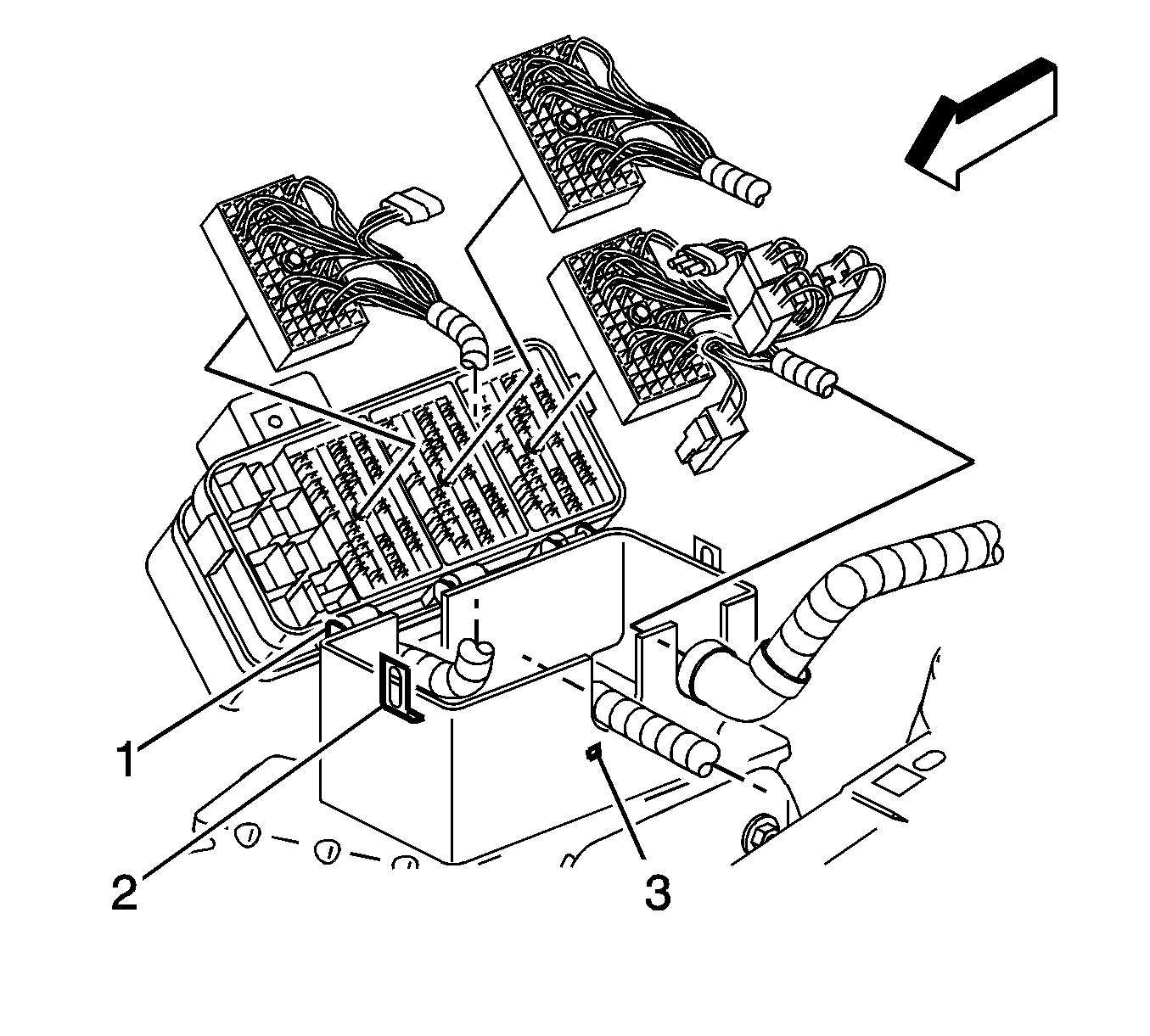
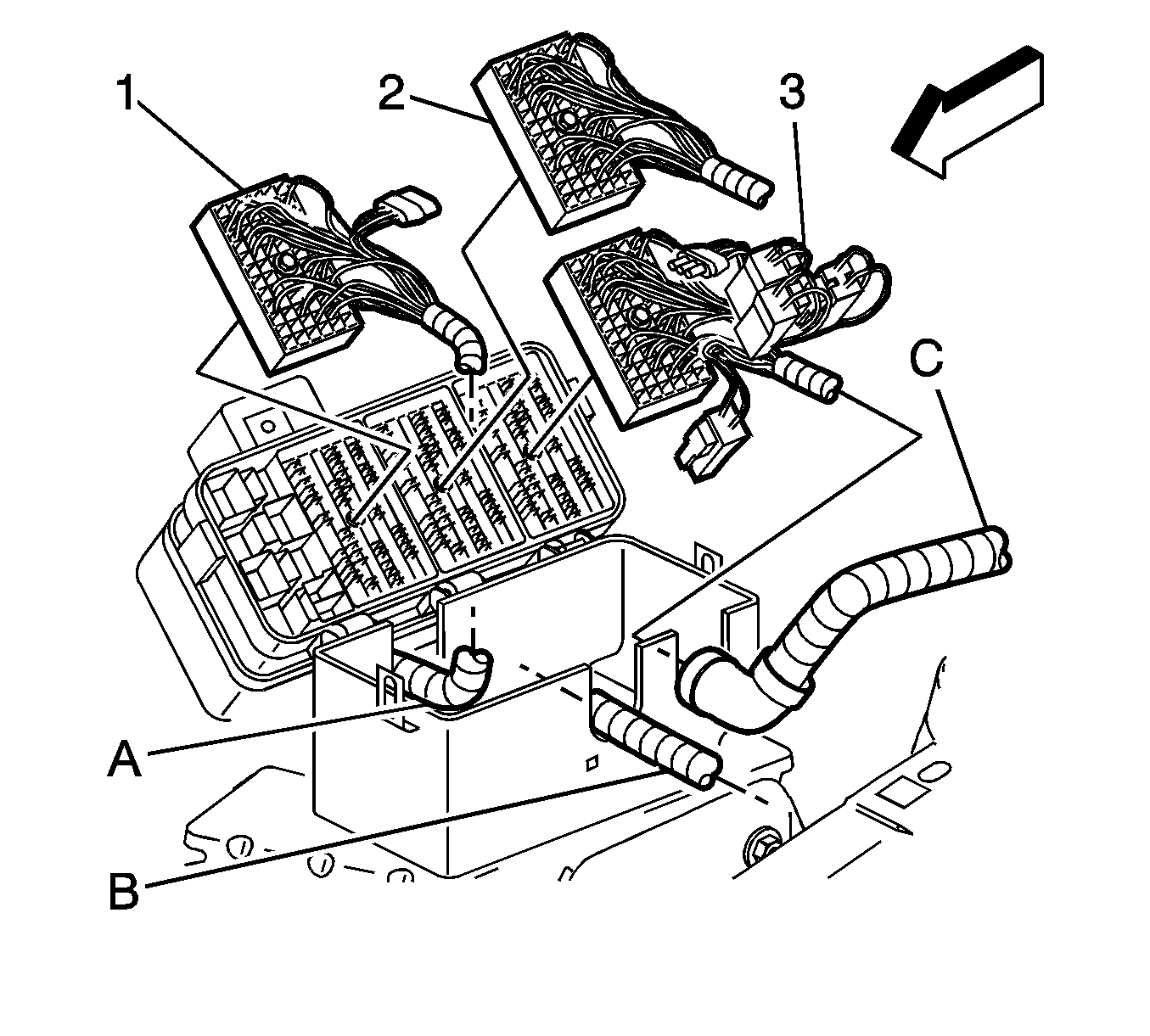
| • | Engine 68 way (1) |
| • | Forward Lamp 68 way (2) |
| • | I/P 68 way (3) |
| • | Forward Lamp 2 way (White) (4) |
| • | I/P 2 way (Black) (5) |
| • | I/P 2 way (Green) (6) |
| • | I/P 2 way (Brown) (7) |
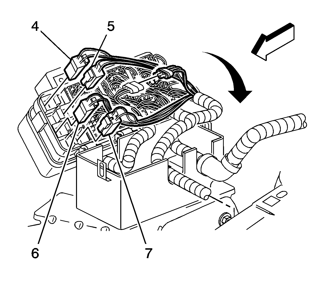
Important: There are two tabs that hold the hard shell grommets in place at the bottom of the grommet. Disengage tabs to remove grommet from case.
| • | Engine |
| • | Forward Lamp |
| • | Instrument Panel (I/P) |
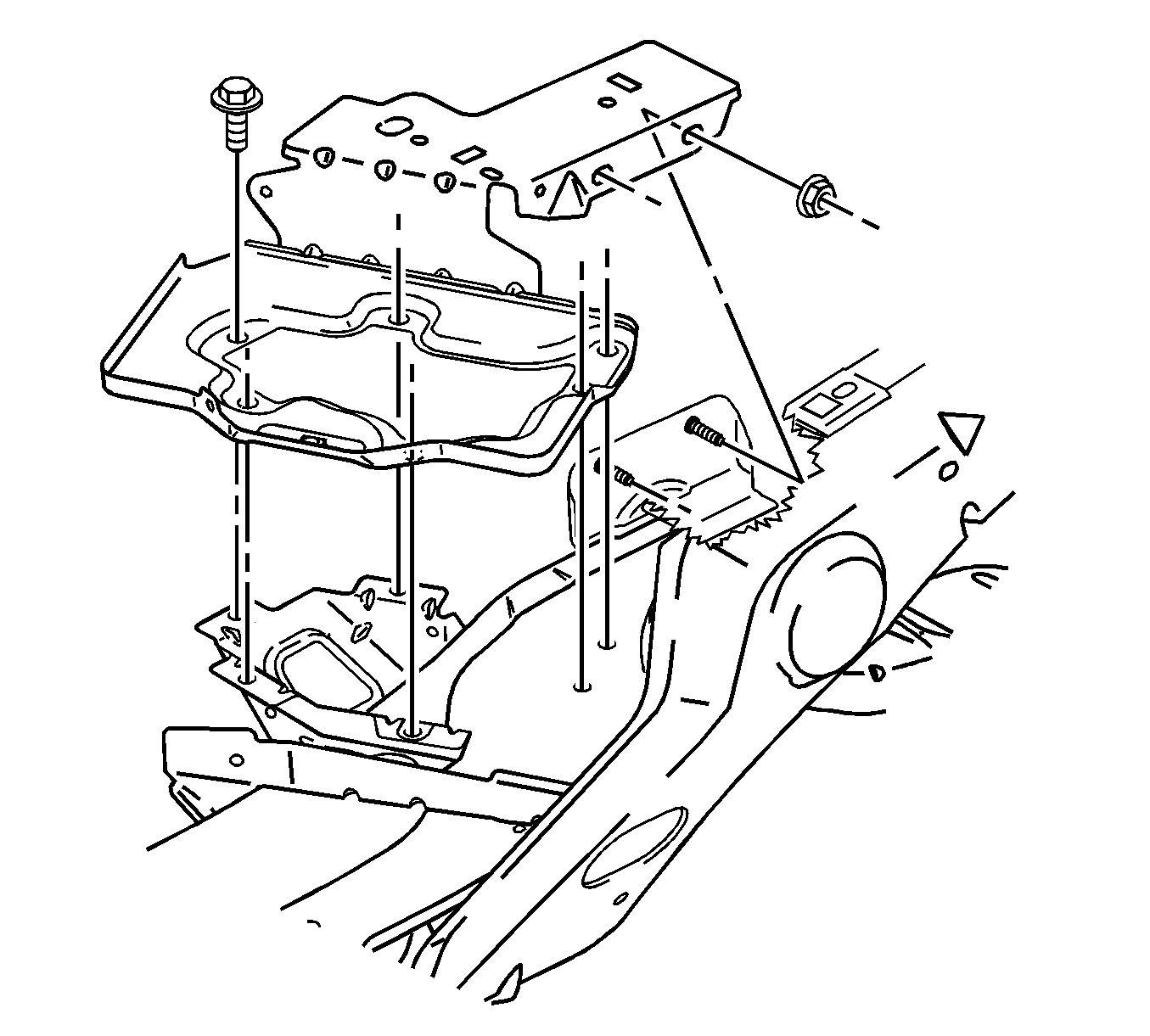
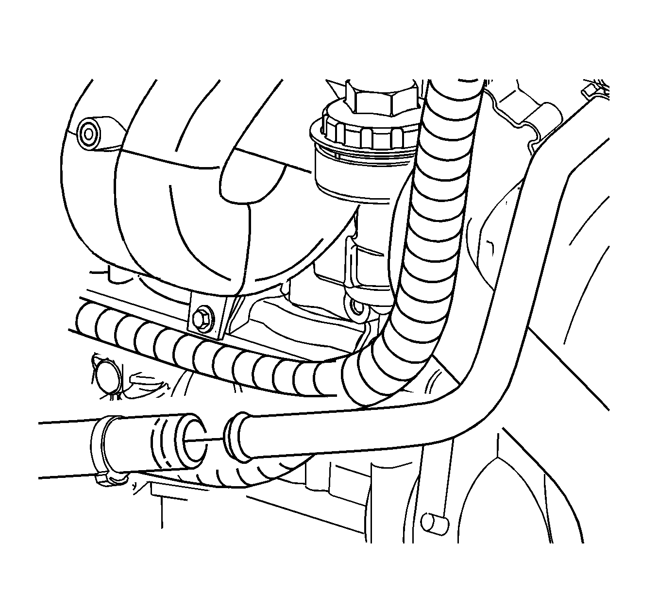
Important: Note the original position of the A.I.R. components.
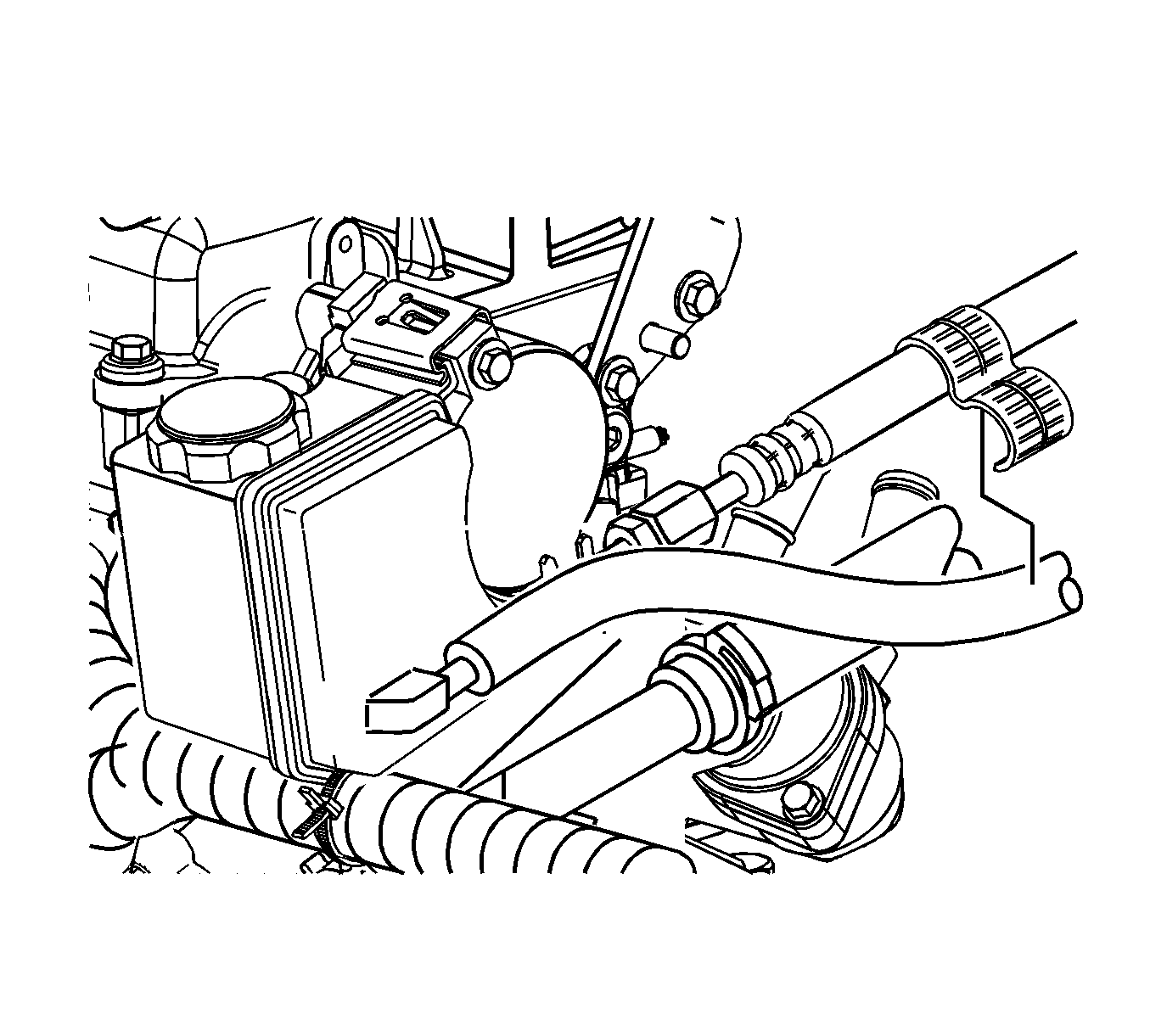
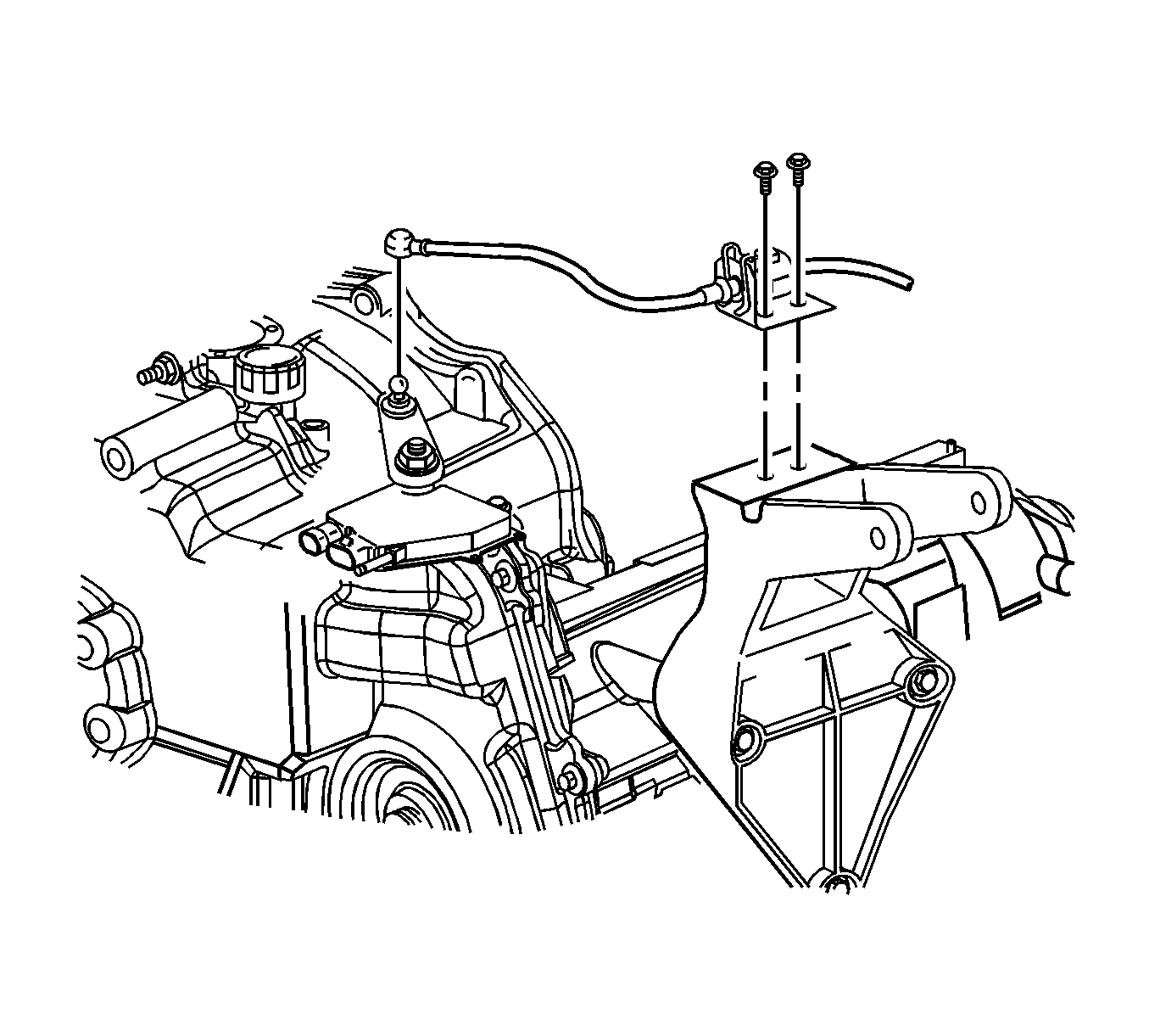
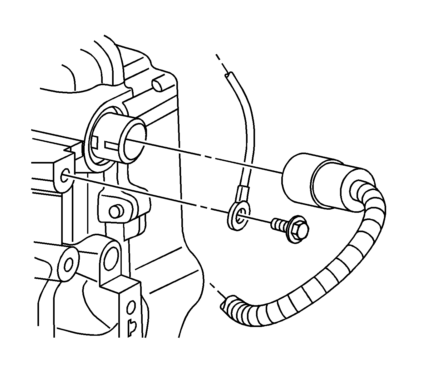
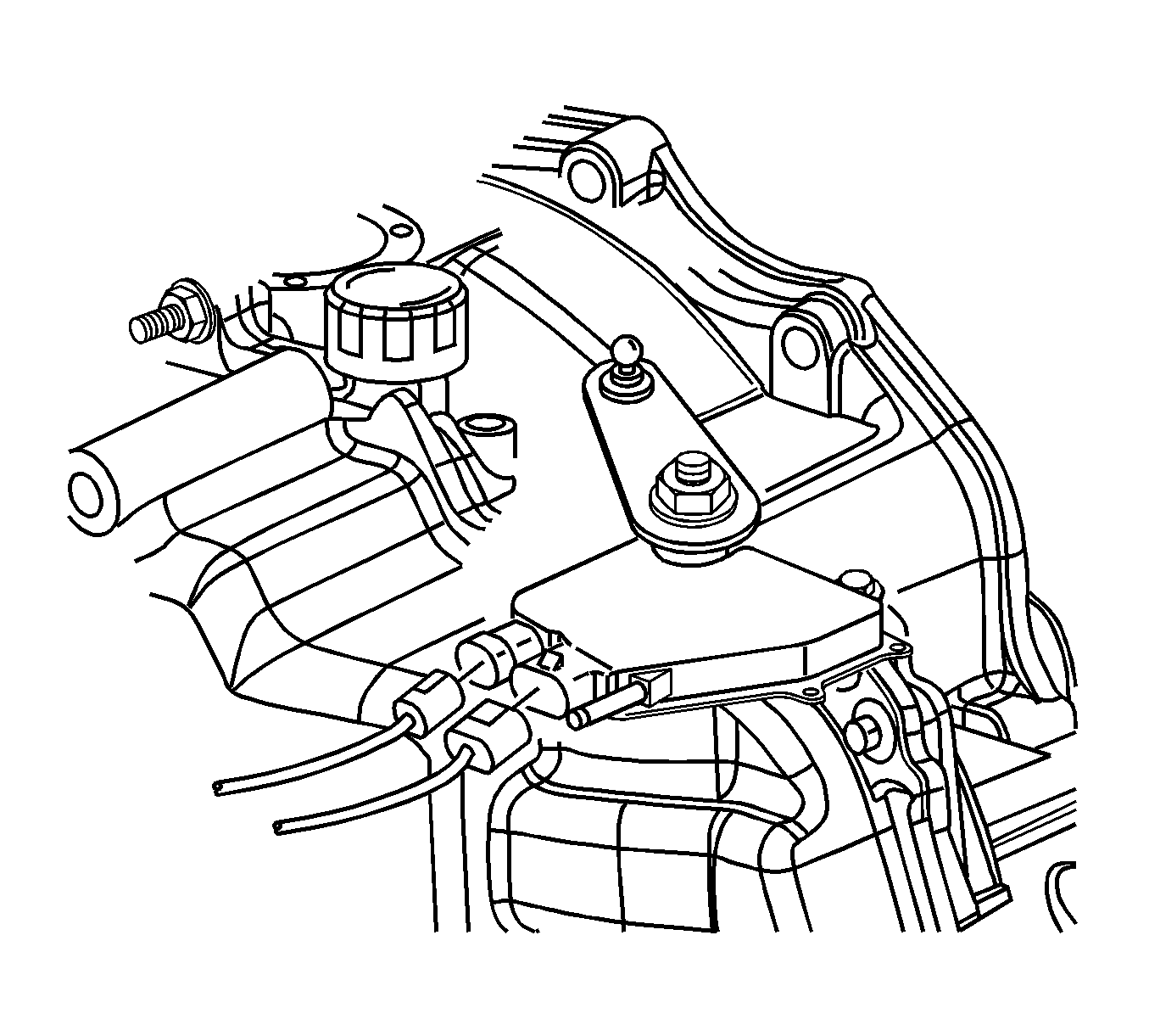
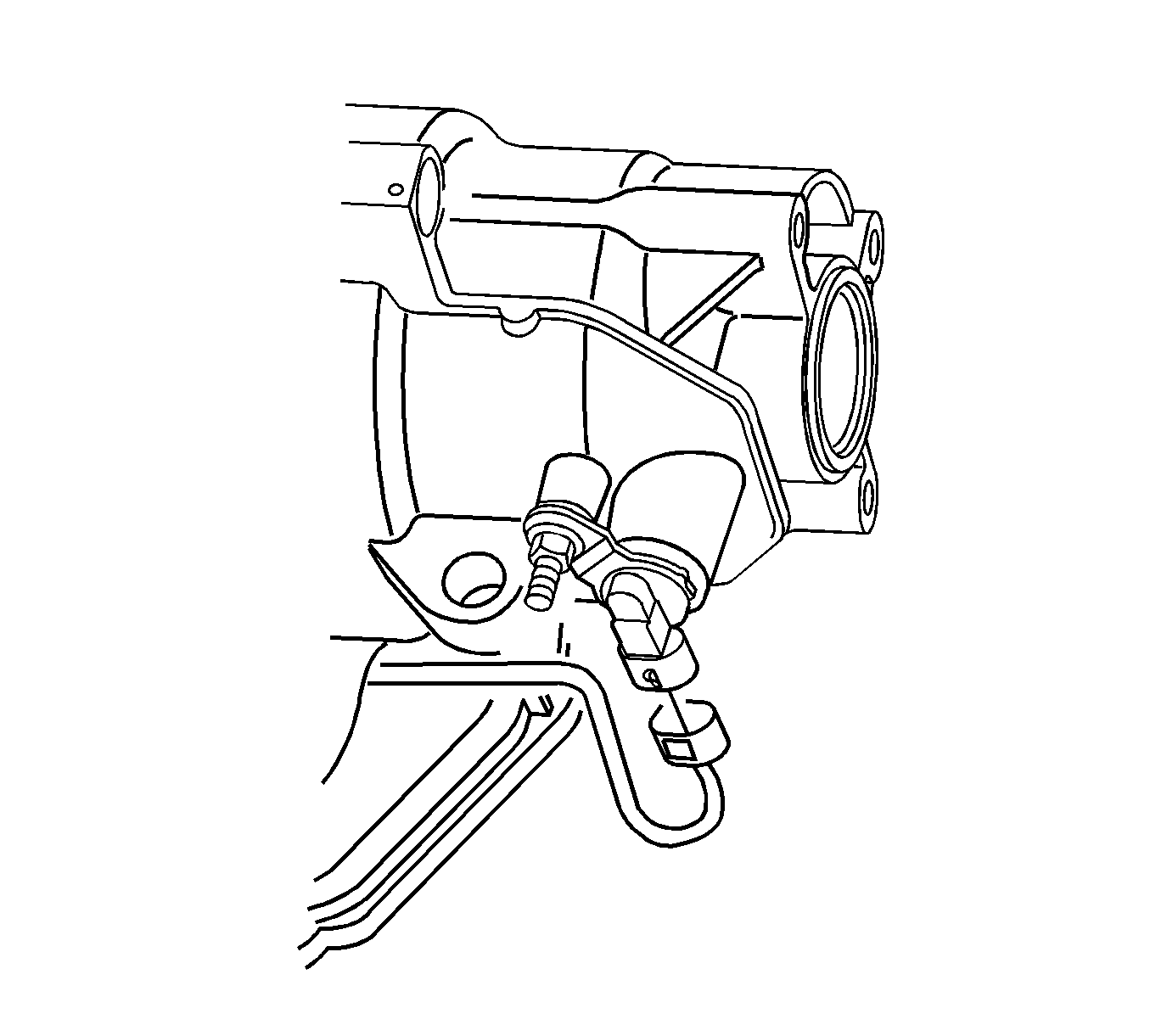

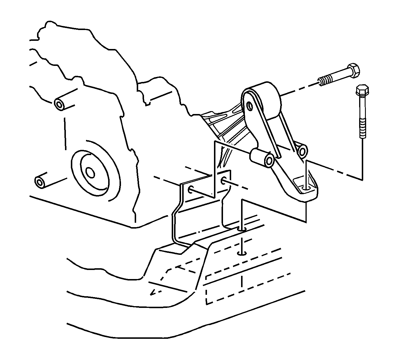
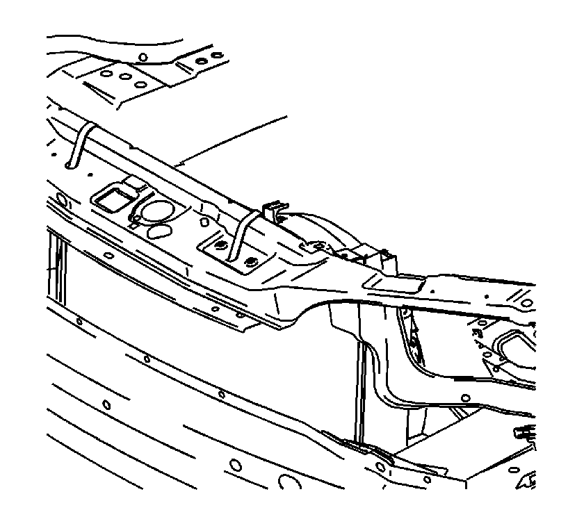
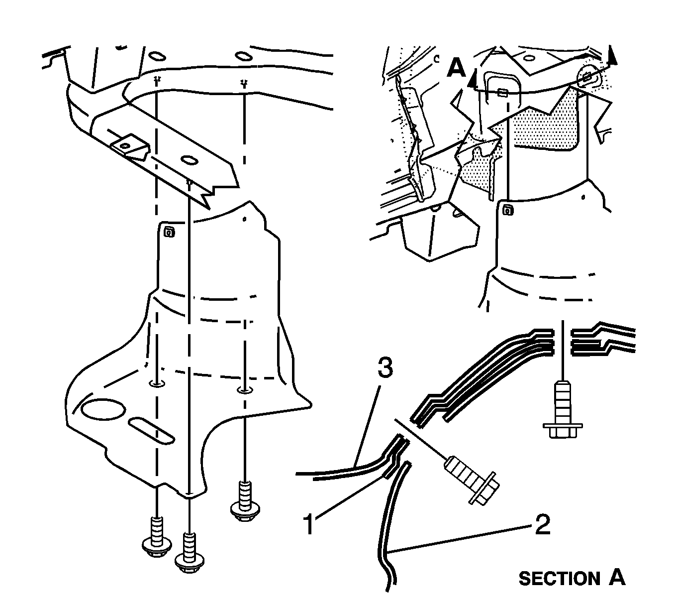
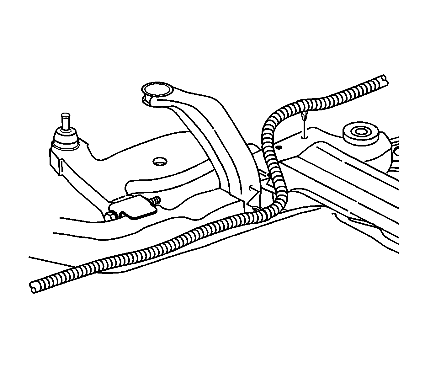
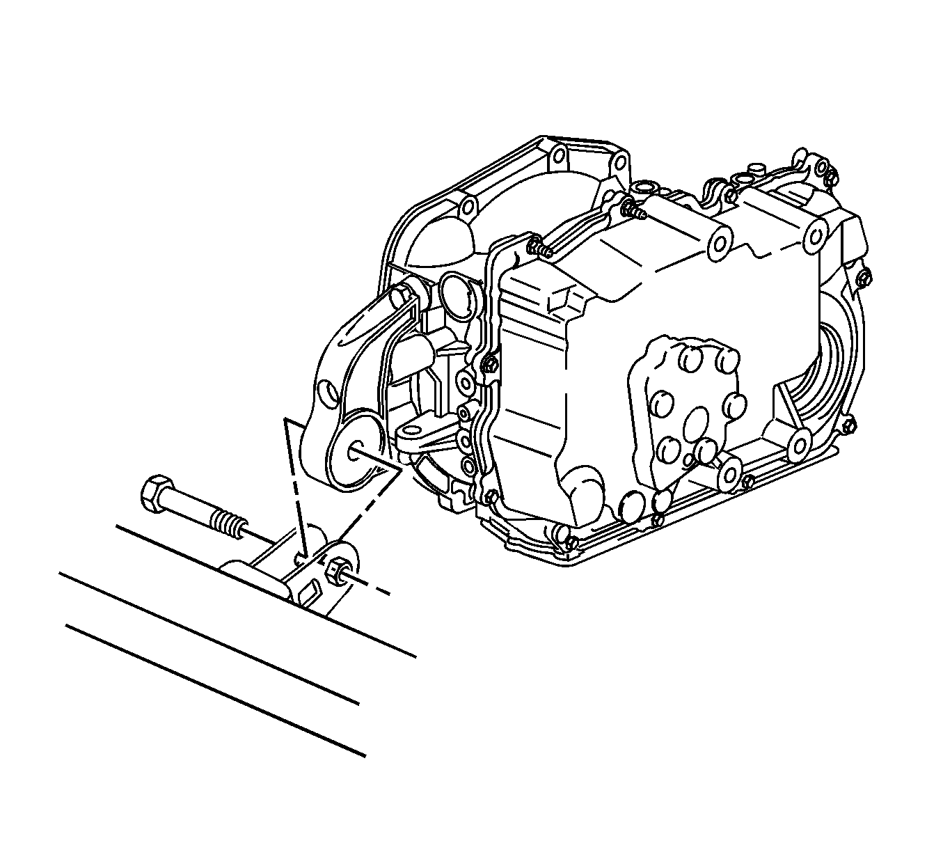
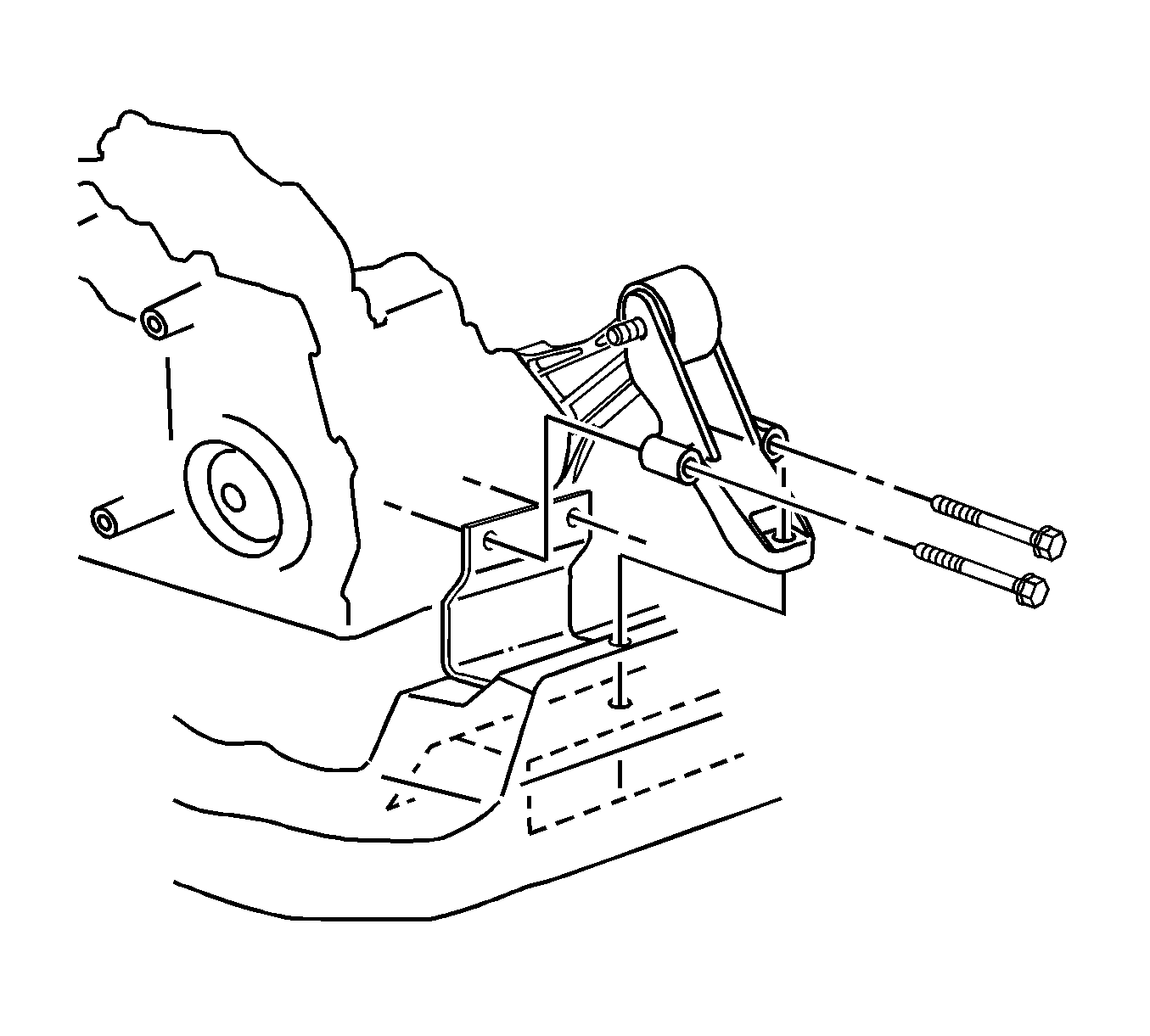
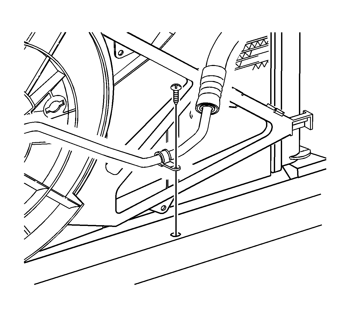
Remove the A/C line-to-frame attachment clip at front of vehicle.
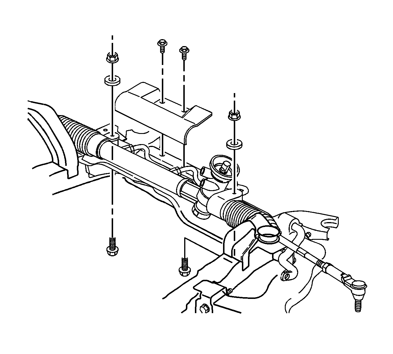
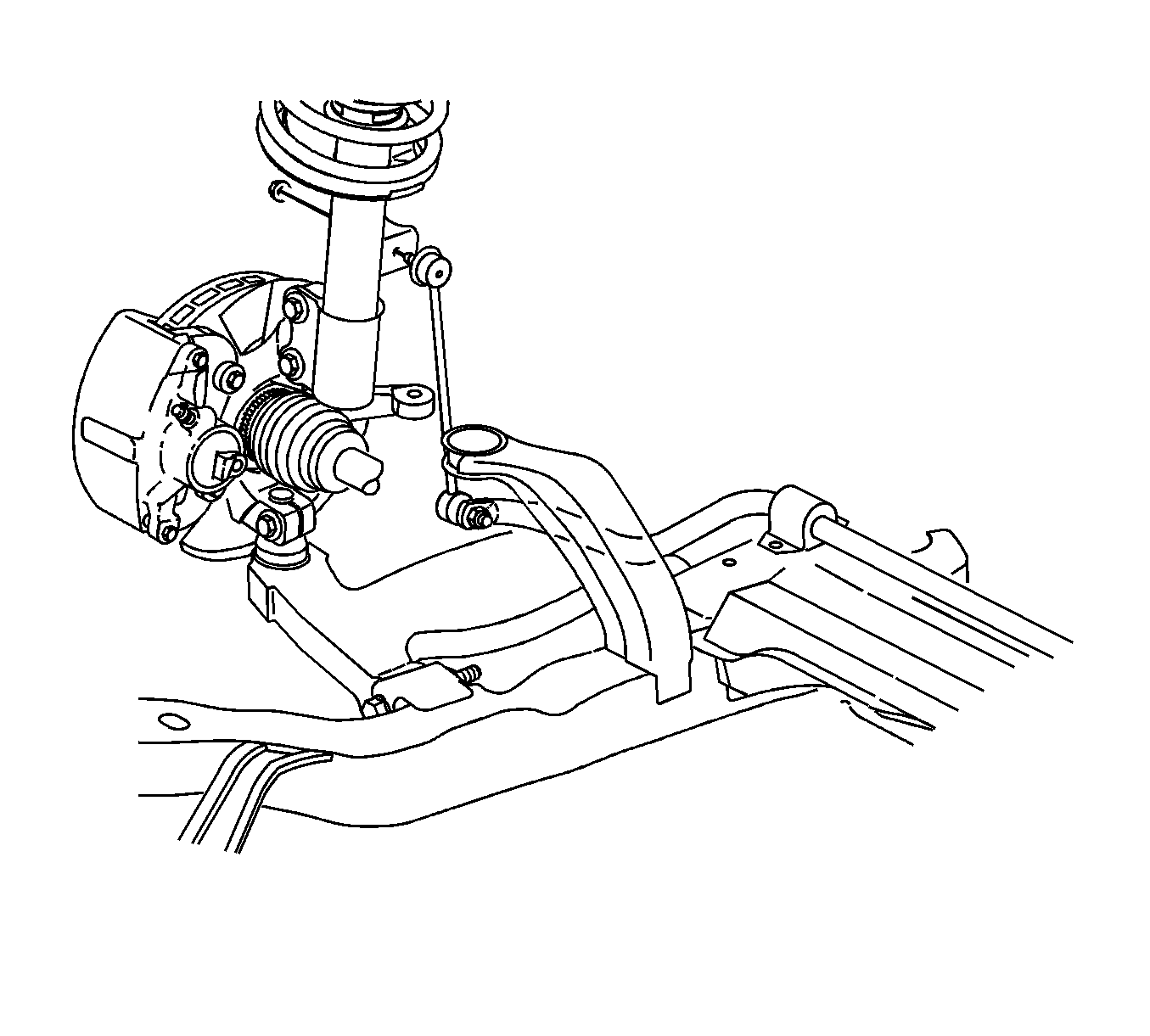
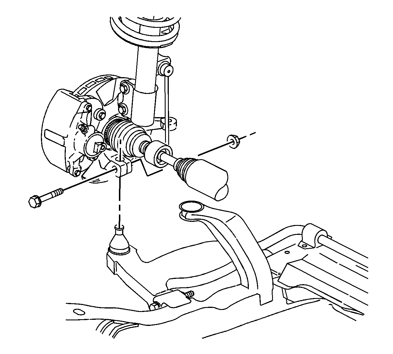
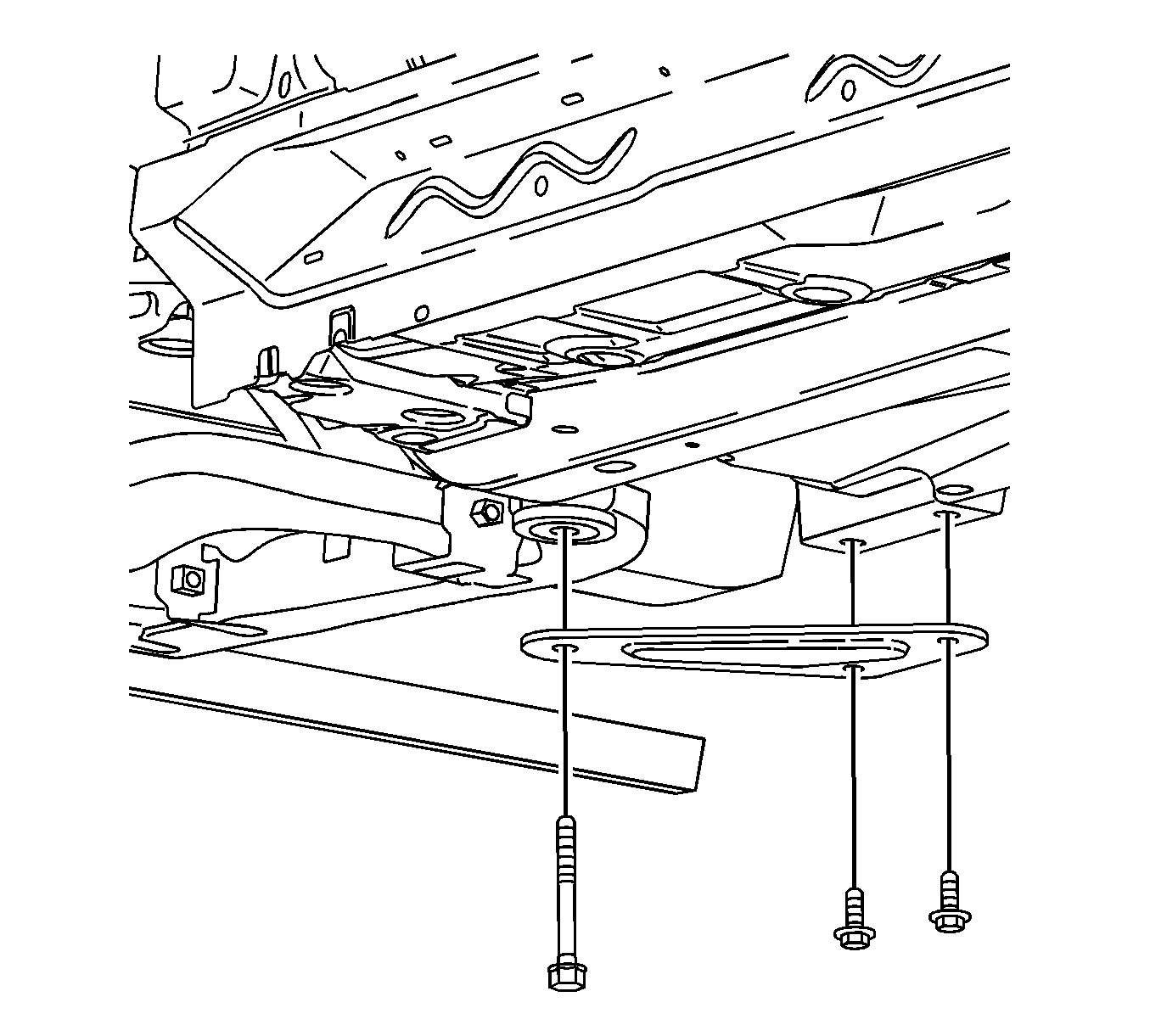
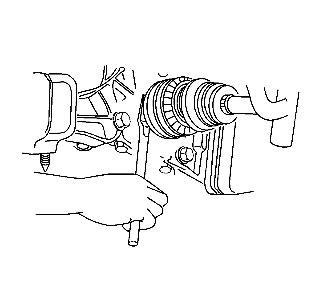
Notice: To prevent damage to CV joint boots, be careful not to allow them to contact other parts during the removal process. Also, never pull on the shaft assembly.
Notice: When removing the right hand axle shaft, the transaxle stub shaft may come out of the transaxle with the axle shaft. When this occurs, inspect the axle shaft seal in the transaxle for damage and replace if necessary.
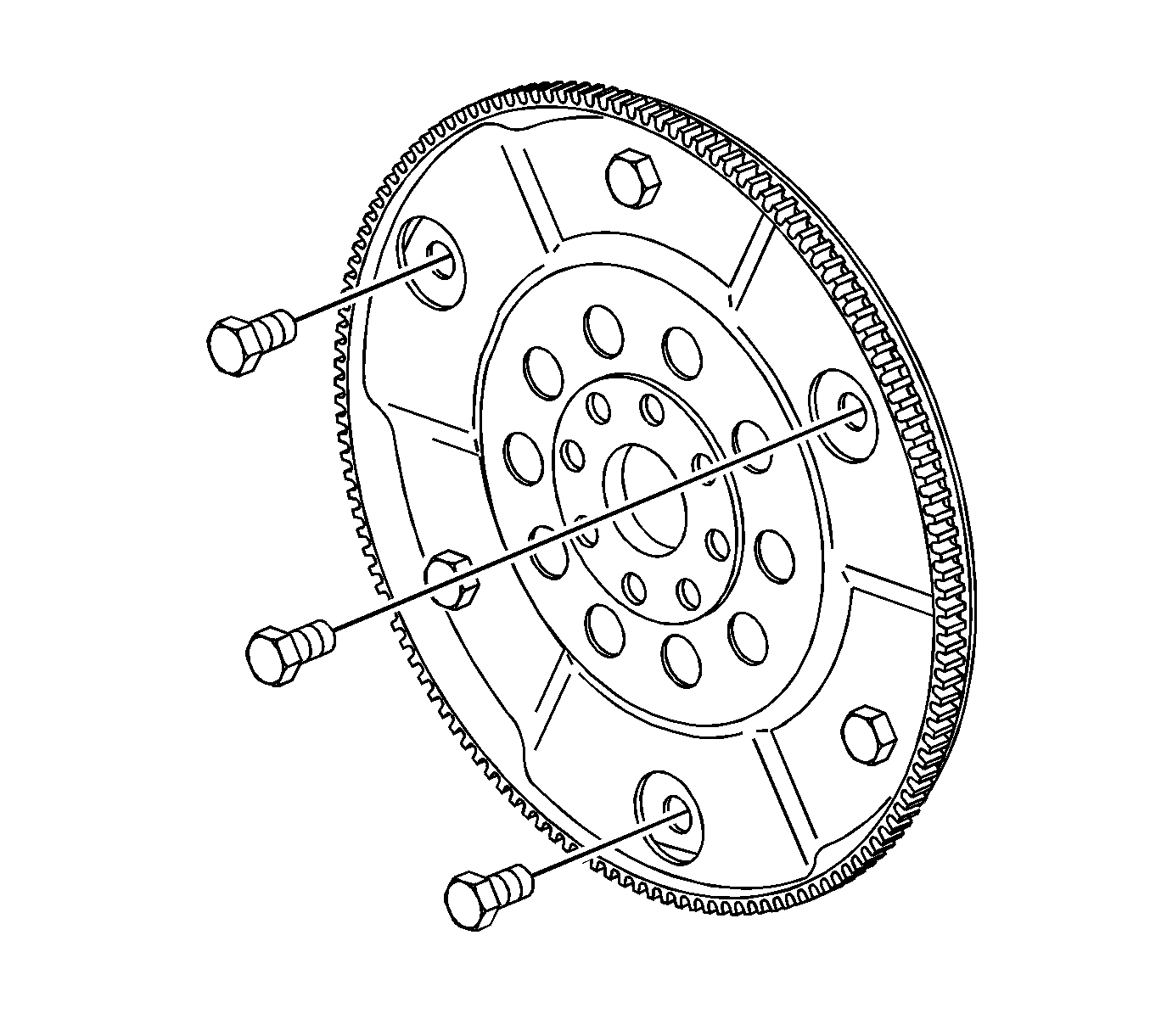
Important: The 4 cylinder flexplate has only 3 bolts and all are used to connect the flexplate to the torque converter.
Transaxle Installation Procedure
Notice: Cooler lines must be flushed prior to transaxle installation
Oil Line Cooler Flusher SA9165T should be used when flushing of transaxle oil cooler in radiator assembly is required. Follow instructions provided with the tool when performing flushing procedure.
Cooler Flusher Adapter J35944-440 is used in combination with flushing tool and allows you to attach cooler flusher to transaxle oil cooler line assembly and flush cooler and cooler lines at the same time.
The transaxle oil cooler and lines should be flushed in any of the following situations:
| • | Performing a transaxle replacement. |
| • | Oil cooler lines should be flushed after oil cooler replacement. |
| • | Any internal transaxle failure that caused debris (clutch plate material, metal shavings, etc.) to enter the transaxle oil cooler and oil cooler lines. |
- Install the new turbine shaft O-ring P/N 08677453 on end of turbine shaft.
- Install the new torque converter P/N 24211330 onto transaxle.
- Transfer range switch to new transaxle.
- Place the transaxle on the hydraulic lift table and position the table under the vehicle. Slowly lower the vehicle and position the transaxle to the engine.
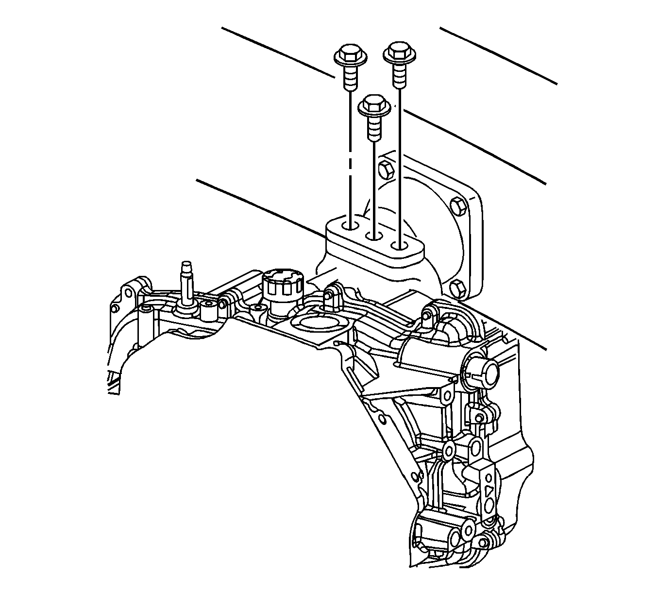
- Install the engine-to-transaxle mounting bolts as shown.
- Raise the vehicle and remove the hydraulic lift table.
- Lower the vehicle.
- Reference the alignment marks made during disassembly and install the left transaxle mount bolts.
- Raise the vehicle.
- Install the two bottom engine-to-transaxle mounting bolts.
- Install the transaxle oil cooler line assembly to the transaxle.
- Loosely install the flex plate to torque converter bolts using torque converter bolt magnetic socket J44014 through starter opening. After all the bolts are installed, torque to specification
- Install the starter assembly.
- Connect the starter solenoid electrical connections.
- Install the engine-to-transaxle bracket.
- Install new axle shaft retaining rings on end of output shafts of transaxle and install axle shafts into transaxle.
- Raise frame assembly to body.
- Install the new frame-to-body bolts P/N 11097811.
- Install the new cage nuts P/N 90468617 into body for suspension supports, as torque retention of old nuts may not be sufficient.
- Install the suspension supports using new bolts P/N 11095961. Tighten all frame bolts.
- Install the ball stud into the steering knuckle.
- Install the steering gear-to-frame using the new bolts P/N 11099501 and nuts P/N 11094487.
- Install steering gear heat shield.
- Install the stabilizer bar link-to-strut assembly.
- Install the rear transaxle mount to the frame bolts.
- Install the front transaxle mount through the bolt.
- Reattach the A/C line clip to front of frame assembly.
- Install the right front lower splash shield.
- Install the left front wheel liner push pin to frame.
- Connect the O2 sensor electrical connector and reattach harness to frame.
- Lower the vehicle and remove the engine support fixture.
- Connect the output speed sensor electrical connector. Secure the harness to the mounting stud.
- Install the remaining engine-to-transaxle mounting bolts.
- Install the transaxle electrical connector and ground wire to the transaxle.
- Install the remaining wire harness attachments to transaxle side cover.
- Install the control cable mounting bracket to rear powertrain mount.
- Connect the control cable to the transaxle range switch lever.
- Install the battery tray and battery tray fasteners.
- Install the underhood fuse block case to the battery tray and install the bolt.
- Install the wire harnesses to the fuse block case. The wire harness grommets have retaining tabs that lock into the case when the harnesses are fully installed.
- Snap the fuse block onto the fuse block case hinges.
- Install the following connectors to the underhood fuse block:
- Secure the underhood fuse block to fuse block case by rotating down and snapping into place.
- Install the underhood fuse block cover.
- Secure the coolant hose into the place on the fuse block cover.
- Install the battery feed cable to the underhood fuse block.
- Install the battery.
- Install the wheel and tire assemblies onto the hub.
- Install the wheel bolts and tighten in a crisscross pattern.
- Start the engine and operate the vehicle until the transaxle fluid temperature reaches at least 40° C (104° F).
- Depress the brake pedal and move the shift lever through all gear ranges, pausing a few seconds in each range. Return the shift lever to the PARK range.
- Raise the vehicle. Vehicle must be level, with engine running.
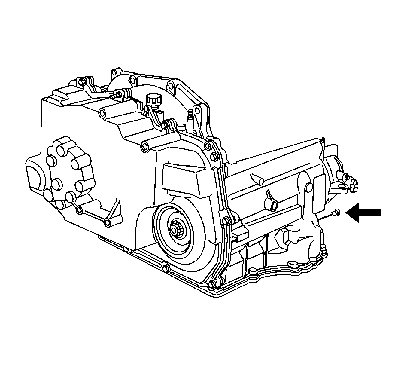
- Remove the transaxle level plug with the engine running.
- Check the fluid level. The fluid level should be even with the bottom of threaded plug hole.
- If the fluid level is low, add DEXRON® III automatic transaxle fluid in increments of 0.5 qts until fluid drains from plug hole.
- Allow the fluid to finish draining from plug hole. Install the plug, and wipe any excess fluid from transaxle with a rag or shop towel.
- Install the hose clip to the two power steering lines.
- Pull the A.I.R. tube back to the original position.
- Insert the tube into the hose and install the clamp.
- Ensure the stand-off clip between the A.I.R. tube and the wiring harness is installed correctly.
- Install the remaining rear transaxle mount-to-frame bolts.
- Install the rear powertrain mount through bolt.
- After the frame assembly has been installed it will be necessary to adjust the front wheel toe.
- Position and lock steering in the straight-ahead position.
- Loosen the left side and the right side inner tie rod-to-outer tie rod jam nuts.
- Use a wrench on the inner tie rod flats to turn the inner tie rods in the direction of desired change.
- After the toe adjustment is complete, tighten the left side and right side inner tie rod-to-outer tie rod jam nuts.
- Re-check the toe angles to ensure proper adjustment and re-adjust if necessary.
- Road test the vehicle to verify proper operation.
- Affix Campaign Completion Label on a clean and dry surface of radiator core support, in an area clearly visible when hood is raised. (For more information, refer to "Campaign Completion Label" in this bulletin.)


Notice: Transaxle cooler lines must be flushed before transaxle installation
Important: The bottom two and top three engine-to-transaxle mounting bolts will be installed later in this procedure.
Tighten
Tighten the engine-to-transaxle bolts to 65 N·m(48 lb ft).

Notice: If the powertrain mount is not reinstalled in its original position, it could lead to premature mount wear.
Tighten
The transaxle mount (left)-to-transaxle mount bracket
bolts to 55 N·m(41 lb ft).
Tighten
Tighten the engine-to-transaxle bolts to 65 N·m(48 lb ft).

Notice: Failure to lubricate the inside of the cooler line seals with DEXRON® III P/N 21019223 automatic transaxle fluid before installing the cooler line assembly into the seals may cause damage to the seals.
Tighten
Tighten the transaxle oil cooler line assembly nut
to 8 N·m(71 lb in).
Notice: Torque Converter Bolt Magnetic Socket must be used to install the flex plate to torque converter bolts. Care must be taken not to drop the bolts inside the torque converter housing of the transaxle. If a bolt is dropped inside the housing, the transaxle must be separated from the engine to retrieve it.
Tighten
Tighten the flex plate-to-torque converter bolts
to 45 N·m (33 lb ft).

Tighten
Tighten the starter assembly bolts to 40 N·m(30 lb ft).

Tighten
Tighten the engine harness (1)-to-starter
solenoid nut to 4.5 N·m (40 lb in).
Tighten
Tighten the battery terminal (2)-to-starter
solenoid nut to 9 N·m (80 lb in).

Tighten
tighten the engine-to-transaxle bracket bolts to
35 N·m (26 lb ft).
Notice: In order to prevent damage to axle shaft splines during vehicle operation, add grease P/N 07847638 (or equivalent) to splines prior to installing axle shafts.
Notice: Install new cage nuts into the body as torque retention of old nuts may not be sufficient.
Important: Be sure the frame alignment tool fully engages in all gage holes.

Important: Do not tighten fasteners at this time.

Tighten
Tighten the suspension support-to-frame bolts to
90 N·m (66 lb ft) + 45° to 60°

Tighten
Tighten the lower control arm-to-steering knuckle
nut and bolt to 100 N·m (75 lb ft).

Tighten
Tighten the steering gear-to-frame assembly bolts
to 45 N·m (33 lb ft) + 45° to 60°.
Tighten
Tighten the steering gear heat shield to 4 N·m(35 lb in).

Tighten
Tighten the stabilizer bar link-to-strut assembly
65 N·m (48 lb ft).

Tighten
Tighten the transaxle mount (rear)-to-frame assembly
bolts to 60 N·m (44 lb ft).

Tighten
Tighten the front transaxle through bolt to 55 N·m
(41 lb ft).


Tighten
Tighten the splash shield fasteners 5 N·m
(44 ft lb).


Tighten
Tighten the engine-to-transaxle bolts to 65 N·m
(48 lb ft).

Tighten
Tighten the ground wire bolt to 25 N·m
(18 lb ft).
Tighten
Tighten the wiring harness attachment fasteners
to 20 N·m (15 lb ft).

Tighten
Tighten the control cable mounting bracket bolts
to 20 N·m (15 lb ft).

Tighten
Tighten the battery tray bolts to 15 N·m
(11 lb ft).

Tighten
Tighten the underhood fuse block case bolt to 9 N·m
(80 lb in).
| • | Engine (1) |
| • | Forward lamp (2) |
| • | Instrument Panel (I/P) (3) |

| • | Engine 68 way (1) |
| • | Forward Lamp 68 way (2) |
| • | I/P 68 way (3) |
| • | Forward Lamp 2 way (White) (4) |
| • | I/P 2 way (Black) (5) |
| • | I/P 2 way (Green) (6) |
| • | I/P 2 way (Brown) (7) |

Tighten
Tighten the battery feed cable-to-underhood fuse
block bolt 16 N·m (12 lb ft).

| 47.1. | Install the battery into battery tray. |
| 47.2. | Install the battery hold-down bracket. |
Tighten
Tighten the battery hold down bracket bolt to 20 N·m
(15 lb ft).
| 47.3. | Install the fan control module by sliding down onto the battery hold-down bracket. |
| Caution: THE POSITIVE BATTERY TERMINAL MUST BE CONNECTED FIRST TO PREVENT ARCING. |
| 47.4. | Install battery cables (positive first, negative second). |
Tighten
Tighten the battery cable-to-battery to 17 N·m
(13 lb ft).
Caution: BEFORE INSTALLING WHEELS, REMOVE RUST OR CORROSION FROM WHEEL MOUNTING SURFACES AND BRAKE ROTORS. FAILURE TO DO SO CAN CAUSE WHEEL BOLTS TO LOOSEN IN SERVICE.
| 49.1. | Hand tighten all five wheel bolts. |
| 49.2. | Use a torque wrench to tighten the wheel bolts using a crisscross pattern. |
Tighten
Tighten the wheel bolts (initial torque) to 63 N·m
(46 lb ft).
| 49.3. | Use a torque wrench to final tighten wheel bolts using a crisscross pattern. |
Tighten
Tighten the wheel bolts (final torque) to 125 N·m
(92 lb ft).
Important: If a new transaxle assembly was installed, the transaxle was filled with the proper amount of transaxle fluid at the factory. No additional fluid is required.
Caution: MAKE SURE VEHICLE IS PROPERLY SUPPORTED AND SQUARELY POSITIONED ON THE HOIST. TO HELP AVOID PERSONAL INJURY WHEN A VEHICLE IS ON A HOIST, PROVIDE ADDITIONAL SUPPORT FOR THE VEHICLE ON THE OPPOSITE END FROM WHICH COMPONENTS ARE BEING REMOVED.
Caution: THE TRANSAXLE FLUID IS HOT. CAUTION MUST BE TAKEN TO PREVENT PERSONAL INJURY IN THE EVENT TRANSAXLE FLUID DOES DRAIN FROM THE PLUG HOLE AFTER THE PLUG IS REMOVED.
Notice: Saturn ATF (P/N 21005966) is not compatible with this transaxle. If Saturn ATF is used, transaxle damage will result. This transaxle uses DEXRON® III ATF (P/N 21019223).
Important: Before re-installing the transaxle level plug, apply Loctite Threadlocker 242®.
Tighten
Tighten the transaxle fluid level plug to 12 N·m
(9 lb ft).

Important: The clamp must be installed with the locking portion facing down. 59. Insert the tube into the hose and install the clamp.
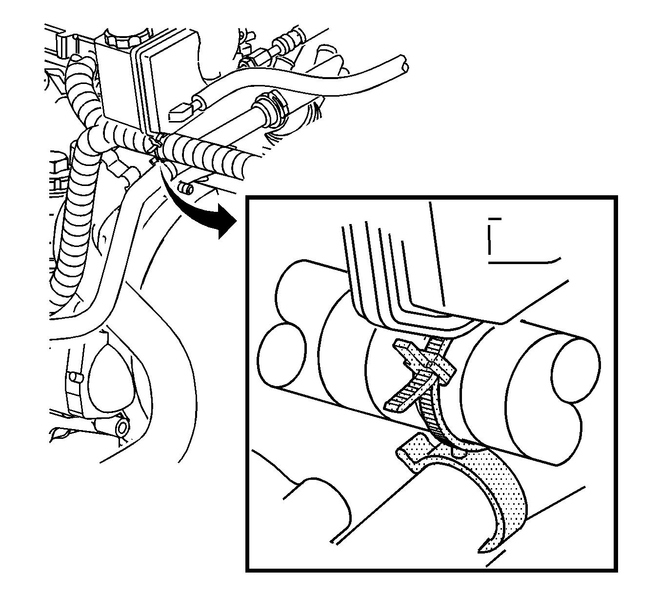
Notice: There is a stand-off clip between the A.I.R. tube and the wiring harness at the front of the transaxle. This must be in place to eliminate the possibility of chaffing between the tube and the harness.

Tighten
Tighten the transaxle mount (rear)-to-frame assembly
bolts to 60 N·m (44 lb ft).
Tighten
Tighten the mount (rear) through bolts to 90 N·m
(66 lb ft).
Important: When performing front wheel toe adjustment, ensure that steering wheel is locked in the straight-ahead position.
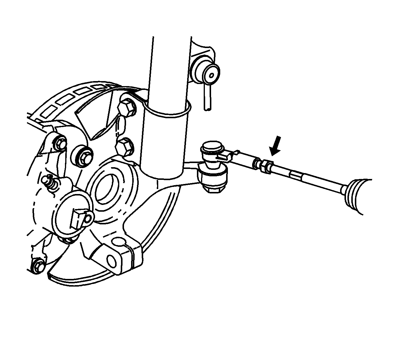
Notice: Make sure seals on steering gear assembly do not rotate and become twisted. If these seals rotate and become twisted, seal damage may result.
Tighten
Tighten the inner tie rod-to-outer tie rod jam nuts
to 60 N·m (44 lb ft).
Important: Do not cover any existing underhood labels when affixing Campaign Completion Label.
Campaign Completion Label
Upon completion of the campaign, aCampaign Completion Label and a Clear Protective Cover should be affixed on a clean, dry surface of the radiator core support in an area clearly visible when the hood is raised. Each label provides a space to print in ink (or type) the campaign number (01C07) and the five (5) digit facility code of the Retailer performing the campaign service.
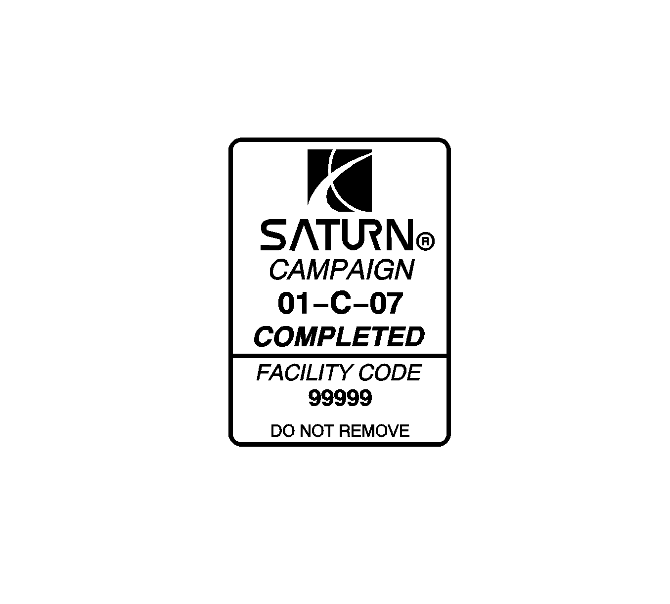
As a reminder, additional labels may be ordered from Saturn publications (1-800-828-2112, prompt 3, Item # S03 00013A for the Campaign Completion Label , and Item#S03 00013B for the Clear Protective Cover) .
Credit
1. To receive credit, submit a claim with the information below:
Repair Performed | Parts Allow. | Sale Type | Case Type | Labor Op. | Labor Hrs. | Admin. Hrs.** |
|---|---|---|---|---|---|---|
Inspect transaxle torque converter paint ID mark Add Remove the transaxle and inspect julian date and time stamp on torque converter and reinstall | * | WC | VC | V0705 | 0.2 6.1 | 0.1 |
Inspect the transaxle torque converter ID marks and replace torque converter | * | WC | VC | V0706 | 6.4 | 0.1 |
Inspect transaxle torque converter ID marks and replace transaxle | * | WC | VC | V0707 | 6.5 | 0.1 |
2. To receive credit for loaner/rental car costs incurred while owner awaits campaign repair or other goodwill expenses, submit a claim with the information below:
Repair Performed | Sale Type | Case Type | Labor Op. | Net Item Amount | Net Item Code | # Days Rental |
|---|---|---|---|---|---|---|
Loaner Reimbursement - 4T40E transaxle/torque converter | WC | VC | Z4152 | *** | C | **** |
Other Goodwill - 4T40E transaxle/torque converter | WC | VC | Z4153 | *** | R | N/A |
3. Retailers are empowered to use good judgement regarding loaner/rental cars or any other goodwill expenses deemed necessary. It will not be necessary to call the Saturn Customer Assistance Center for authorization of goodwill. The Goodwill Worksheet (printed towards the back of this bulletin) must be used to document goodwill expenses. The completed Goodwill Worksheet must be attached to the hard copy of the CSO. Retailers are to make sufficient copies of the blank Goodwill Worksheet to document goodwill expenses.
4. Check your Saturn SERVICELINE.XL Claim Memorandum daily. Remember to code the claim as a WC sale type, and VC case type. Contact your field representative if you need assistance.
5. All labor operations claimed in this bulletin must be submitted on individual (unrelated) CSO lines. Refer to the Customer Service Order Preparation Manual for details on Product Campaign Claim Submission.
* The parts allowance should be the sum total of the current SSPO Retailer net price plus 30% of all parts required for the repair.
** Campaign administrative allowance.
*** Net amount must be submitted as a miscellaneous sale...Loaner reimbursement not to exceed $30/day.
**** Enter number of days vehicle was rented...Not to exceed 1 day.
01-C-07 GOODWILL WORKSHEET
As stated in the "Credit" section of this bulletin, Retailers are empowered to use good judgement regarding loaner/rental cars or other goodwill expenses that might become necessary for customer satisfaction.
Complete this worksheet and attach it to the hard copy of the Customer Service Order (CSO) to document all campaign goodwill claims submitted to Saturn.
VIN #
A. Vehicle Loaner/Rental Allowance Explanation: | $ | ||||
| |||||
| |||||
| |||||
Repair Performed | Sale Type | Case Type | Labor OP | Net Item Code | # Days Rental |
Loaner Reimbursement-4T40E Transaxle/torque converter | WC | VC | Z4152 | C | * |
* Not to exceed $30/day for 1 day | |||||
B. Other/Goodwill Allowance Explanation (Specify what was done and why): | $ | ||||
| |||||
| |||||
| |||||
Repair Performed | Sale Type | Case Type | Labor OP | Net Item Code | # Days Rental |
Other Goodwill - 4T40E Transaxle/torque converter | WC | VC | Z4153 | R | N/A |
| |||||
| |||||
| |||||
Authorized Retailer Signature | |||||
(Please copy this form as necessary) | |||||
Dear Saturn Owner:
Saturn has decided that certain 2001 L-Series Saturn vehicles may exhibit a condition in which the transaxle converter pump to stator bearing may prematurely fail due to a raised metal condition on the bearing surface on the inside of the pump cover. This may cause abnormal transaxle noise and may lead to premature failure.
To prevent the possibility of this condition occurring, Retailers will inspect the torque converter for certain production date codes, and, if necessary replace the transaxle.
What Saturn Will Do
Saturn will inspect the torque converter and, if necessary, replace the transaxle. This service will be performed for you at no charge.
What you should do
Contact your Saturn Retailer to arrange to have this service performed. The inspection procedure will take approximately one half hour. However, if the transaxle requires replacement the repair, could take an additional six hours. Additional time may be required for paperwork and processing.
Your Retailer is prepared to perform this service promptly and with minimal inconvenience to you. If you have any questions or need assistance, please contact your Retailer or the Saturn Customer Assistance Center at 1-800-553-6000 prompt 3, or for the hearing impaired, 1-800-833-6000.
Again, we sincerely regret any inconvenience or concern this situation may cause you. We want you to know that we will do our best, throughout your ownership experience, to ensure that your Saturn provides you many miles of enjoyable driving.
Sincerely,
Saturn Corporation
01-C-07
