DTC P0562 L81
Circuit Description

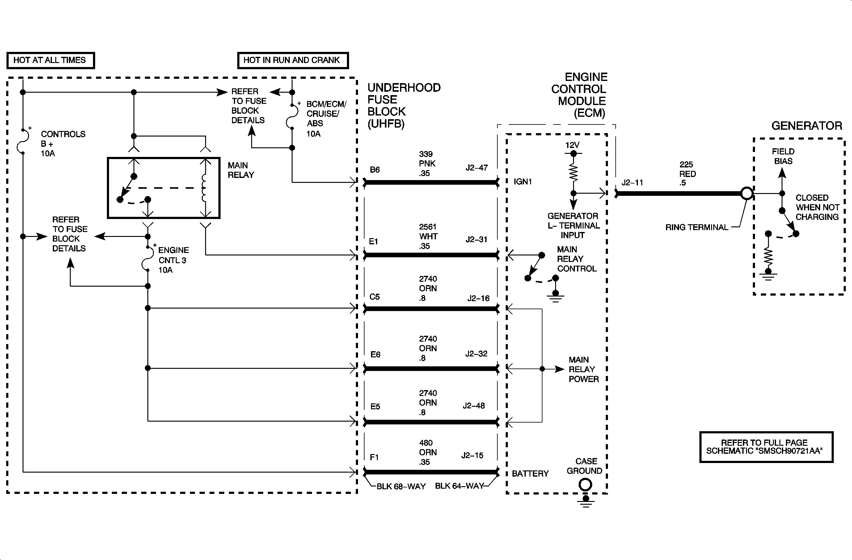
The engine control module (ECM) monitors vehicle system voltage by monitoring the voltage on circuit 2740 coming from the main relay, which is referenced to the ECM case ground. Each of the 3 main relay pins going into the ECM are tied together internally in the ECM. When ignition voltage is present at the ignition 1 input to the ECM, circuit 339, the ECM will command the main relay ON by supplying ground to the main relay coil circuit. When the relay is energized, battery voltage should be present on each circuit 2740 at the ECM. DTC P0562 will set if the ECM detects lower than normal system voltage on circuit 2740 for a certain length of time after the engine has been running when the main relay has been commanded ON.
Conditions for Setting the DTC
DTC P0562 will set if system voltage measured at the ECM main relay voltage circuit 2740 is less than 9 volts when:
| • | The condition exists for longer than 0.2 seconds. |
| • | The main relay is commanded ON because the ECM detected ignition voltage present at the ignition 1 input to the ECM. |
| • | The engine run time is greater than 3 minutes. |
| • | Vehicle speed is present. |
DTC P0562 diagnostic runs continuously once the above conditions have been met.
DTC P0562 is a type D DTC.
Diagnostic Aids
Important: If a generator L-terminal DTC is also set, diagnose that DTC first. A fault in the charging system may set this DTC.
DTC P0562 indicates that the battery voltage supplied through the main relay to circuit 2740 was low, which most likely indicates a charging system problem.
To locate an intermittent problem, use the scan tool to monitor BATTERY voltage with the engine running at 1,300 RPM. With all accessories ON or all accessories OFF, charging voltage should be in the range of 12.5-15.5 volts.
Compare BATTERY voltage on the scan tool with the actual voltage measured at the battery with a DVOM. If readings do not fall within +/- 0.2 volts, check the battery cables and the ECM case ground bolts for tightness and for battery terminal corrosion.
Perform a charging system test. Refer to Starting and Charging Section in this service manual.
DTC P0562 L61

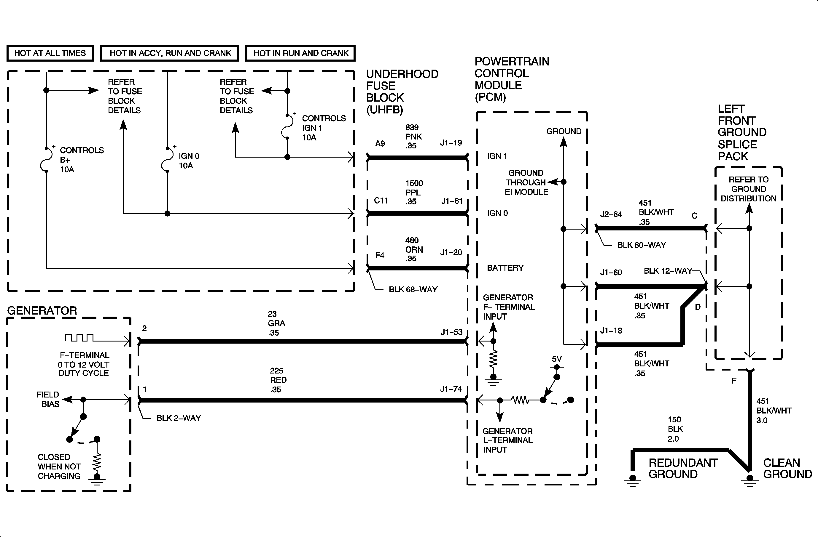
The PCM monitors ignition voltage on circuit 839 at all times with reference to circuit 451 (ground) when the engine is running. Ignition voltage from circuit 439 can be read on the scan tool as IGNITION 1 voltage. DTC P0562 sets when the PCM detects low system voltage. DTC P0563 sets when the PCM detects high system voltage. These values are out of the normal charging system voltage range.
Conditions for Setting the DTC
DTC P0562 will set if ignition voltage is less than 10 volts when:
| • | The condition exists for longer than 4 minutes. |
| • | The engine speed is greater than 1,300 RPM. |
| • | The voltage of 10 volts occurs twice in the ignition cycle. |
DTC P0563 will set if ignition voltage is greater than 17 volts when:
| • | The engine is running. |
| • | The condition exists for longer than 4 minutes. |
| • | The voltage of 17 volts occurs twice in the ignition cycle. |
DTC P0562 and P0563 diagnostics run continuously with the engine running.
DTC P0562 and P0563 are type D DTCs.
Diagnostic Aids
If DTC P0621 is set, diagnose that DTC first. A circuit fault in the generator L-terminal circuit will cause the generator not to charge and may set DTC P0562.
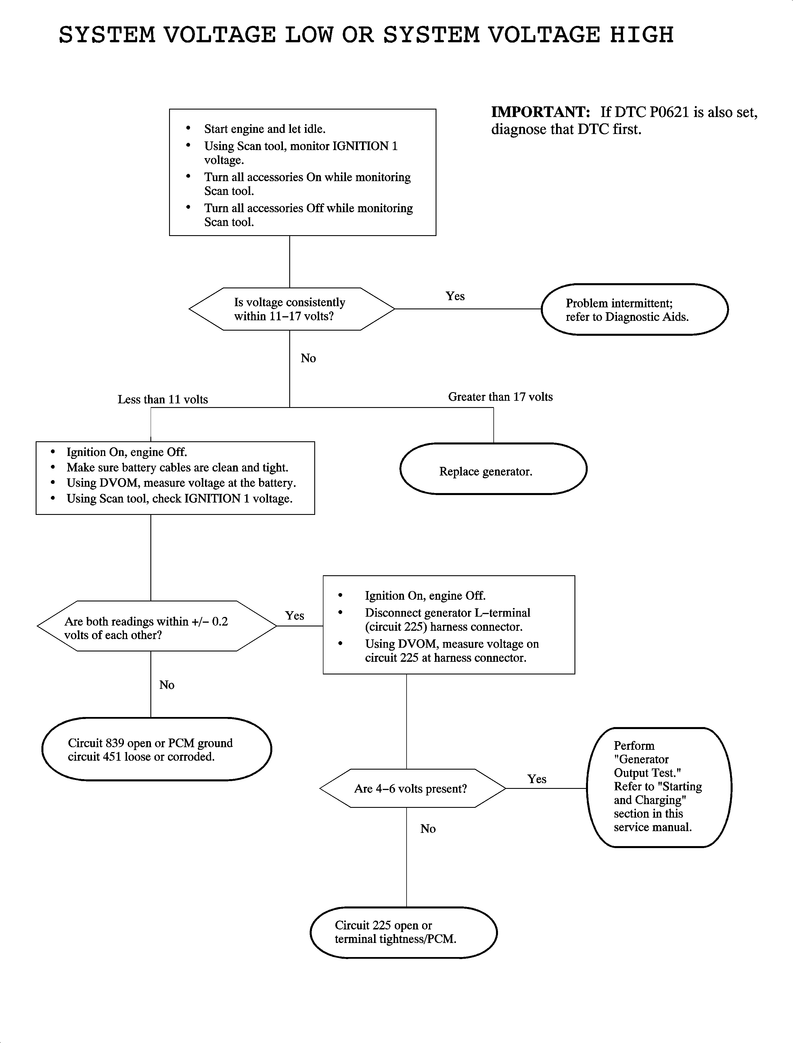
To locate an intermittent problem, use the scan tool to monitor IGNITION 1 voltage with the engine running, with all accessories ON or all accessories OFF. Changing voltage should be in the range of 12.5-15.5 volts.
With the engine OFF, compare IGNITION 1 voltage on the scan tool with actual battery voltage with a DVOM. If the readings do not fall within +/-0.2 volts, check circuit 839 and 451 for corrosion and tightness.
Perform a charging system test. Refer to "Starting and Charging Section" in this service manual.

