Circuit Description
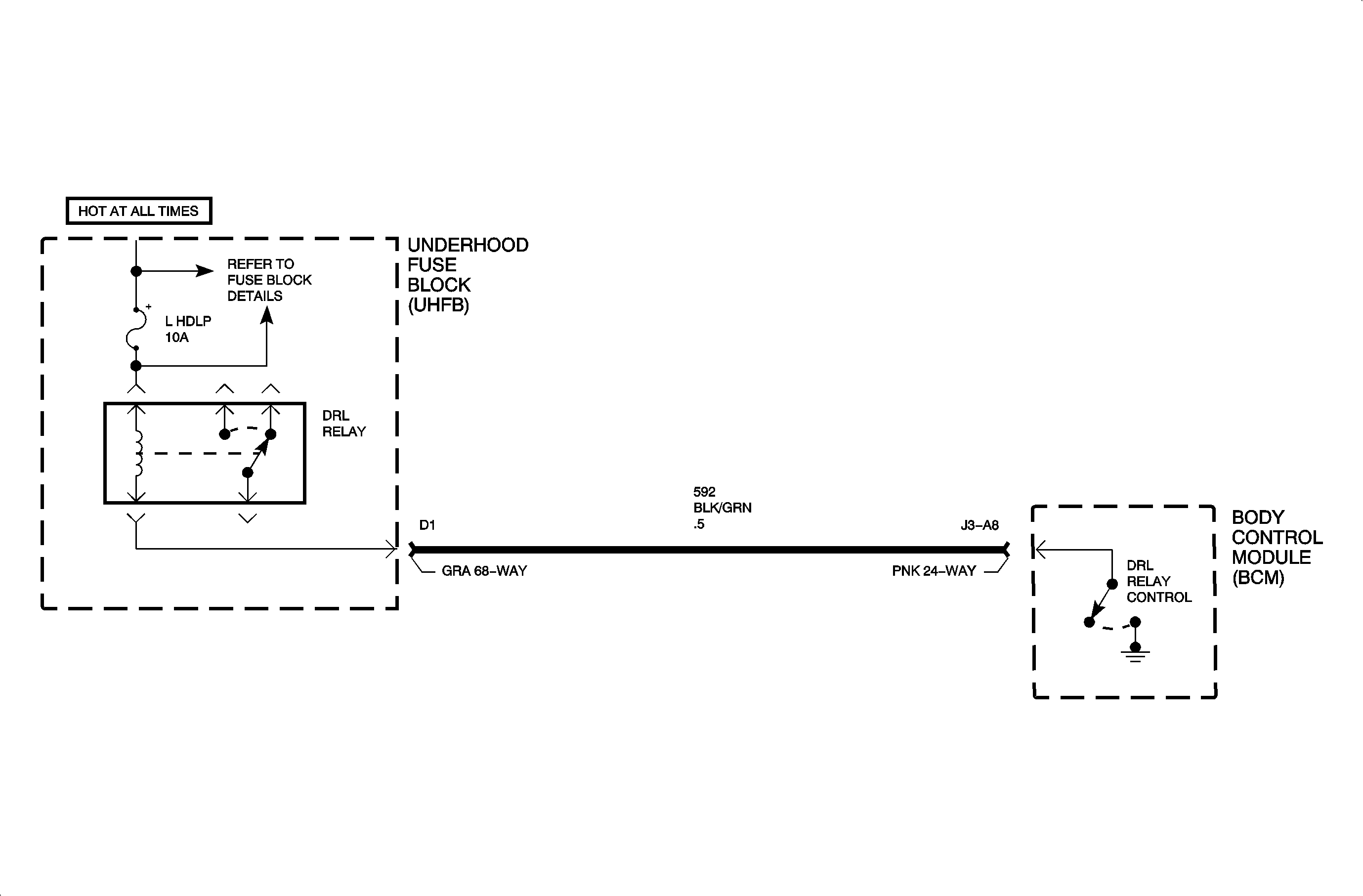
Daytime running lamps (DRL) are controlled by the body control module (BCM)
based on input from the high beam headlight circuit 1200, the low beam headlight
circuit 1201, the parking brake circuit 1134, and the ignition switch
state.
When DRL operation is desired, the BCM switches circuit 592 to ground.
This action energizes the DRL relay. When energized, the DRL relay operates the left
high beam headlight and right high beam headlight as a series circuit, with one-half
of battery voltage across each high beam headlight.
When DRL operation is not desired, the BCM does not provide ground for the DRL
relay. When not energized, as when high beam headlights are desired, the DRL relay
operates the right and left high beam headlights as a parallel circuit, with full
battery voltage across each high beam headlight.
For DRL operation, the parking brake must be fully released, the ignition switch
must be in the RUN position, and the headlight switch must be in the OFF
position. Under normal operating conditions, the feedback voltage to the BCM measured
at circuit 1200 is 6-8 volts.
DTC Parameters
| • | The ignition is in the RUN position. |
| • | The DRL is commanded ON. |
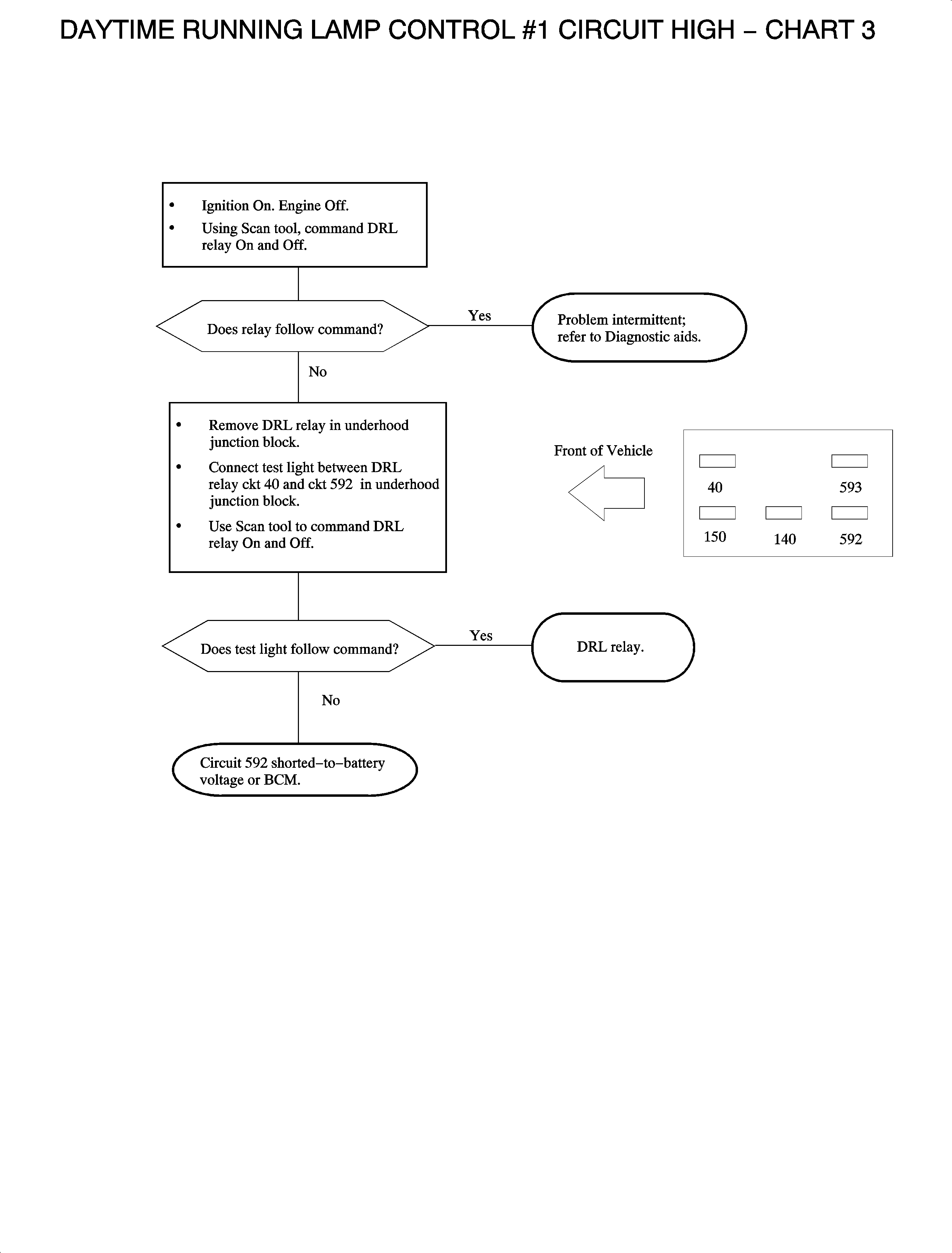
| • | Circuit 592 is shorted-to-battery voltage. |
Diagnostic Aids
| • | Check for a poor connection at the BCM. Inspect the harness connectors
for backed out terminals, improper terminal mating, broken connector locks, improperly
formed or damaged terminals, and poor terminal-to-wire connection (terminal crimped
over wire insulation and not conductors). |
| • | Inspect the wiring harness for damage. Check for broken or chaffed insulation. |
| • | If a fault is suspected to be intermittent, wiggling the harness wiring
may help in locating the fault. |


