Water Pump Replacement L61
Tools Required
J 43651 Water Pump Holding Tool
Removal Procedure
- Disconnect the negative battery cable.
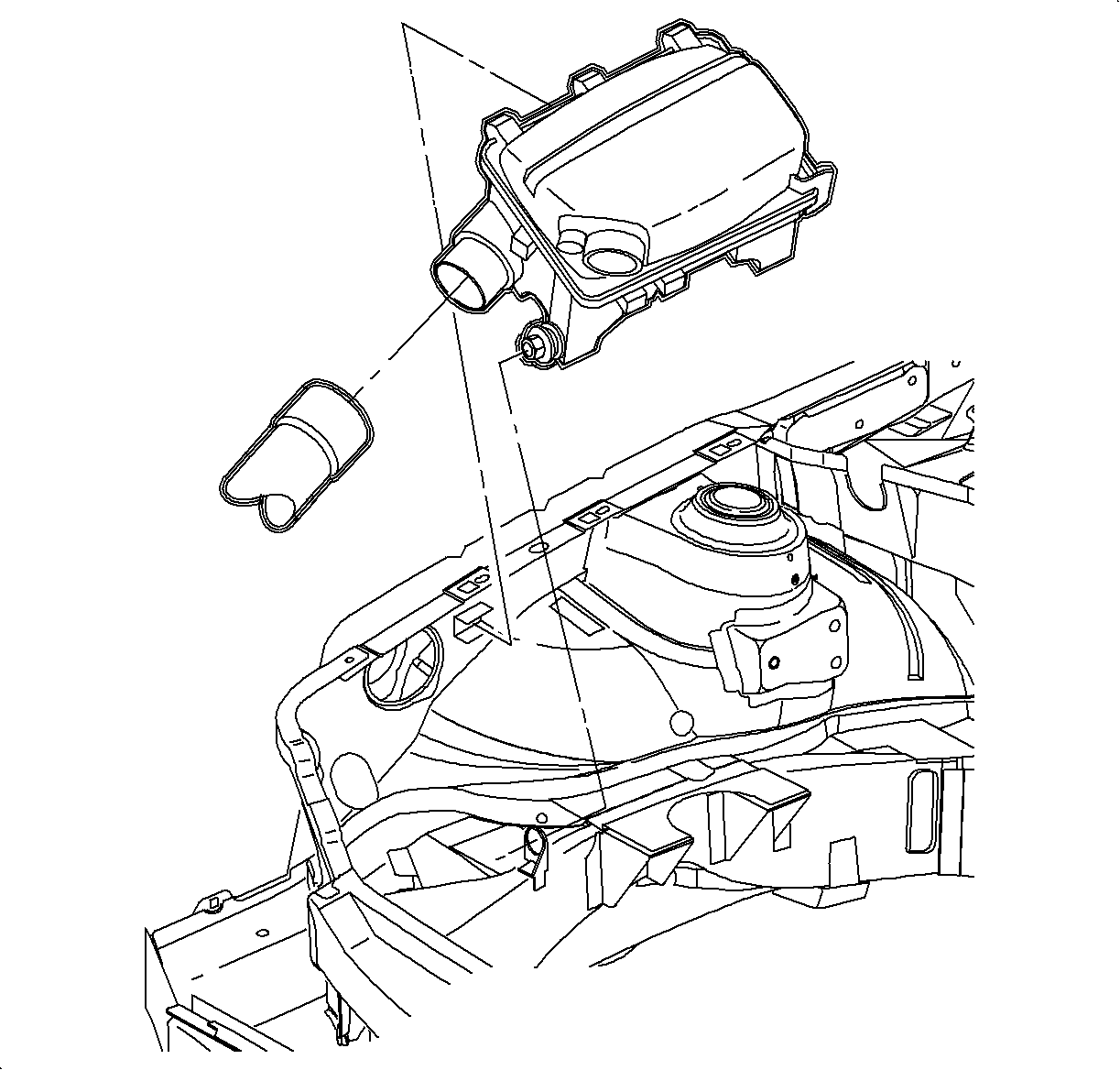
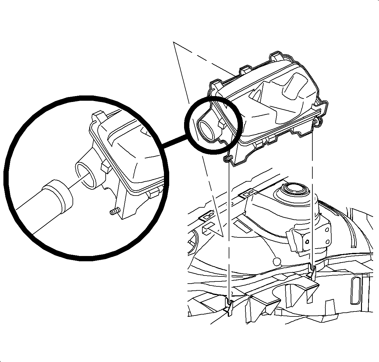
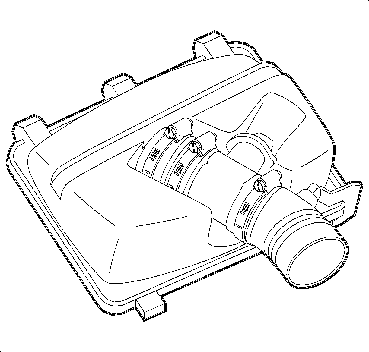
- Remove the air inlet tube and the air cleaner assembly. Refer to Air Cleaner Element Replacement .
- Drain the coolant. Refer to Engine Coolant Check and Replacement .
- Remove the exhaust manifold heat shield.
- Remove the thermostat and the water feed assembly bolts.
- Remove the water pump sprocket access plate from the front cover.
- Use the bolts removed from the sprocket access plate and install the J 43651 .
- Remove the water pump sprocket bolts.
- Remove the water pump retaining bolts.
- Remove the water pump assembly.
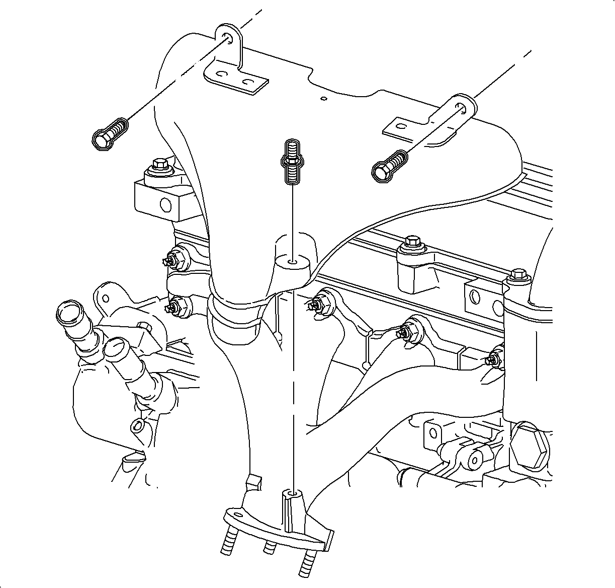
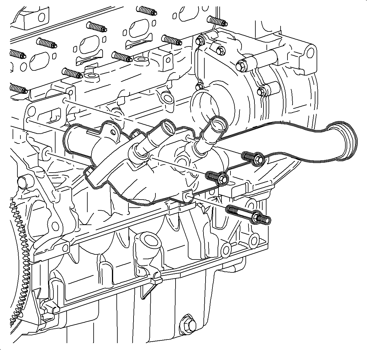
Important: Twist the water feed pipe while pulling to remove it from the water pump.
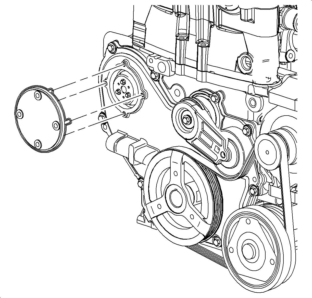
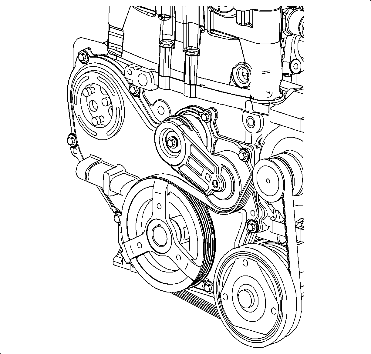
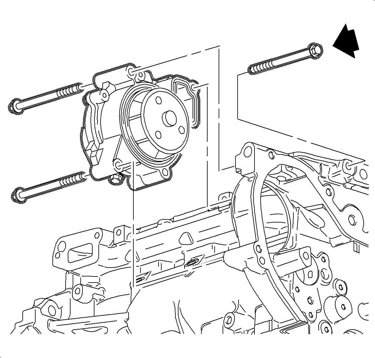
Important: Be sure to remove the retaining bolt that is accessed from the front of the engine block.
Installation Procedure
- Install the water pump assembly.
- Install the water pump bolts. Initially finger tighten the bolts.
- Install the water pump sprocket and retaining bolts.
- Remove the J 43651 .
- Install the water pump sprocket access plate.
- Install the water feed tube.
- Lubricate the feed tube O-ring with silicone gel lubricant.
- Install the water feed tube by twisting and pushing it toward the water pump. Take care not to tear or damage the O-ring.
- Install the thermostat housing to block bolts.
- Install the exhaust manifold heat shield.
- Install the air cleaner assembly and the air inlet tube. Refer to Air Cleaner Element Replacement .
- Connect the negative battery cable.
- Add the coolant.
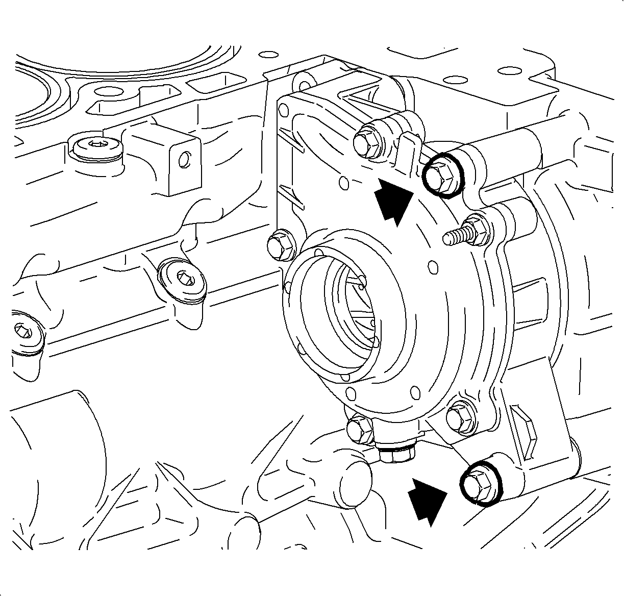
Important: Prior to installing the water pump, read the entire procedure. Pay special attention to avoid part damage and to ensure proper sealing.
Tighten
Tighten the water pump bolts to 25 N·m
(18 lb ft).
Tighten
Tighten the water pump sprocket to water pump bolts
to 10 N·m (89 lb ft).
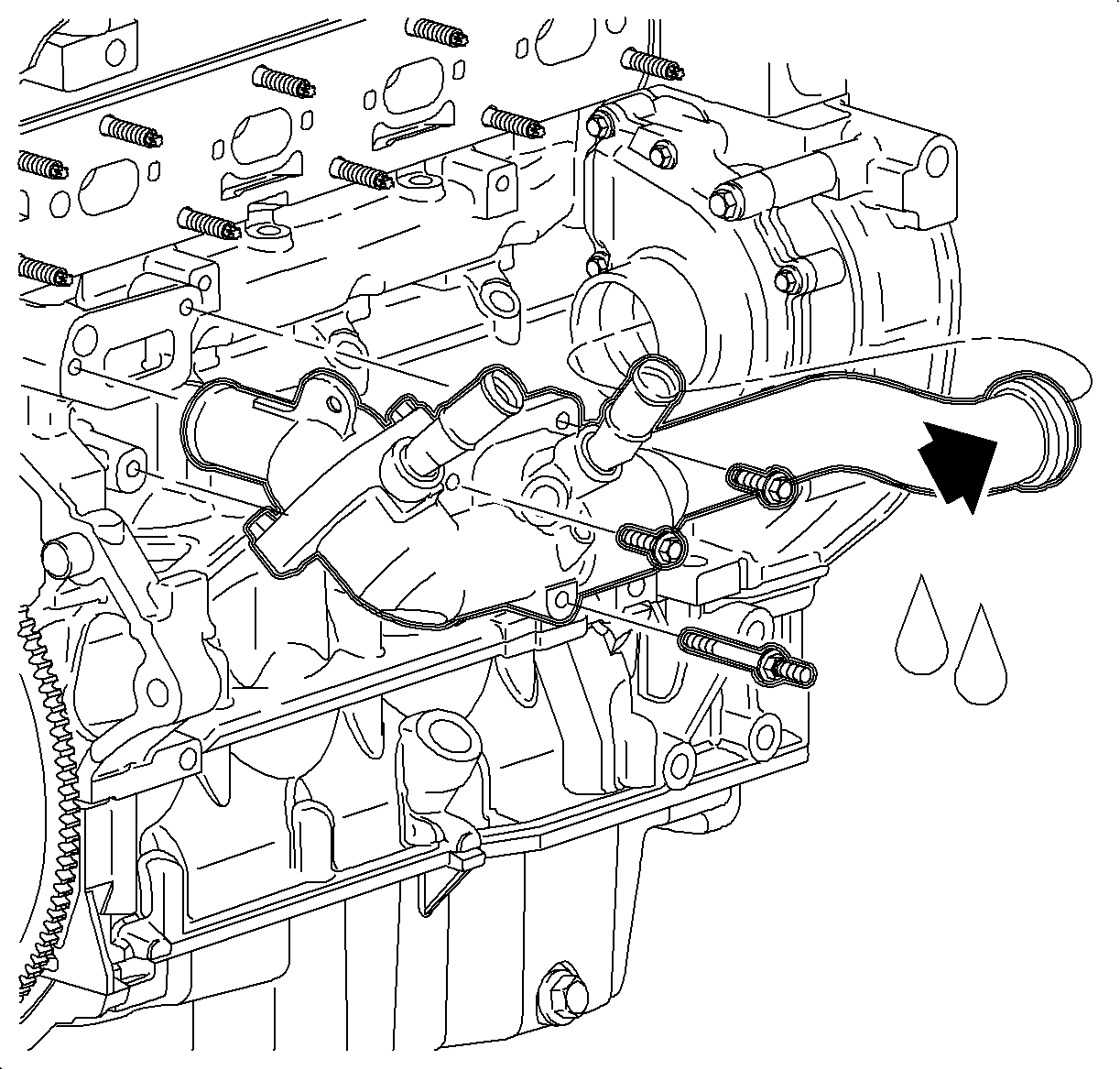
Tighten
Tighten the thermostat housing to block bolts to
10 N·m (89 lb in).


Tighten
Tighten the battery terminal bolts to 17 N·m
(13 lb ft).
Water Pump Replacement L81
Tools Required
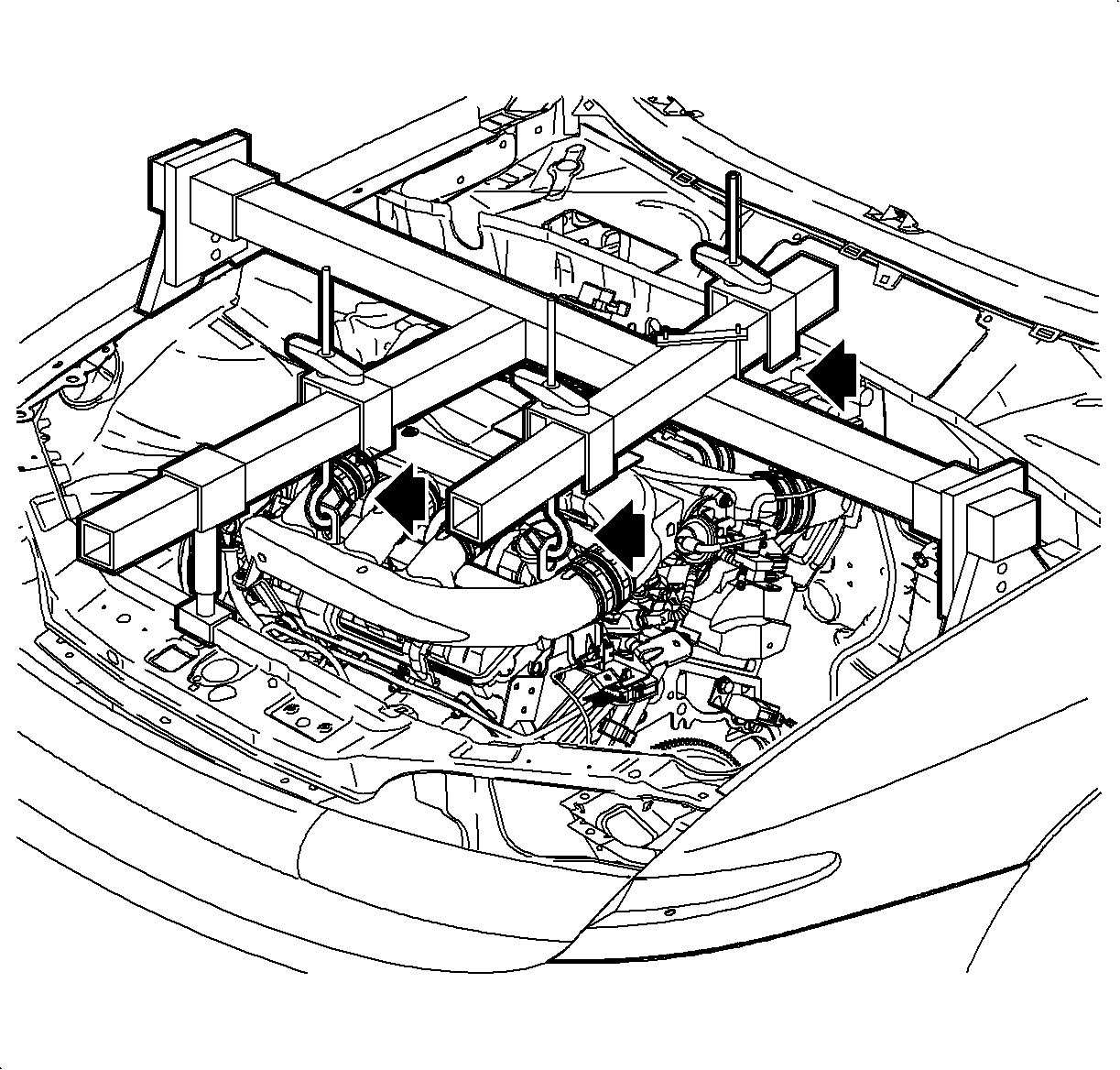
SA9105E Engine Support Fixture (3 Bar)
Removal Procedure
- Disconnect the negative battery cable.
- Remove the air cleaner inlet duct from the throttle body.
- Raise and support the vehicle.
- Remove the left front wheel.
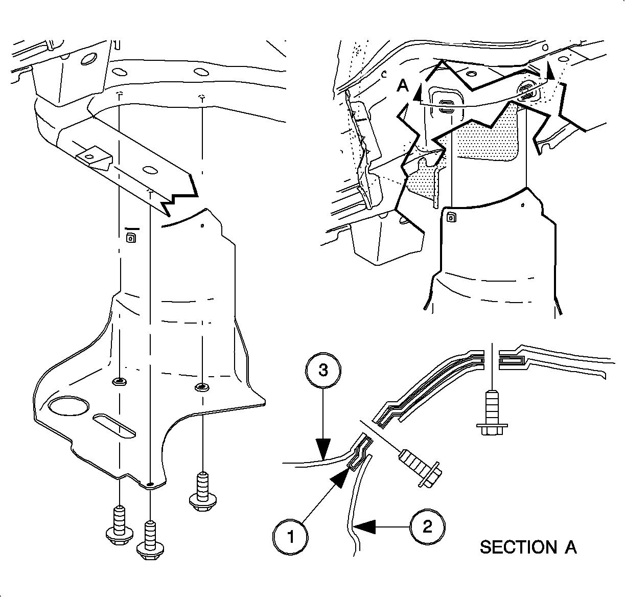
- Remove the splash shield bolts.
- Remove the splash shield.
- Lower the vehicle.
- Loosen the water pump pulley and power steering pump pulley attachment bolts. The accessory drive belt tension provides resistance to enable the loosening of the water pump pulley bolts. Do not remove the bolts at this time.
- Install the SA9105E to support the engine weight.
- Remove the accessory drive belt. Refer to Drive Belt Replacement .
- Release the plastic retaining tabs on the wiring harness channel on the front cover and remove the cover.
- Note the wiring harness routing.
- Remove the wiring harness from the channel.
- Remove the water pump pulley bolt.
- Remove the water pump pulley.
- Remove the power steering pump pulley bolts.
- Remove the power steering pump pulley.
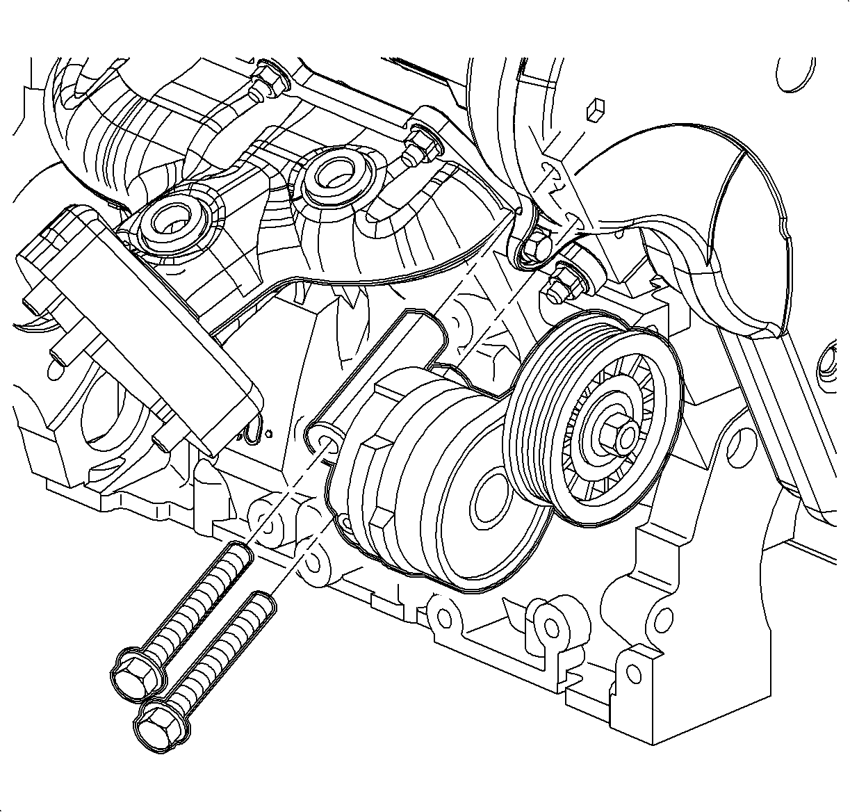
- Remove the accessory drive belt tensioner bolts.
- Remove the accessory drive belt tensioner.
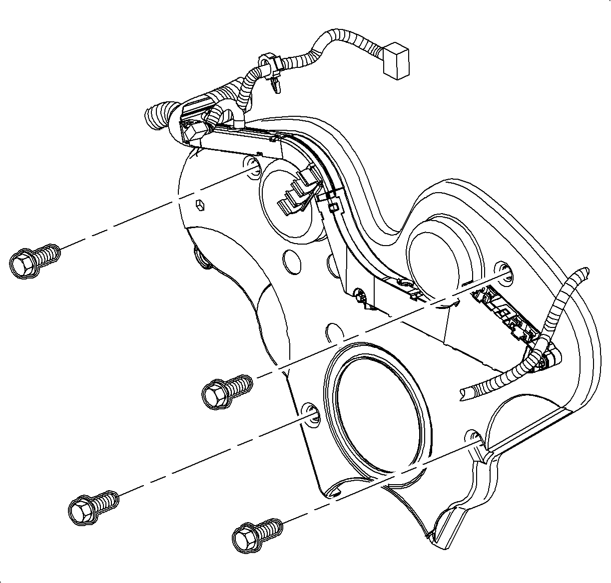
- Remove the front timing belt cover bolts.
- Remove the front timing belt cover.
- Inspect the sealing strip on the outer edge of the front timing belt cover for cracks and/or tears.
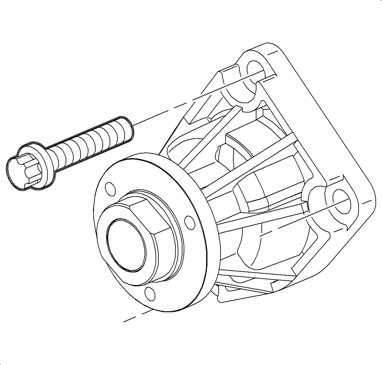
- Remove the water pump and O-ring seal.
Caution: Refer to Radiator Cap Removal Caution in the Preface section.
Caution: Refer to Vehicle Lifting Caution in the Preface section.
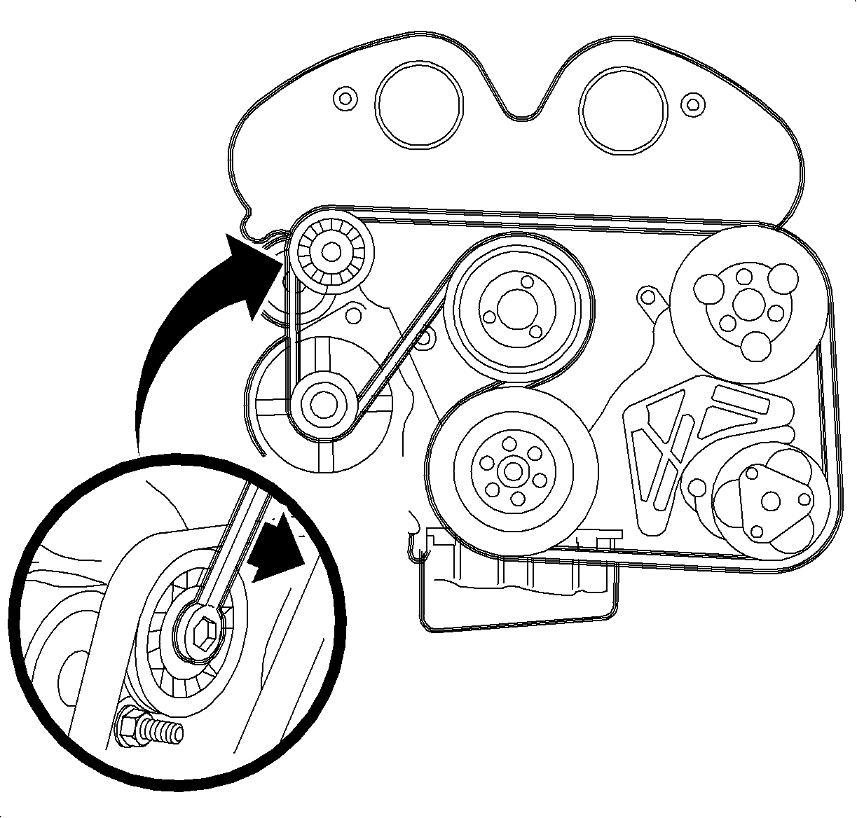
Important: Removal of the accessory drive belt requires removal of the right front engine mount.
Important: Use caution when releasing the retaining tabs to reduce the risk of breakage when removing the wiring harness cover.
Installation Procedure
- Install the new water pump O-ring seal.
- Install the water pump.
- Install the water pump bolts.
- Install the front timing belt cover.
- Install the front timing belt cover bolts.
- Install the accessory drive belt tensioner.
- Install the accessory drive belt tensioner bolts.
- Install the power steering pump pulley and water pump pulley.
- Install the power steering pump pulley and water pump pulley bolts.
- Snug the power steering pump pulley and water pump pulley bolts. The bolts will be tightened when the accessory drive belt is installed.
- Route the wiring harness into the wiring harness channel.
- Install the wiring harness channel.
- Install the wiring harness channel extension to the right lower side of the wiring harness channel.
- Install the accessory drive belt. Refer to Drive Belt Replacement .
- Tighten the water pump pulley and power steering pump pulley bolts.
- Remove the SA9105E .
- Raise and support the vehicle.
- Install the splash shield.
- Install the splash shield bolts. Tighten the splash shield bolts until seated. Do not strip the bolts.
- Install the right front wheel.
- Lower the vehicle.
- Install the air resonator inlet duct to the throttle body.
- Reconnect the negative battery cable.

Tighten
Tighten the water pump bolt to 25 N·m (18 lb ft).

Tighten
Tighten the front timing belt cover bolt to 8 N·m (71 lb in).

Tighten
Tighten the belt tensioner bolts to 40 N·m (30 lb ft).

Tighten
| • | Tighten the water pump pulley bolt to 8 N·m (71 lb in). |
| • | Tighten the steering pump pulley bolt to 20 N·m (15 lb ft). |


Tighten
Tighten the splash shield bolts to 5 N·m (44 lb in).
Tighten
Tighten the battery terminal bolts to 17 N·m (13 lb ft).
