Description and Operation
The Saturn cooling system uses a pressured coolant surge tank and doesn't have a reservoir or overflow bottle. All components of the cooling system are filled from the surge tank and no additional bleeding is necessary.
At cold start-up, the thermostat will be in the closed position. The engine water pump will pump coolant through the cylinder head and block as well as the throttle body. Coolant is also pumped through the heater inlet hose to the heater water pump. The heater water pump assists the engine water pump by increasing the coolant flow rate through the heater core. Coolant returns from the heater core through the heater outlet hose to the engine block. Any air in the engine block or heater core is carried by coolant to the surge tank through the head degas hose. Coolant then flows from the surge tank back to the engine block through the return hose.
When the coolant returns to the engine block, it flows over the thermostat element. When the coolant temperature reaches 90°C (194°F), the thermostat will begin to open. The coolant will flow through the upper radiator hose, through the radiator, and back to the engine through the lower radiator hose. Any air in the radiator is carried by coolant to the surge tank through the radiator degas hose.
If the coolant temperature exceeds 105°C (221°F) at engine shutdown, the heater water pump will be enabled for several minutes. The heater water pump will pump coolant in a loop through the engine and to the radiator while the cooling fans run to reduce the coolant temperature.
There are two cooling fans - a pusher and a puller. The fans run together at three different voltage levels to create three speeds or stages.
Cooling Fan Logic
| • | Low speed - both fans in series - 6 volts each. |
| • | Medium speed - both fans in parallel with resistor in series - 9 volts each. |
| • | High speed - both fans in parallel without resistor - 12 volts each. |
The fan speed selected is based on coolant temperature or A/C system high side pressure.
Low Speed
| • | Enabled if coolant temperature exceeds 96° C (204° F) or A/C system pressure exceeds 1199 kPa (174 psi) high side. |
| • | Disabled if coolant temperature goes below 92° C (198° F) and A/C system pressure goes below 799 kPa (116 psi) high side. |
Medium Speed
| • | Enabled if coolant temperature exceeds 99° C (210° F) or A/C system pressure exceeds 1695 kPa (246 psi) high side. |
| • | Back to Low speed if coolant temperature goes below 97° C (207° F) and A/C system pressure goes below 1399 kPa (203 psi) high side. |
High Speed
| • | Enabled if coolant temperature exceeds 102° C (216° F) or A/C system pressure exceeds 2398 kPa (348 psi) high side. |
| • | Back to Medium speed if coolant temperature goes below 100° C (212° F) and A/C system pressure goes below 2198 kPa (319 psi) high side. |
Coolant Surge Tank
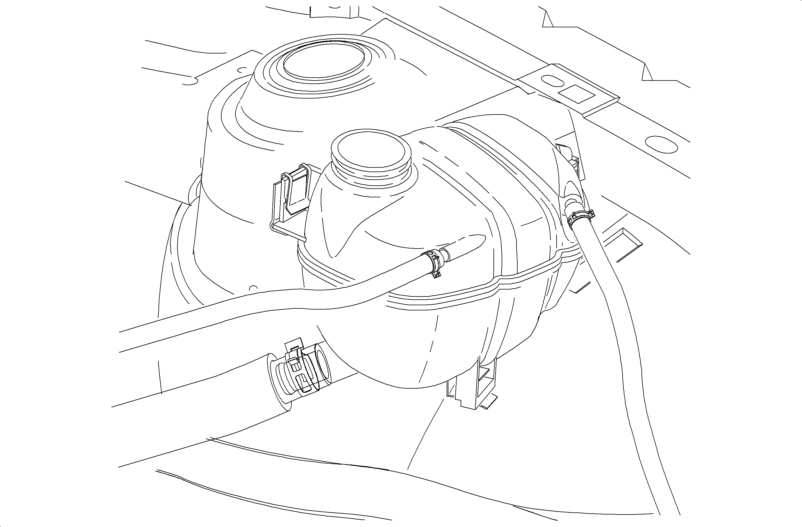
The coolant surge tank is made of molded plastic. It incorporates a low coolant sensor. This sensor is designed to signal low coolant level within the reservoir through a light on the dash. A magnetic float assembly moves up and down with the coolant. An electrical switch is held in the closed position by the magnetic float. When the coolant level drops below a pre-determined point, the float assembly drops and opens the switch which triggers the low coolant light. When properly filled, the coolant level on a cold engine should be level with the surge tank seam.
Engine Cooling Fan - L61
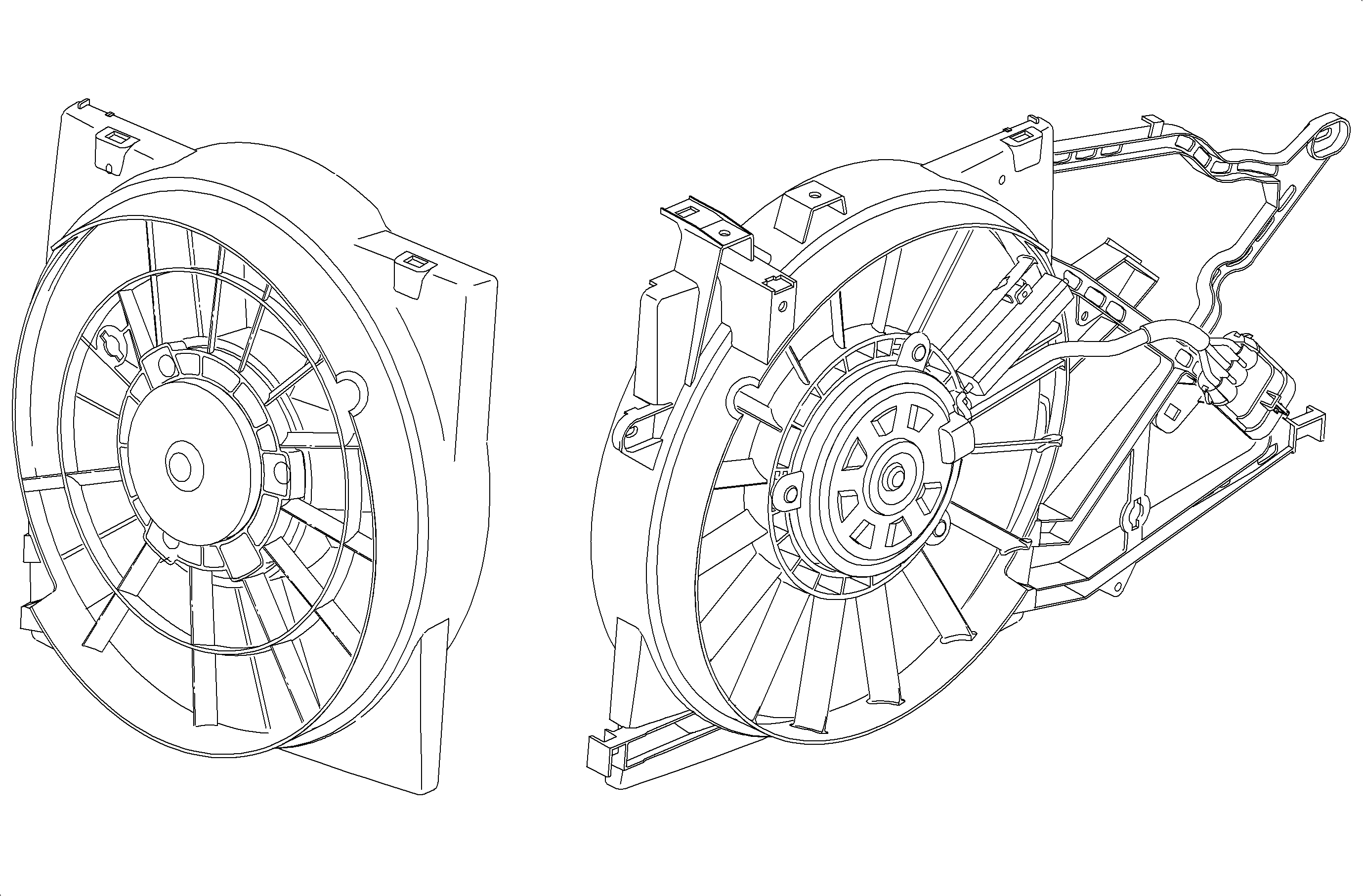
A cooling fan control module is used by the PCM to control engine cooling fan operation. The engine cooling fans are turned ON or OFF by the PCM dependent upon engine coolant temperature, or A/C system pressure. Under high ambient conditions, the fans may run for several minutes after the key is turned OFF.
Engine Cooling Fans - L81

A fan control module is used by the ECM to control engine cooling fan operation. The engine cooling fans are turned ON or OFF by the ECM dependent upon engine coolant temperature or A/C system pressure.
Under high ambient conditions, the cooling fans and heater water pump may run for several minutes after the key is turned OFF.
Radiator
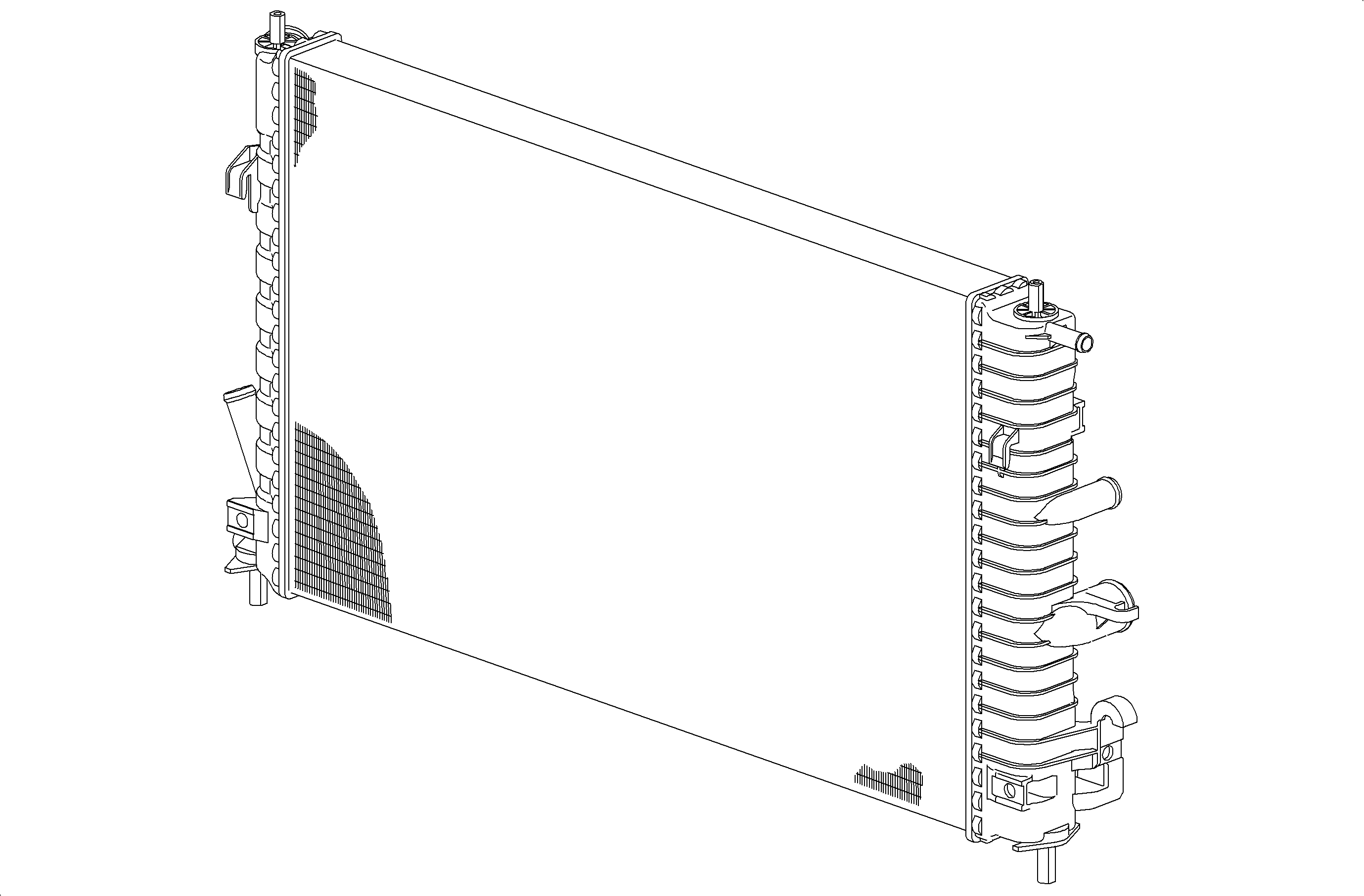
A cross-flow radiator is used. Tanks on this type of radiator are located to the right and left of the core. All service radiators have oil coolers with inlet/outlet fittings for transaxle fluid circulation.
Cooling System
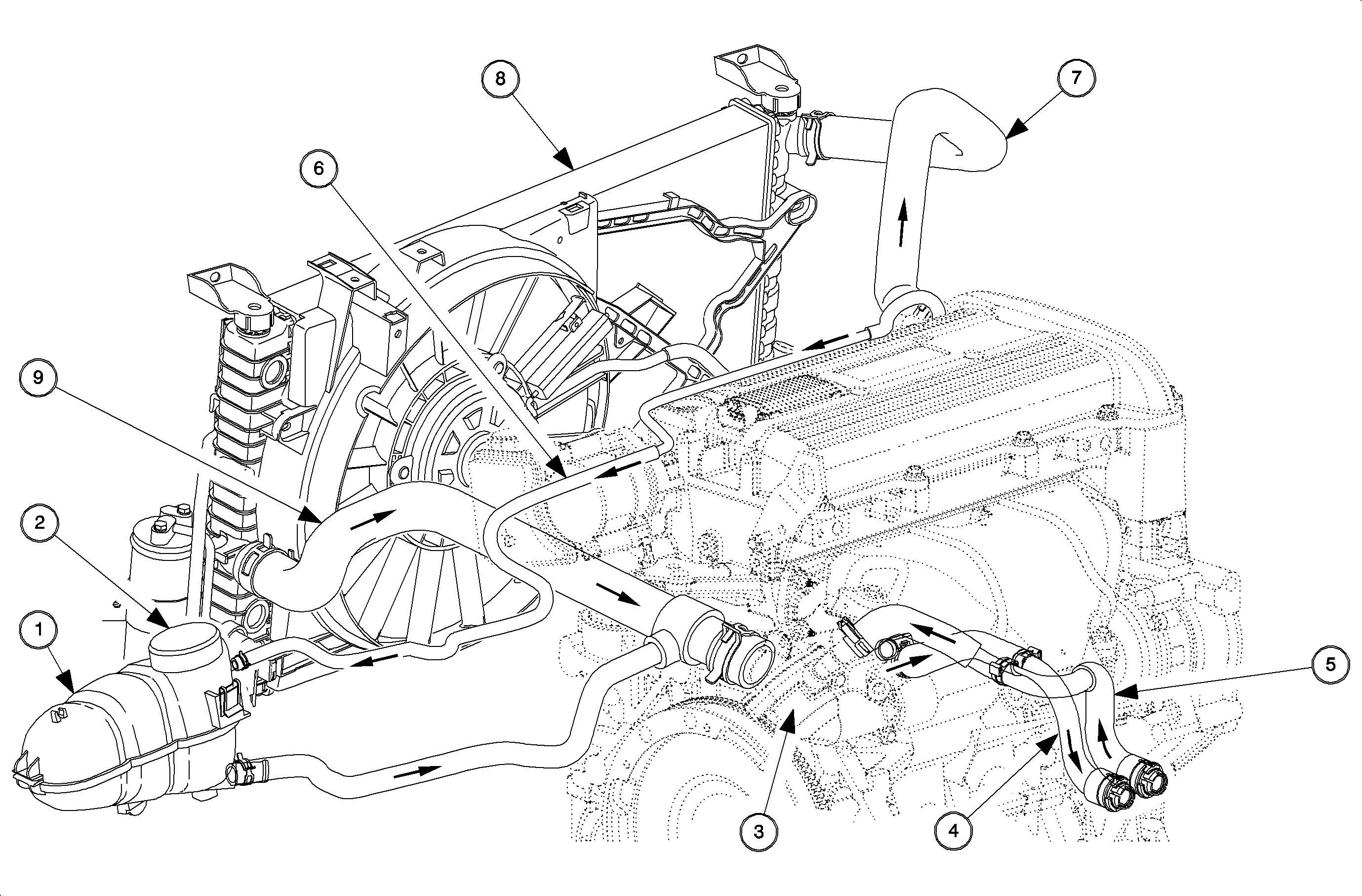
Insert Legend
The Saturn cooling system uses a pressurized coolant surge tank and does not have a reservoir or overflow bottle. All components of the cooling system are filled from the surge tank and no additional bleeding is necessary.
At cold start-up, the thermostat will be in the closed position. The engine water pump will pump coolant through the cylinder block and head. Coolant is also pumped through the heater inlet hose to the heater core. Coolant returns from the heater core through the heater outlet hose to the engine block. Any air in the engine block or heater core is carried by coolant to the surge tank through the head degas hose. Coolant then flows from the surge tank back to the engine block through the return hose portion of the lower radiator hose.
When the coolant returns to the engine block, it flows over the thermostat element. When the coolant temperature reaches 90°C (194°F), the thermostat will begin to open. The coolant will flow through the upper radiator hose, through the radiator, and back to the engine through the lower radiator hose.
Heater Water Pump - L81
The heater water pump is located on the back side of the engine. The pump is rubber mounted to the engine block and is in series with the heater core inlet hose. One purpose of the heater water pump when the key is ON is to provide a quick warm-up of the heater core and the cockpit area. Another purpose of the pump is to increase the flow of engine coolant through the engine and heater core, and to prevent coolant boil over after engine shutdown, by cycling coolant through the system when the engine is turned OFF. This water pump runs whenever the ignition is turned OFF under high coolant temperature conditions. At ignition OFF, the pusher and puller fans run in series, 6 volts each, along the heater water pump for several minutes. The heater water pump and mounting bracket are serviced as an assembly.
