Removal Procedure
- Disconnect the negative battery cable.
- Remove the air cleaner assembly.
- Disconnect the intake air temperature (IAT) sensor electrical connection.
- Disconnect the crankcase vent hose from the camshaft cover.
- Remove the air inlet hose.
- Disconnect the following electric connections:
- Remove the engine harness from the top of the manifold and disconnect the harness from under the intake manifold.
- Remove the fuel pressure regulator vacuum pipe.
- Disconnect the EVAP purge solenoid hose from the throttle body.
- Unclip the throttle cable and the brake booster pipe retaining clips.
- Remove the throttle cable from the throttle body linkage cam.
- Disconnect the brake booster vacuum pipe at the brake booster.
- Remove the oil level indicator tube.
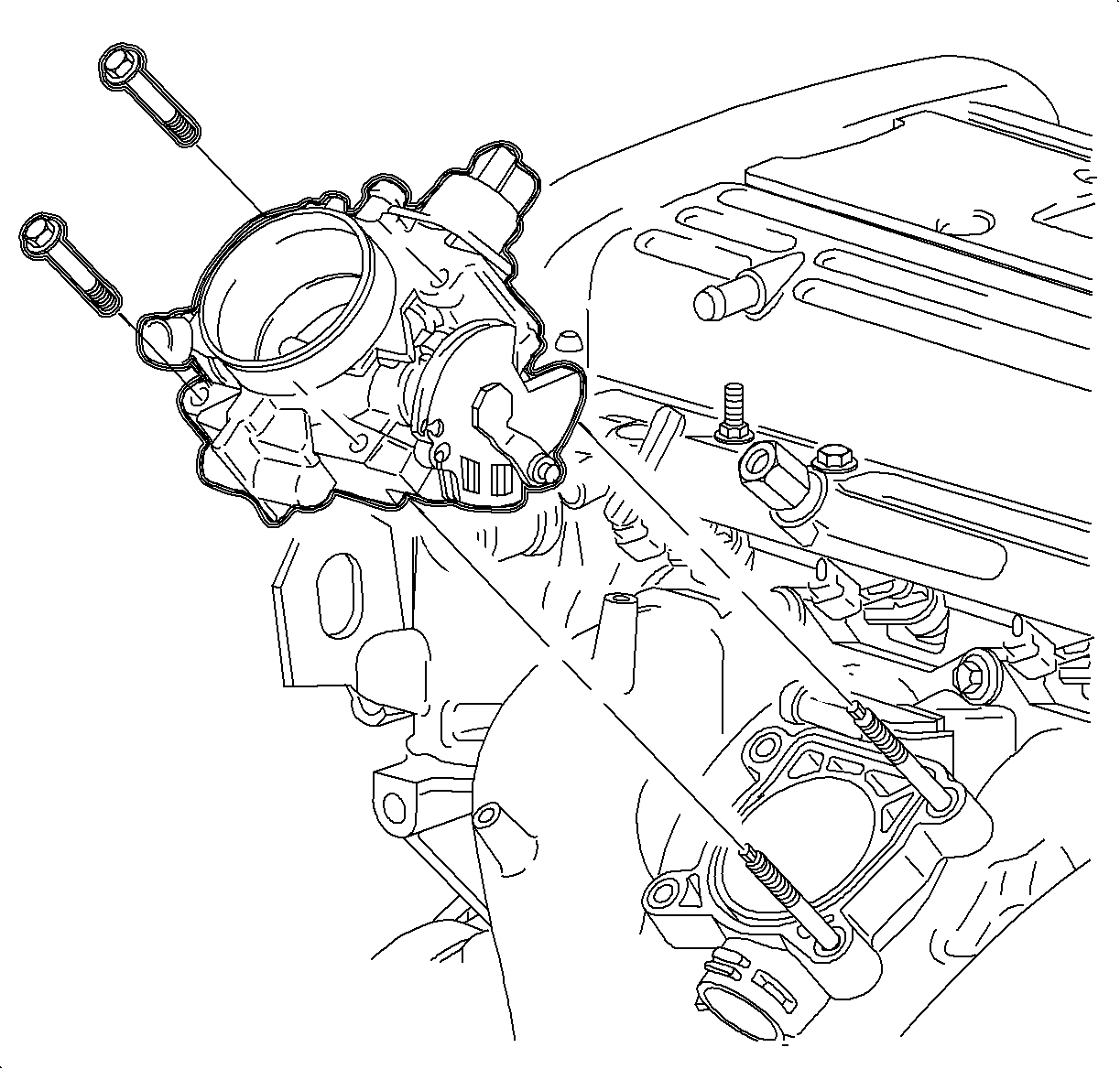
- Remove the throttle body bolts and nuts. Secure the throttle cable bracket away from the engine.
- Remove the throttle body.
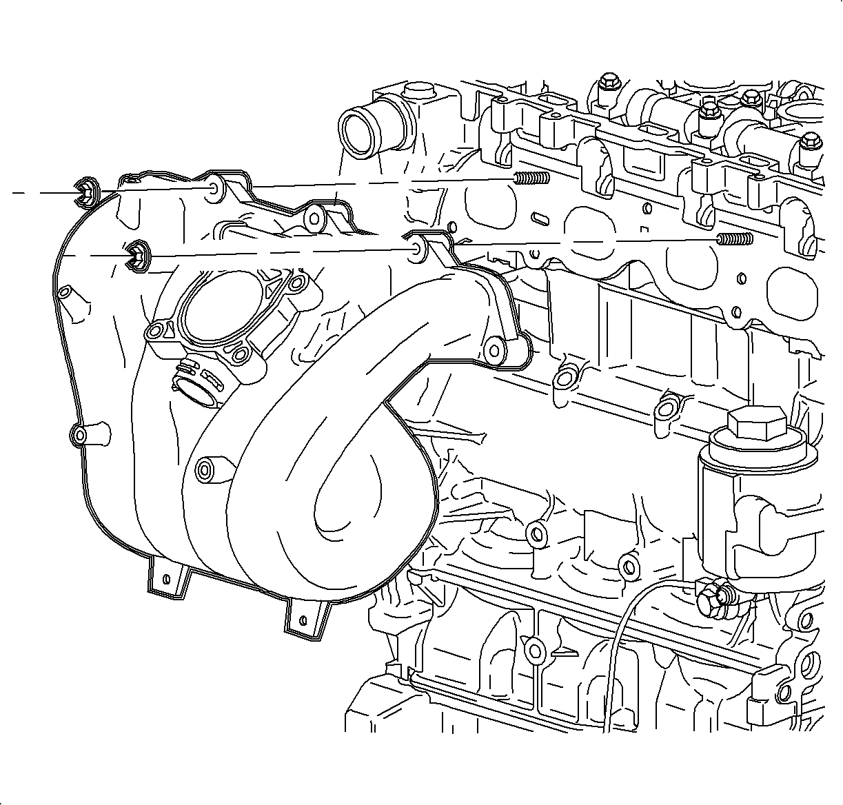
- Remove the intake manifold bolts and nuts.
- Remove the intake manifold and gasket assembly.
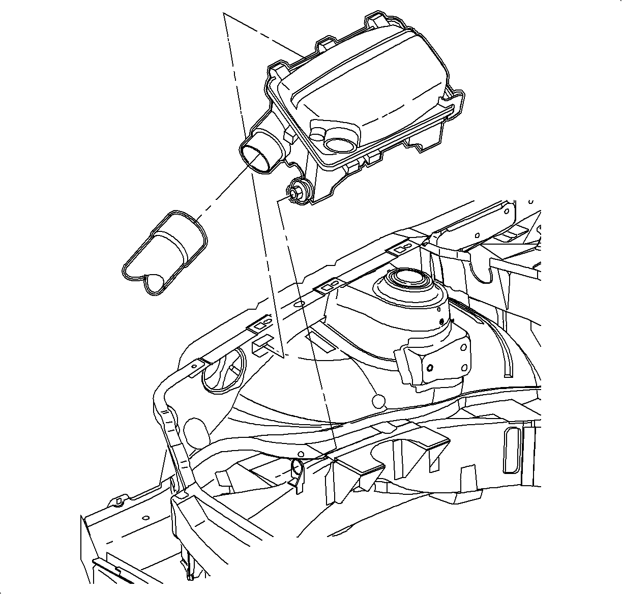
Notice: Never attempt to remove the intake manifold from a hot engine, allow the engine to cool to ambient temperature. The intake manifold is made of a composite plastic and can be damaged if it is removed when the engine is hot.
| 6.1. | Idle air control (IAC) |
| 6.2. | Throttle position sensor (TPS) |
| 6.3. | Manifold absolute pressure (MAP) |
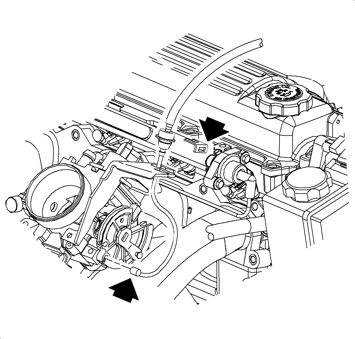
Important: Do not bend the throttle cable.
Installation Procedure
- Install the intake manifold gasket assembly.
- Install the intake manifold onto the cylinder head.
- Install the intake manifold bolts and nuts.
- Install the throttle body seal ring into the seal ring groove.
- Install the throttle body onto the intake manifold.
- Install the throttle cable bracket onto the throttle body studs.
- Install the throttle body nuts and bolts.
- Install the oil level indicator tube and the tube fastener.
- Connect the brake booster vacuum pipe at the brake booster.
- Install the throttle cable and the brake booster pipe into the retaining clips.
- Connect the throttle cable to the throttle body linkage cam.
- Connect the EVAP purge solenoid hose to the throttle body.
- Install and connect the fuel pressure regulator vacuum pipe to the throttle body and regulator.
- Route the engine wire harness on top of the engine and connect the additional harness clips under the intake manifold.
- Install the harness bracket bolts.
- Connect these electrical connections:
- Install the air inlet hose to the throttle body.
- Connect the crankcase vent hose to the camshaft cover.
- Connect the intake air temperature (IAT) electrical connection.
- Install the air cleaner assembly.
- Connect the negative battery cable.

Important: The intake manifold gasket assembly may be reused if the seal rings are not damaged.
Tighten
Tighten the intake manifold-to-cylinder head bolts to 10 N·m(89 lb
in).

Important: The throttle body seal ring may be reused if not damaged or cut.
Tighten
Tighten the throttle body bolts to 10 N·m(89 lb in).
Tighten
Tighten the oil level indicator tube-to-intake manifold bolt to 10 N·m(89 lb
in).

Important: Do not bend the throttle cable.
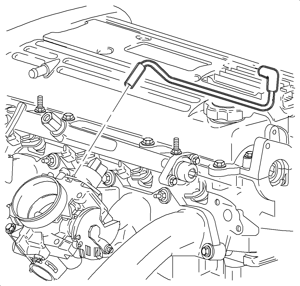
Tighten
Tighten the engine harness bracket bolts to 10 N·m(89 lb in).
| 16.1. | Manifold absolute pressure (MAP) |
| 16.2. | Throttle position sensor (TPS) |
| 16.3. | Idle air control (IAC) |

Tighten
Tighten the battery terminal bolts to 17 N·m(13 lb ft).
