Energizing the Fuel Pump
All of the fuel system tests will require operation of the fuel pump to measure
pressure, evaluate pressure decay, or perform the pressure at the calibrated flow
tests.
Although the fuel pump can be controlled with the ignition, this is fairly awkward
since:
| • | The pump is only energized for 2-3 seconds at Key On. You
must wait for 10 seconds after Key Off before the pump can be powered again. |
| • | Some tests are run with the vehicle on a hoist with the control of the
pump under the car required, and |
| • | Pressure at the flow tests requires the pump to run for 10-20 seconds. |
The scan tool provides control of the fuel pump at the technicians finger-tips.
The tool will run the pump for 30 seconds after the ON command. This timer
will then shut the pump OFF.
Important: Once the fuel pump is commanded ON with the
scan tool it will be energized for 30 seconds before it times out and returns
to the OFF status. Do not leave the vehicle unattended while running any of the system
tests with the pump ON.
The scan tool also controls the pulsing of the injectors and pressurizing the
system during the Injector Balance Test 8.
Operating the Fuel Pump/Injector Balance Test
Control of the fuel pump and injector are under the Special Functions menu.
| • | Once in Special Functions, select Powertrain. |
Fuel System Testing
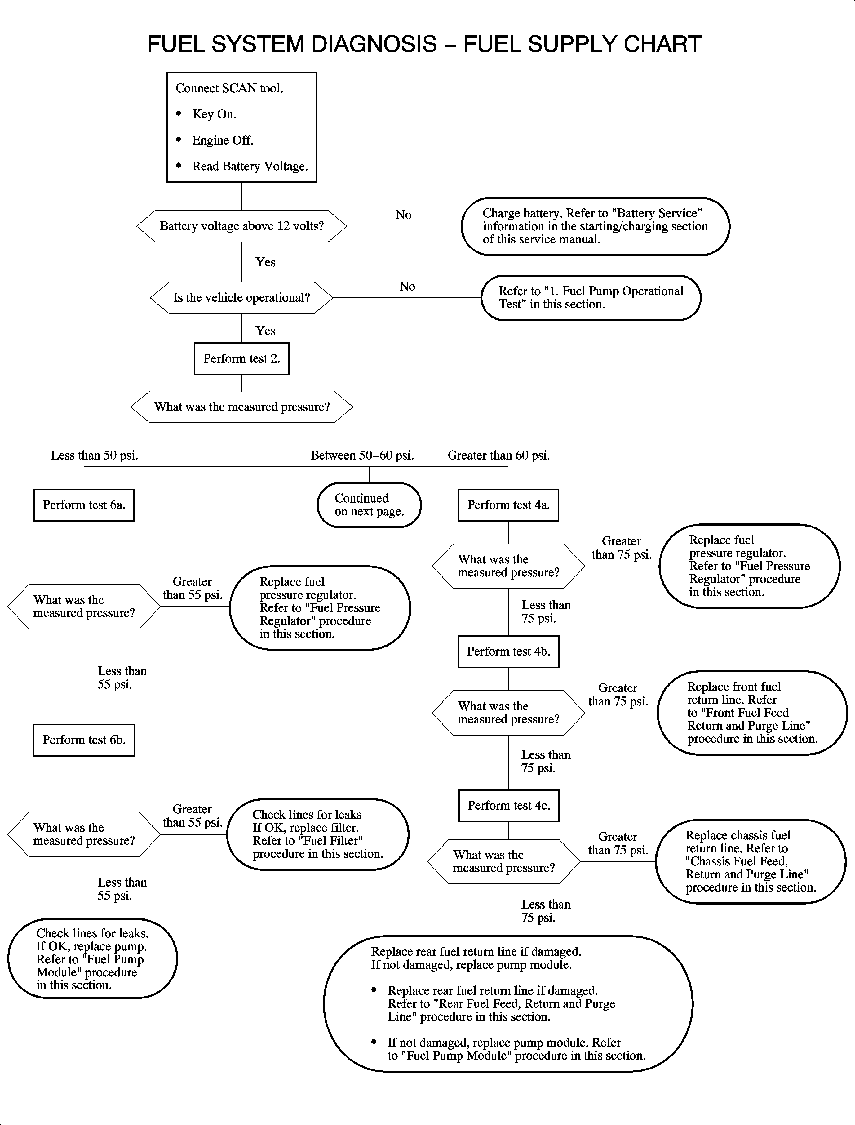
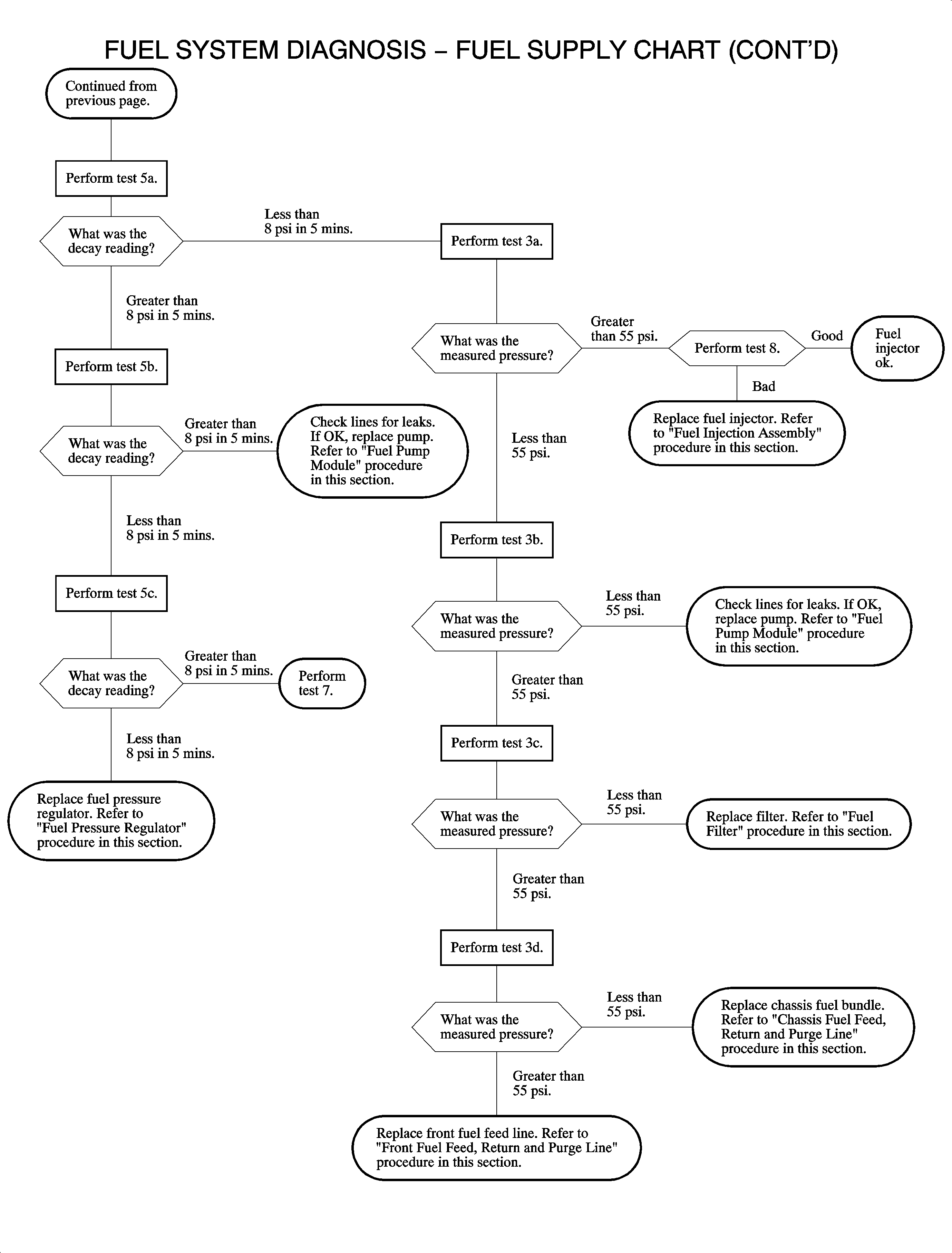
The fuel system tests outlined in the fuel system diagnostic flow chart and
detailed procedures (Tests 1-8) provide a systematic approach to determining
whether the fuel system, from the fuel pump to the fuel injectors, is functioning
as intended.
For the engine to operate as designed, the fuel supply system must deliver fuel
at the proper pressure with adequate volume and maintain pressure after the engine
and fuel pump are turned OFF.
In addition, the fuel injectors must deliver the precise quantity of fuel at
exactly the correct intervals with no leakage of fuel when the injector is turned
OFF.
The battery of tests outlined in the Fuel System Diagnosis flow chart are designed
to evaluate all the performance characteristics. Symptoms or complaints related to
the fuel system include:
| • | No start (hot and/or cold) |
| • | Poor acceleration, stalling, stumbling |
Diagnostic trouble codes associated with fuel supply problems include DTC P0171
and P0172.
Important: The performance of the fuel pump (pressure
and flow) is very dependent on supply voltage. The voltage must be above 12 volts
when running any of the diagnostic tests. Published test specifications cover the
range of system operation from 12-14 volts, but are biased towards the
lower voltages (12-12.7 volts) since all tests are run with the engine
OFF. All accessory loads should be OFF when running any tests (DRL's, interior lights,
radio, etc.) to provide maximum available voltage for the tests. If voltage is below
12 volts, the battery must be charged before running the tests.
Test 1 - Fuel Pump Operational Test
Test to establish whether the fuel pump is operating and providing fuel to the
injectors.
Test 2 - Fuel Pressure at Idle (or engine Off) Test
Basic integrity test of the fuel system to determine whether the regulated operating
pressure is achieved under low load conditions.
Test 3 - Fuel Pump Flow/Pressure Test
Actually a series of 4 tests (3A, 3B, 3C, and 3D) to determine if fuel
pressure is within operating limits while simulating the flow demand of the engine
running at wide open throttle. These tests are run with the engine OFF and provide
a means, based on testing at 4 points in the system, of determining if the
fuel feed line, fuel pump, and the fuel filter are operating to design specifications.

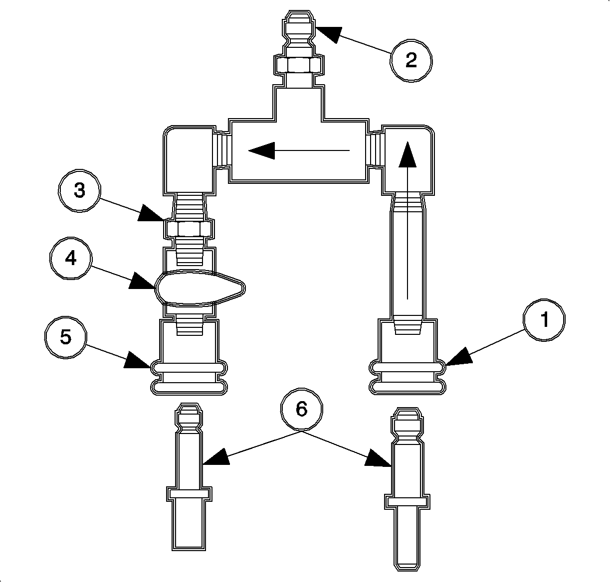
The testing is performed using the SA9127E-7
fuel flow/pressure test adapter which incorporates a precision orifice
to meter 50 liters/hr at a delivery pressure of 380 kPa (55 psi)
for the 2.2 liter (L61).
The flow/pressure adapter consists of:
| • | (1) Female, quick connect inlet fitting |
| • | (2) Male, quick connect fitting (to pressure gage) |
| • | (3) Precision orifice fitting |
| | Important: The flow control valve rotates 90 degrees
from the ON position, with the handle in-line with the fitting, to OFF.
|
| • | (4) On/Off flow control valve |
| • | (5) Female, quick connect outlet fitting. |
| • | (6) Adapter fittings - male 10 mm (3/8 in) and 8 mm
(5/16 in) quick-connects for fuel lines to 6 mm (1/4 in) quick-connects
on the test adapter. |
It is connected with the inlet side to the fuel feed, the outlet side to the
fuel return (or drain), and the gage port to the pressure gage or cap. The ON/OFF
control valve provides a means to control the fuel flow for pressure and leakdown
testing.
The test criteria is the fuel pressure read while the fuel pump is energized.
Refer to Energizing the Fuel Pump, with the engine OFF. If the pressure measured is
within specification then the fuel supply is capable of meeting all volume requirements
of the engine.
Test 4 - Fuel Pressure Regulator and Return Lines Integrity Test
Actually a series of 3 tests (4A, 4B, and 4C) to determine if the fuel
pressure regulator or fuel return lines are operating properly.
Test 5 - Fuel System Pressure Leakdown (Decay) Test
Actually a series of 3 tests (5A, 5B, and 5C) to determine if the fuel
system will maintain pressure after the engine and fuel pump are shut-off. Fuel pressure
must be maintained after shut-off to ensure quick restarts and prevent fuel vapor
from forming at the fuel rail, causing hard or extended cranks. The tests are arranged
to allow isolating the problem components or area by evaluating the components in
sequence.
Test 6 - Fuel System Pressure Test
Actually a series of 2 tests (6A and 6B) used to determine the cause
of low fuel pressure. The 2 tests are designed to isolate faulty components,
such as the fuel pressure regulator, fuel pump, or fuel filter. This is accomplished
by measuring pressure using the SA9127E-7
fuel flow/pressure adaptor in 2 locations.
Test 7 - Fuel Injector(s) Tip Leakage Test
This test determines if fuel injectors are leaking fuel into the intake system.
Leaking fuel injectors can cause problems with extended cranks, hard starting, and
rich running conditions (DTC P0172).
Test 8 - Fuel Injector Balance Test
This test determines if fuel injectors are metering an equal quantity of fuel
when they are commanded open. By measuring fuel pressure drop during a timed cycle
of opening each injector, a relative evaluation of each injectors flow rate is made.
This test is designed to identify injectors with significant differences in flow rate
but will not identify problems with an injector flow pattern (e.g., improperly sized
spray cone, non-uniform spray cone (pattern), mis-directed spray cone, etc.)
Fuel System Pressure Relief
Tools Required
SA9127E Gage Bar Set
Caution: Refer to Relieving Fuel Pressure Caution in the Preface section.
Prior to servicing any fuel system components, such as the fuel rail, injectors,
filter, pressure regulator, fuel tank, fuel pump module, etc., any pressure built
up in the system must be relieved. There are 2 preferred methods:
- Start and run vehicle then disable the fuel pump with the scan tool.
This method is the cleanest since no fuel, under pressure, will be present at
any fitting or connection that needs to be serviced.
This method is preferred when removing any components of the fuel system that
require disconnecting fuel lines. If performance tests are to be run on the system
underhood, procedure 2 will be preferable since the SA9127E
will also be required for the testing.
This method is also preferable to disconnecting the fuel pump relay since no
DTCs will be set and there is no concern about voltage spikes to the ECM if the relay
should be installed with the key ON.
| 1.1. | Connect the scan tool and start the vehicle. |
| 1.2. | Turn the scan tool ON and locate Special Functions. |
| 1.6. | Command the fuel pump OFF. |
| 1.7. | The engine will die in 3-5 seconds. Turn the key OFF, and
proceed with component removal/installation. |

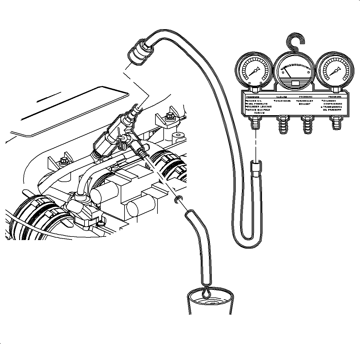
- Bleed pressure at the service test port.
This method will require
collection of fuel as pressure is relieved. Use of a suitable container is required.
Caution: Refer to Gasoline/Gasoline Vapors Caution in the Preface section.
| 2.1. | Locate the service test port on the fuel rail and remove the protective cap. |
| 2.2. | Connect the gage bar 53476 to the fuel gage pressure adapter 309725
using a flexible hose from the SA9127E
. |
| 2.3. | Make sure the needle valve on the pressure adapter is closed (OFF). |
| | Notice: Do not use any tools to tighten the adapter to the fuel line pressure port.
If the adapter will not seal with finger tightening, then the seal is defective or
damaged and needs to be replaced. Excessive torque on the adapter will damage the
fuel line test port.
|
| 2.4. | Connect the pressure adapter to fuel line test port. |
| 2.5. | Route the drain hose from the pressure adapter into a suitable container
or route the fuel back to the fuel tank. |
| 2.6. | Open the valve on the pressure adapter and bleed off the pressure and
fuel. |


