
EVAP System Operation
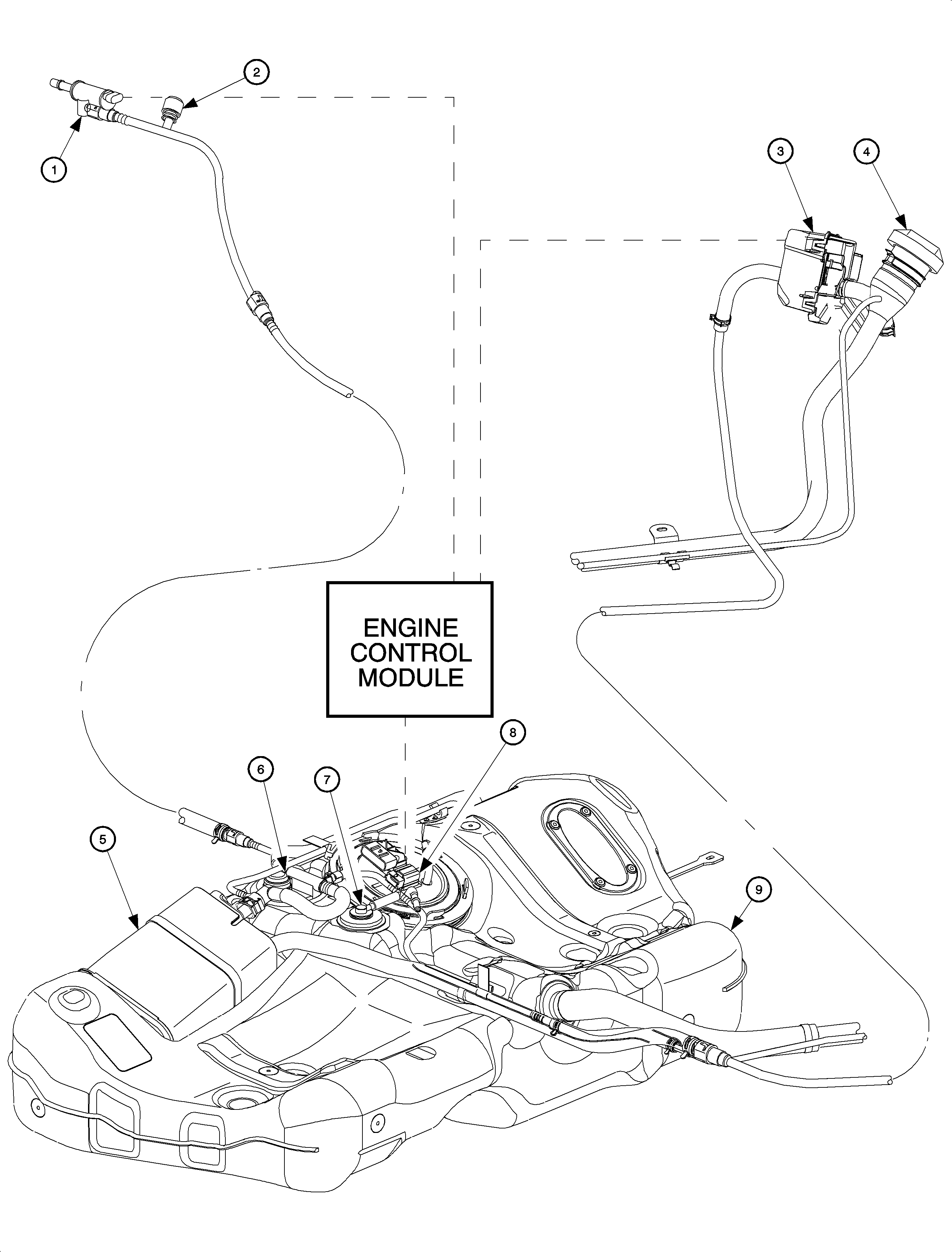
The enhanced EVAP system is used to limit unburned fuel vapors (hydrocarbons) from escaping into the atmosphere. Since fuel evaporation in the fuel tank is a normal process, it is necessary to accumulate the unburned fuel vapors so they can be purged into the intake manifold for combustion. The EVAP system consists of:
- EVAP purge solenoid (located on the side of the air box)
- EVAP service port (located underhood in the EVAP purge line near the right strut tower identified by a green colored cap)
- EVAP vent solenoid (located near fuel filler neck)
- Fuel cap
- EVAP canister (located on top of fuel tank)
- Fill limit vent valve (FLVV) - Service only as part of fuel tank
- Grade vent valve (GVV) - Service only as part of fuel tank
- Fuel tank pressure sensor (located on top of the fuel tank)
- Fuel tank
When fuel from the fuel tank evaporates, the vapors flow though the fuel level vent valve (FLVV), located on the top of the fuel tank, to the EVAP canister. The EVAP canister is an active carbon fiber storage container that collects fuel vapors and prevents them from entering the atmosphere. The EVAP canister is vented to the atmosphere through the EVAP vent solenoid. The EVAP vent solenoid is a normally open valve that only closes during parts of the EVAP diagnostic test.
When the PCM goes into purge mode (drawing fuel vapors into the intake manifold), it will pulse width modulate the EVAP purge solenoid by intermittently grounding the EVAP purge solenoid circuit. As the EVAP purge valve opens and closes, ported vacuum draws fuel vapors from the EVAP canister.
EVAP System Diagnostics
The PCM monitors the following EVAP system electrical components for low and high voltage faults.
| • | Fuel tank pressure sensor |
| • | EVAP purge solenoid |
| • | EVAP vent solenoid |
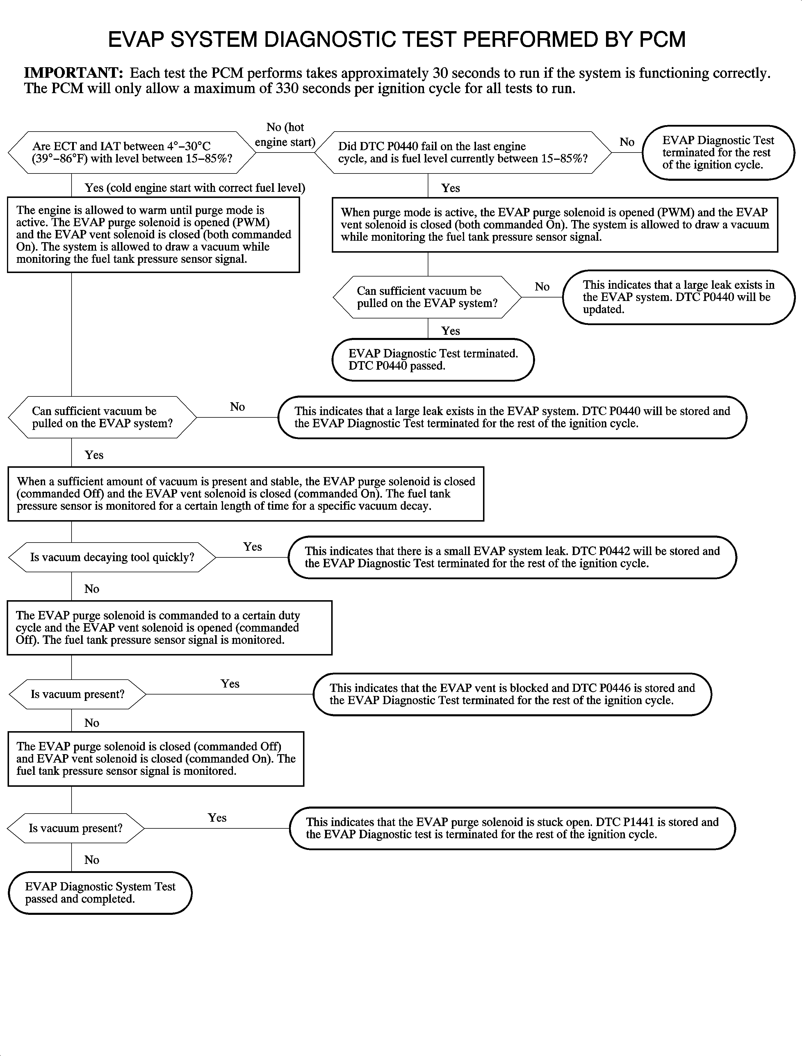
As part of the On-board diagnostics second-generation (OBD II) requirements, the government mandates that all automobile manufactures detect a 0.020 inch or greater diameter leak in the EVAP system. To comply, the PCM monitors the EVAP system for large and small leaks and whether the EVAP purge and vent solenoid valves are stuck closed or open.
Important: The following flowchart consists of a series of tests run by the PCM which describes the entire EVAP DIAGNOSTIC TEST. Each step the PCM performs is dependent on the accuracy of the fuel tank pressure sensor. The FUEL TANK PRESS. SENSOR reading on Scan tool with ignition On, engine off and fuel cap removed should read between 2.35 and 2.85 volts.
