Accelerator Pedal Position (APP) Sensor
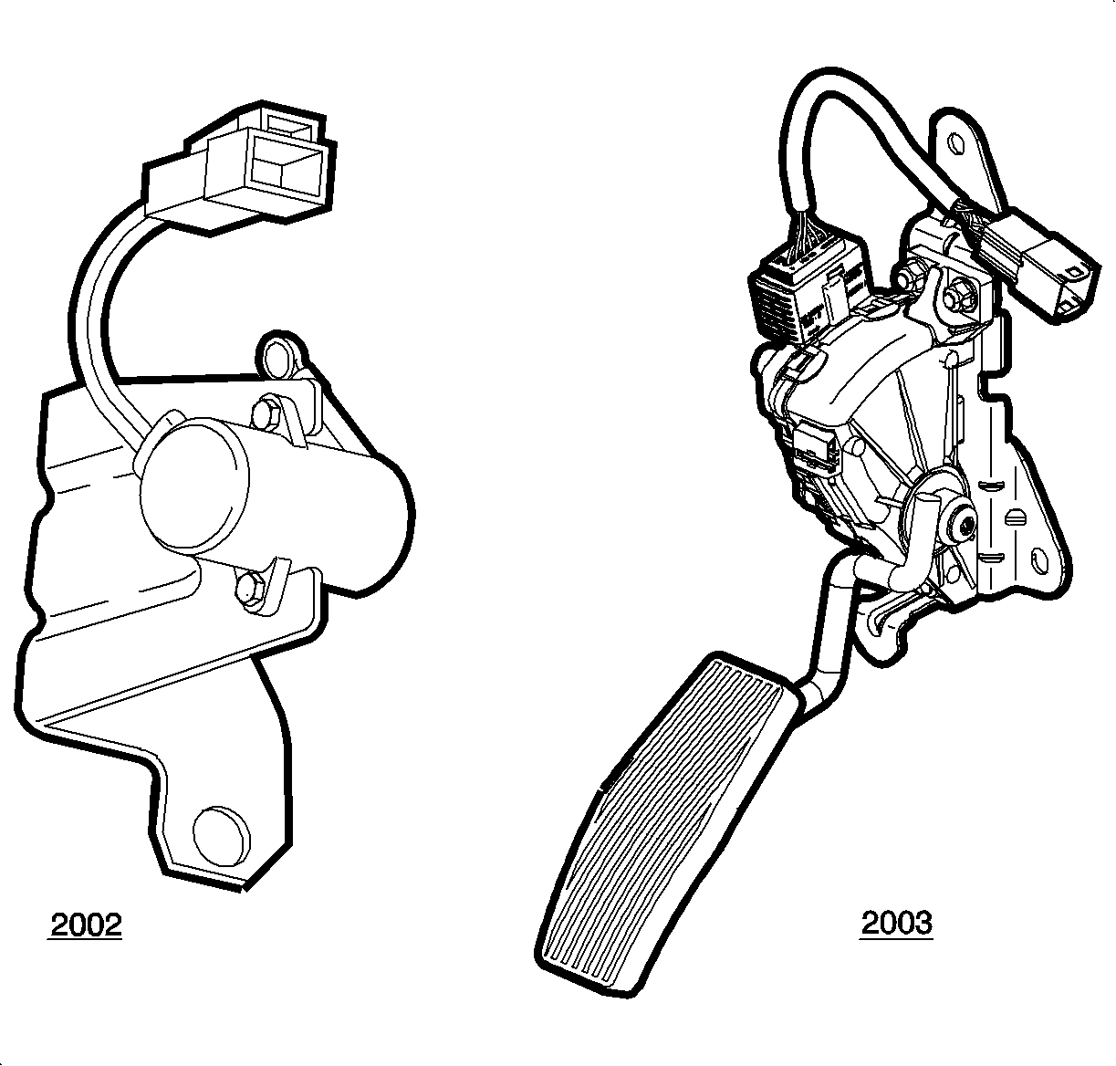
The accelerator pedal position (APP) sensors 1 and 2 are located on the accelerator pedal assembly. The L81 engine does not use a traditional throttle cable between the accelerator pedal and throttle body. Instead, these 2 sensors are used to relay accelerator pedal angle input to the engine control module (ECM). These 2 sensors are 2 potentiometers that vary resistance depending on pedal movement. As the accelerator pedal moves from rest to the full travel position, the APP sensor 1 signal voltage increases from 0.25-3.97 volts (2002), 0.88-3.78 volts (2003), while the APP sensor 2 signal voltage increases from 0.22-1.92 volts (2002), 0.49-1.84 volts (2003). APP sensor 2 signal voltage is always ½ the value of APP sensor 1 throughout the entire pedal range.
The ECM continuously monitors each APP sensor circuit for low and high voltage faults as well as performing a comparison check between each signal. If an error in 1 of the sensor signals were detected, the ECM would default to 1 of the 2 limp-home modes, limited pedal range, about 10 percent, with slow acceleration. The vehicle would still be able to travel at highway speeds, as the ECM would now use the opposite sensor for the driver's pedal input.
A/C Pressure Sensor
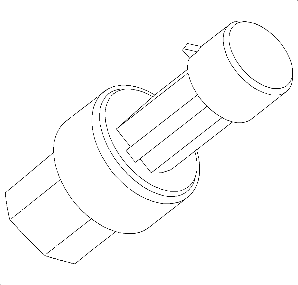
The air conditioning (A/C) pressure sensor is located in the A/C high side pressure refrigerant line in front of the air box. The pressure sensor is a transducer that varies resistance according to the absolute pressure inside the high side refrigerant line. The sensor is used by the engine control module (ECM) to determine appropriate cooling fan speed, low, medium, or high, during A/C operation. The sensor is also used by the ECM to turn OFF the A/C relay if the refrigerant pressure is not within 180-2898 kPa (26-420 psi gage pressure). The normal maximum range of the sensor can vary from 0.2 volts at 0 psi gage to 4.9 volts at 453 psi gage.
Camshaft Position (CMP) Sensor
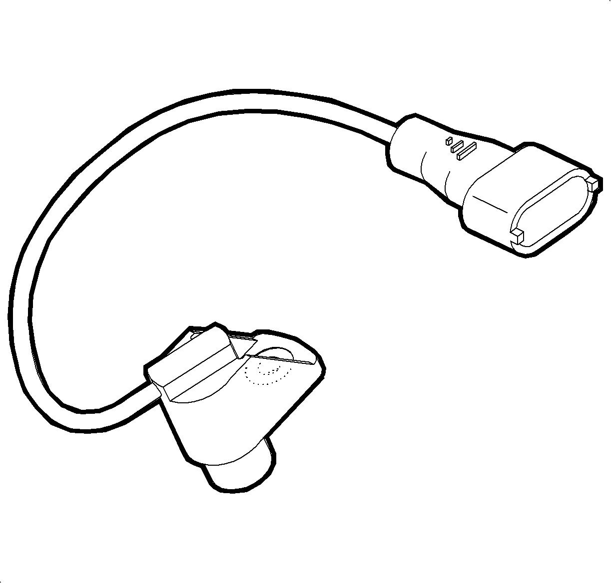
The camshaft position (CMP) sensor is located to the left of the cylinder 2, 4, 6 timing belt cover/exhaust camshaft sprocket. The CMP sensor is a hall effect switching device used to determine the position of the bank 2 exhaust camshaft. The CMP sensor detects a single tooth on the reluctor wheel of the camshaft, which denotes the 90 degrees before top dead center (TDC) cylinder #1 compression stroke. The sensor is used by the engine control module (ECM) to determine when cylinder # 1 is approaching top dead center necessary to synchronize the correct firing order. The CMP sensor is also used to enable sequential or independent fuel injection necessary for lowering tailpipe emissions, improving driveability, and to enable spark knock control.
As the reluctor wheel tooth rotates past the sensor, the sensors internal hall effect device pulls the signal circuit to ground. Therefore, the ECM expects to one see one high (5 volts) to low (0 volts) voltage transition once every 2 crankshaft rotations as the reluctor tooth passes the sensor. The signal circuit should be at 5 volts at all times except when the transition occurs. If an error occurs in the CMP sensor circuit, the ECM will take NO default actions. However, it will attempt to make a good guess on which mating cylinder to provide spark and fuel to, based on where the engine had stopped on the last ignition cycle. Therefore, if the ECM chooses incorrectly, the engine may or may not start on the next ignition cycle. If the CMP sensor signal is lost during the ignition cycle, the ECM will still provide the correct spark and fuel in the appropriate firing order.
Crankshaft Position (CKP) Sensor

The crankshaft position sensor (CKP) is located underneath and slightly to the left of the oil filter housing. The CKP sensor produces an AC voltage of different amplitude and frequency depending on the velocity of the crankshaft reluctor wheel. The crankshaft reluctor wheel contains 58 teeth that are 6 degrees apart with a 12 degree span that is uncut. This 12 degree span is used to locate the cylinder #1 top dead center (TDC) piston position used for engine synchronization. The CKP sensor in conjunction with the camshaft position (CMP) sensor can properly synchronize spark timing, fuel timing, and spark knock control.
The large numbers of teeth on the reluctor wheel are used to correctly detect engine misfires. The ECM automatically learns the variation between all of the 58 teeth under 24 different engine speed/load ranges. To correct detect misfires, the ECM will monitor the time it takes to pass 20 of the teeth, 120 degrees of crankshaft rotation, after a cylinder has fired. If the time, based on engine speed and load, to pass the 20 teeth is too long, a cylinder misfire has occurred.
Electronic Ignition (EI) Module With Coil Assembly
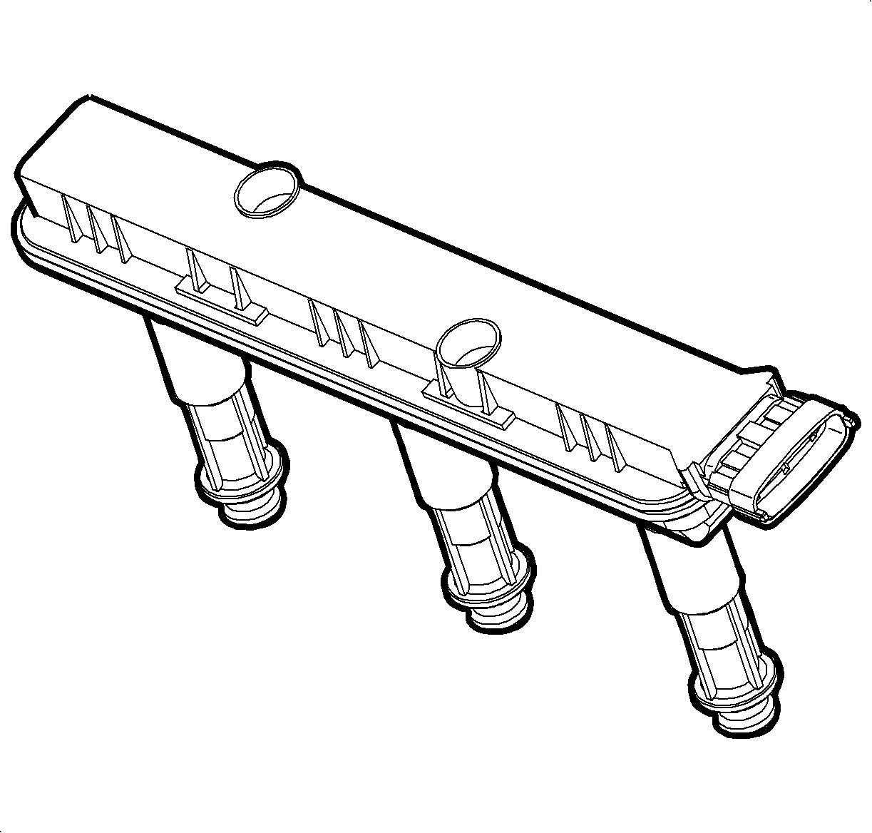
Each electronic ignition (EI) module, there are 2 total, is located directly over each cam cover. The electronic ignition system uses a coil over plug design used to eliminate the need for spark plug wires. Each EI module houses 3 primary coils, 3 secondary coils, as well as 3 drivers used to supply current to each of the 3 primary coils. Each secondary coil fires independently of 1 another solely based on engine control module (ECM) control. The ECM sends a low current 5 volt control signal, which turns ON a driver internal to the EI module allowing current to flow to 1 of the 3 primary coils. The time the ECM holds the control signal high is called the dwell time. As the ECM turns OFF the control signal, the secondary coil will fire out of its secondary tower. The spark will travel down the spark plug boot across the spark plug gap to ignite the cylinder air/fuel charge. The ECM uses 3 independent control signals to fire each cylinder within that specific bank.
Engine Control Module
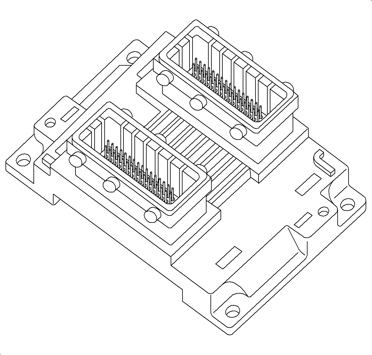
The engine control module (ECM) is a hybrid design microprocessor based computer that is the main component of the engine control system. The ECM uses various sensors to optimize fuel/spark/air delivery in order to achieve optimum engine operation. This is done by receiving inputs from engine sensors, processing information, and commanding outputs to output devices.
The ECM performs advanced diagnostic tests on different sensors and systems to assure the vehicle is operating properly. Routine checks are run throughout a drive cycle on sensor circuits. The ECM monitors hard circuit failures as well as signals that are out of range during specific driving conditions. When a fault is detected, the ECM will store Freeze Frame/Failure Records data and set a diagnostic trouble code (DTC).
Engine Coolant Temperature (ECT) Sensor
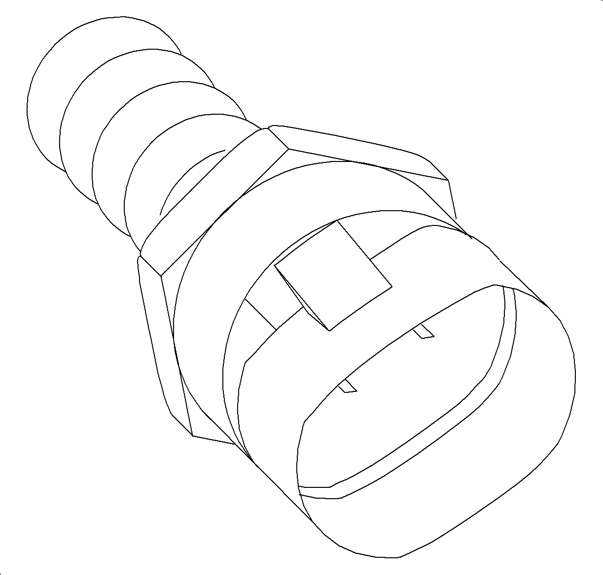
The engine coolant temperature (ECT) sensor is located in the coolant bridge directly underneath the rear intake manifold runner diaphragm, the side of the engine opposite the timing belt cover. The ECT sensor is used by the ECM for the base fuel control calculation, cooling fans operation, EVAP purge solenoid control, EGR operation, ignition timing, oil life monitoring, idle speed control, as well as many diagnostic trouble code enable functions. There is ONLY 1 engine coolant temperature sensor on this engine used to control the cooling fans, coolant temperature gage, and coolant temperature telltale.
Important: The ECM uses only ONE pull-up resistor throughout the entire ECT sensor range.
The ECT sensor is a thermistor that changes resistance according to changes in engine coolant temperature. When the engine coolant temperature is low, the ECT sensor resistance is high, with high signal voltage at the ECM. As the temperature of the coolant increases, the sensor resistance decreases, with lower signal voltage at the ECM. The ECM supplies the sensor 5 volts through a pull-up resistor to the sensor, which is connected to ground. The ECM uses the voltage value on the signal line to determine engine coolant temperature.
C | F | OHMS |
|---|---|---|
Temperature vs Resistance Values (Approximate) | ||
100 | 212 | 177 |
90 | 194 | 241 |
80 | 176 | 332 |
70 | 158 | 467 |
60 | 140 | 667 |
50 | 122 | 973 |
45 | 113 | 1188 |
40 | 104 | 1459 |
35 | 95 | 1802 |
30 | 86 | 2238 |
25 | 77 | 2796 |
20 | 68 | 3520 |
15 | 59 | 4450 |
10 | 50 | 5670 |
5 | 41 | 7280 |
0 | 32 | 9420 |
-5 | 23 | 12,300 |
-10 | 14 | 16,180 |
-15 | 5 | 21,450 |
-20 | -4 | 28,680 |
-30 | -22 | 52,700 |
-40 | -40 | 100,700 |
The ECM may ground fan control 1 and/or fan control 2 based on the reading from the ECT sensor. Under normal operating conditions, both cooling fans operate on low speed whenever the ECT is greater than 96°C (205°F), on medium speed if the ECT is greater than 99°C (210°F), and on high speed if the ECT is greater than 102°C (216°F). The cooling fans will turn OFF when the temperature drops below 92°C (198°F). If the engine is turned OFF and the ECT is above 105°C (221°F), the cooling fans will run on low speed for 7 minutes regardless of how fast the ECT cools down. If the engine is turned OFF and the ECT is above 110°C (230°F), the cooling fans will run on low speed for 8.5 minutes regardless of how fast the ECT cools down. If a low/high ECT sensor circuit fault, DTC P0117 or P0118 is set, with the engine running, the ECM will command the cooling fan control module to run the fans on high speed to protect the engine and transaxle until the condition is corrected.
Important: The scan tool displays AC HIGH SIDE PRESSURE in absolute pressure. To convert to gage pressure, subtract 101 kPa or (14.7 psi).
The ECM can control the cooling fan speeds based on the A/C pressure sensor. The ECM will turn both cooling fans on low if the A/C high side pressure is greater than 1199 kPa (174 psi gage pressure), then turn them both OFF once the pressure drops below 799 kPa (116 psi gage). The ECM will turn both fans on medium if the A/C high side pressure is greater than 1599 kPa (232 psi gage), then turn them both to low once the pressure drops below 1299 kPa (188 psi gage). The ECM will turn both fans on high if the A/C high side pressure is greater than 2199 kPa (319 psi gage), then turn them both to medium once the pressure drops below 1799 kPa (261 psi gage).
COOLANT TEMP GAGE: The ECM controls the coolant temperature gage by sending gage position messages to the BCM over the CAN link based on ECT sensor readings. The BCM averages the temperature over time allowing the gage to move slowly and remain in a relatively stable position as temperature varies. The BCM then sends the averaged information to the I/P cluster over the class II link to position the gage.COOLANT TEMPERATURE TELLTALE: The coolant temperature telltale is used to alert the driver that the engine may be in an overheated condition. The ECM controls the coolant temperature telltale by sending a message to the BCM over the controller area network (CAN) link, who will send a message to the I/P cluster over the class II link to turn ON the telltale. The ECM will send the message when the ECT sensor reading is above 118°C (244°F). If this condition exists, the ECM will set DTC P0117. If a high temp/low voltage fault exists in the ECT sensor circuit, the signal is considered invalid and the coolant temperature telltale will NOT be illuminated. The cooling fans will be commanded ON high.
Engine Oil Pressure (EOP) Switch
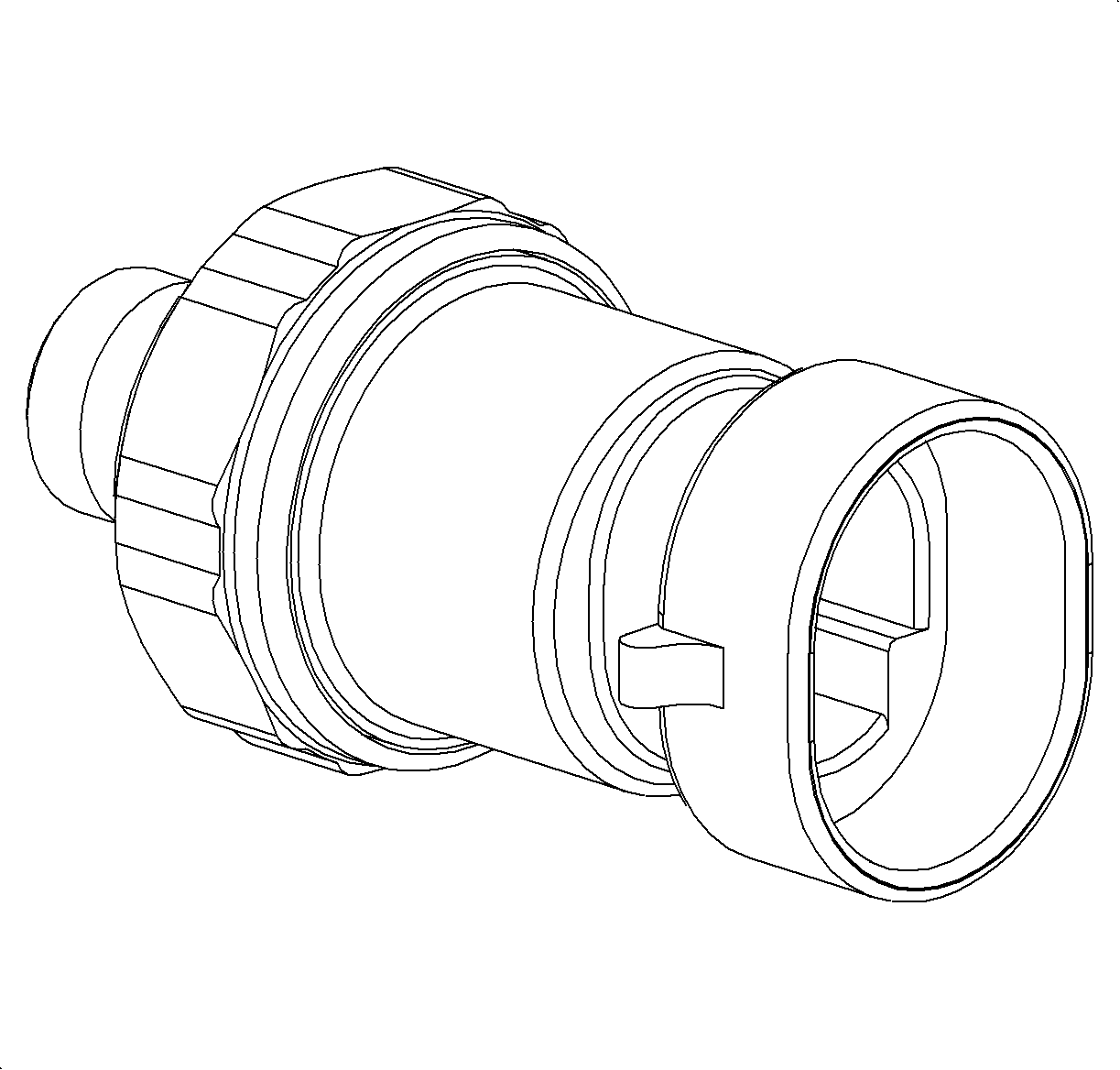
The engine oil pressure (EOP) switch is located towards the lower portion of the engine block (cylinder #1) underneath the generator. The EOP switch is a normally closed switch that opens when engine oil pressure exceeds 1.4-5.8 psi. The ECM supplies ignition voltage through a resistor to the EOP switch. With the ignition ON and the engine OFF, the ECM EOP switch input will be low, near 0 volts, switch closed. When the engine is started, end engine oil pressure exceeds 1.4-5.8 psi, the switch opens and the ECM EOP switch input goes high , ignition voltage.
EVAP Purge Solenoid
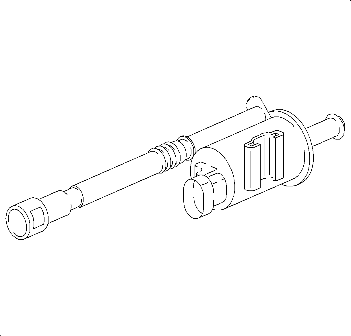
Important: During normal purge mode, the ECM will not update the long term fuel trim values. When purge mode is enabled, the ECM will use the previous stored long term fuel trim values. The ECM will periodically cycle the purge mode ON and OFF to update the long term fuel trim.
The EVAP purge solenoid is located towards the rear of the air box. When the EVAP purge solenoid is commanded ON, fuel vapors are drawn in to the engine via manifold vacuum supplied to the solenoid. As the solenoid is commanded ON, fresh air flows around the normally open EVAP vent solenoid, through the EVAP canister. Vapors that are stored in the charcoal are drawn up through the EVAP purge solenoid to be consumed in the normal combustion process. The normally closed EVAP purge solenoid is commanded a certain duty cycle by the ECM in order to precisely control the vapor flow. The EVAP purge solenoid will also open and close during the EVAP Diagnostic System Test performed by the ECM necessary to perform EVAP leak diagnostics.
EVAP Vent Solenoid
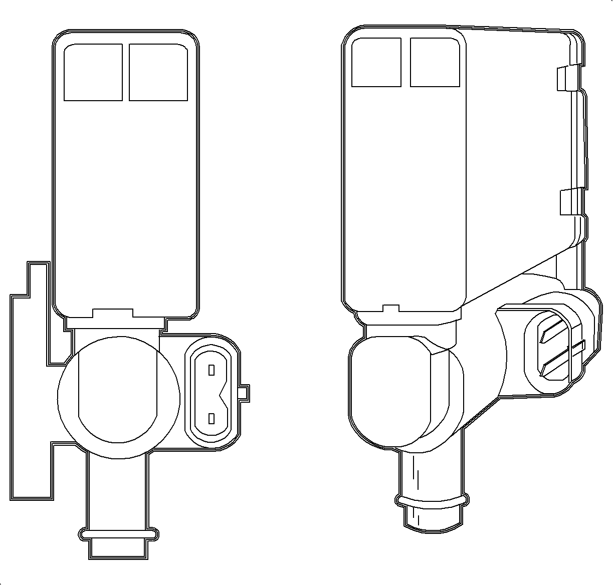
The EVAP vent solenoid is located in the EVAP vent box located on the top of the fuel filler neck. The EVAP vent solenoid is used solely for EVAP leak diagnostics. The solenoid is a normally open valve when commanded OFF and closes when commanded ON. The EVAP vent solenoid is closed during parts of the EVAP diagnostic system test performed by the ECM to enable a vacuum to be pulled on the EVAP system used to detect EVAP system leaks.
EVAP Service Port
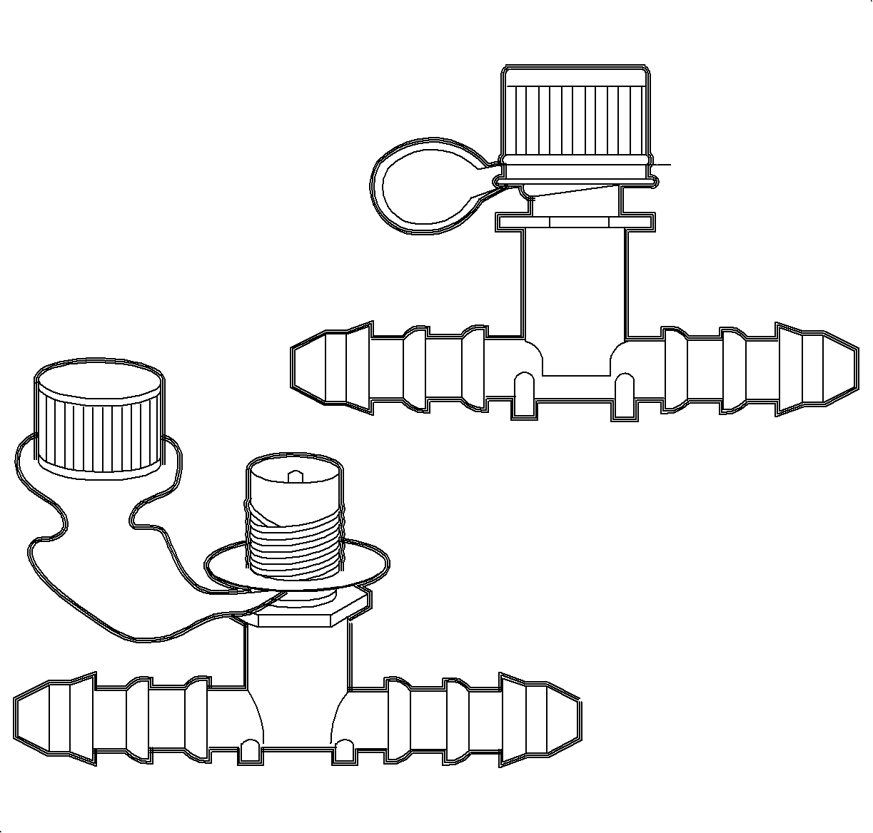
The EVAP service port is located in the EVAP purge line under the hood near the EVAP purge solenoid. The service port is identified by a green colored cap. The port is underhood near the EVAP purge solenoid in the EVAP line. The port contains a shrader valve to allow the connection of the service tool kit, J41413-A Evaporative Emissions System Tester .
Exhaust Gas Recirculation (EGR) Valve
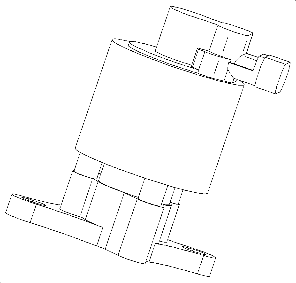
The EGR system is used to decrease emission levels of oxides of nitrogen (NOx) which can have harmful environmental effects if released into the atmosphere in large quantities. NOx forms during combustion in amounts dependent on the concentration of oxygen in the combustion chamber and the temperature of the combustion process. By diluting the incoming fuel/air charge with exhaust gases, the peak combustion temperature is reduced due to the lower concentration of oxygen, and NOx emissions are also reduced.
The ECM has to determine an appropriate amount of exhaust gas to introduce into the combustion chamber. Too little EGR can yield high NOx, while too much can disrupt combustion events. The ECM considers ECT, TP, MAP, IAT, RPM, and vehicle speed to determine an appropriate amount of EGR.
The EGR valve contains a position feedback circuit acting as a potentiometer which varies a signal voltage in the range of 0.5-4.5 volts. This allows for precise control of the actual position of the EGR pintle.
The solenoid is energized by current that creates an electromagnetic field. This field causes the armature assembly to pull upward, lifting the pintle a variable amount off the base. The exhaust gas then flows from the exhaust manifold port to the intake manifold. The position of the pintle is read by the pintle position sensor, and the ECM makes adjustments to the current to match the actual pintle position to a desired pintle position.
Too much EGR flow at idle, cruise, or cold operation can cause the following conditions:
| • | The engine stops after a cold start. |
| • | The engine stops at idle after deceleration. |
| • | The vehicle surges during cruise. |
| • | The vehicle has a rough idle. |
Too little EGR flow allows combustion temperatures to get too high during acceleration and load conditions. This could cause:
| • | Spark knock or detonation |
| • | Engine overheating |
Fuel Injectors
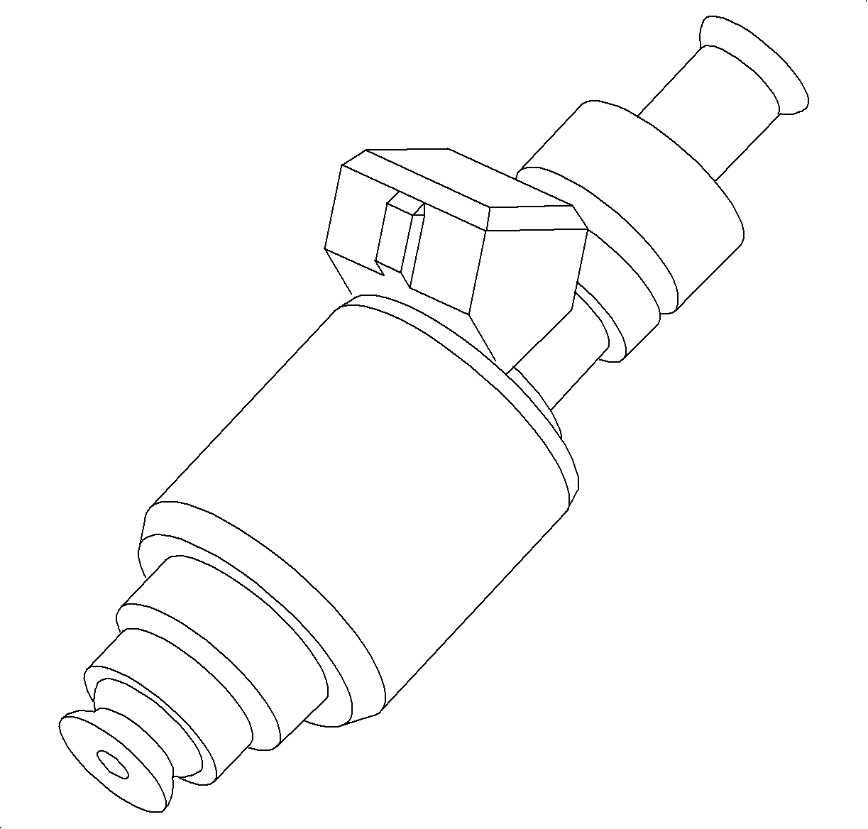
The fuel injection system on the 3.0L engine utilizes sequential fuel injection in which the ECM independently controls each fuel injector. The ECM grounds each fuel injector circuit for a certain length of time based on engine operating parameters. The fuel control system is designed to maintain a 14.7:1 air/fuel ratio under all engine running conditions except deceleration and cold engine startup. The ECM can turn fuel injectors OFF during deceleration, misfire diagnostics, traction control, and during 1 of the 2 throttle control system limp-home homes. The REDUCED POWER telltale will be illuminated.
Fuel Level Sensor
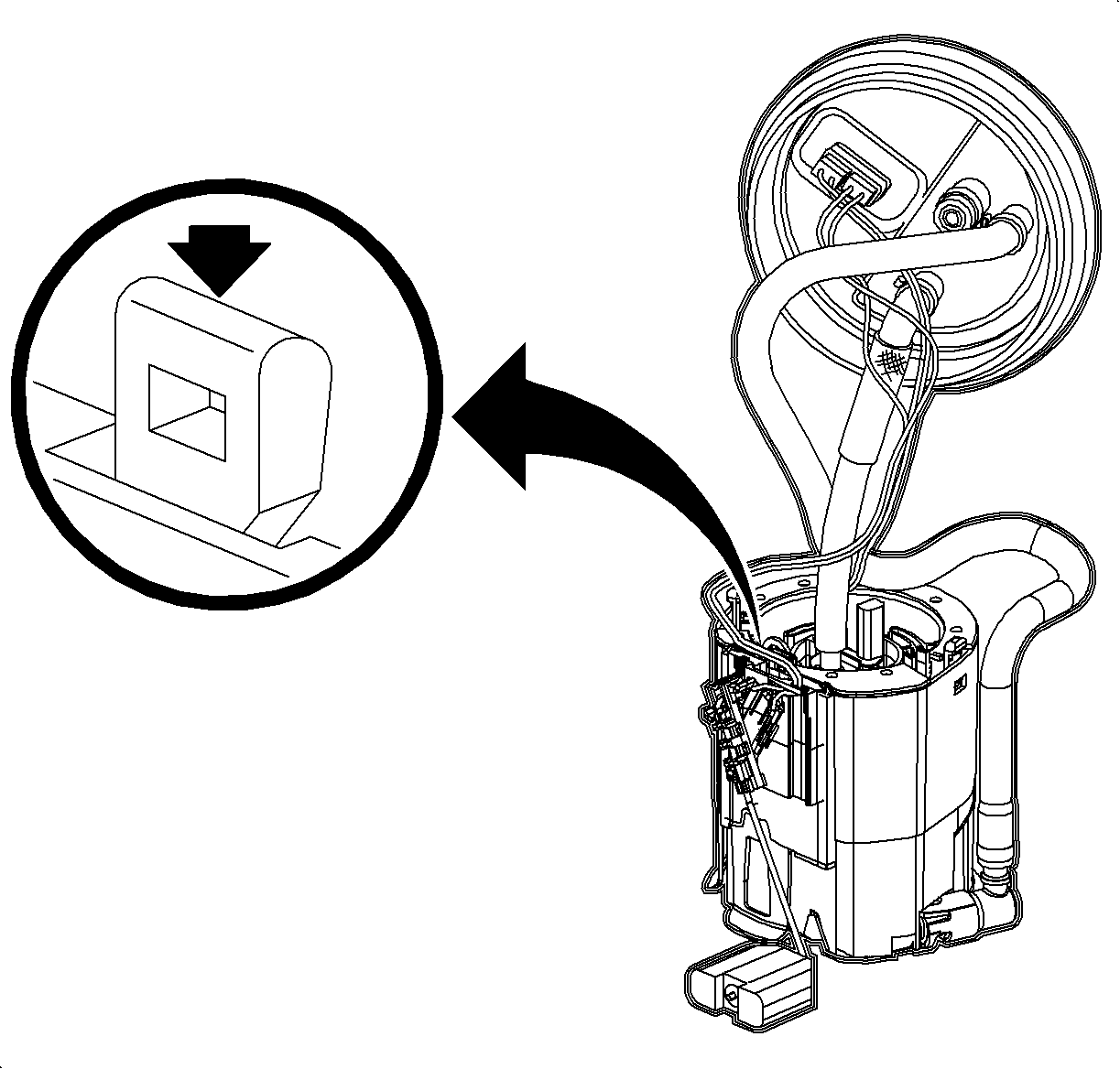
The fuel level sensor is part of the fuel tank sender assembly inside the fuel tank. This sensor varies resistance according to changes in the level of fuel in the fuel tank. The ECM supplies a 5-volt reference to the sensor, which is connected to ground. When the level in the fuel tank is low, the sensor resistance is high, with high voltage on the signal line. As the fuel level increases, the sensor resistance decreases, and voltage decreases on the signal line. The ECM uses the signal voltage to determine fuel tank level. The fuel level sensor is also used to determine fuel level necessary for EVAP diagnostics.
FUEL GAGE: The ECM averages the fuel tank level reading from the fuel level sensor over time and will also average the value if a circuit fault were to occur. The ECM sends this averaged information to the BCM over the controller area network (CAN) link. The BCM averages the information for fuel tank sloshing (vehicle speed) and sends this averaged fuel level to the I/P cluster over the class II link. The I/P cluster then positions the gage.LOW FUEL TELLTALE: If the fuel level is low, the ECM will send a message to the BCM over the CAN link, who sends a message to the I/P cluster over the class II link to turn ON the Low Fuel telltale. The Low Fuel telltale will illuminate when approximately 7.9 liters (2.1 gallons) maximum range is 4.9-11.4 liters (1.3-3 gallons) of usable fuel remains in the tank.
Fuel Pump
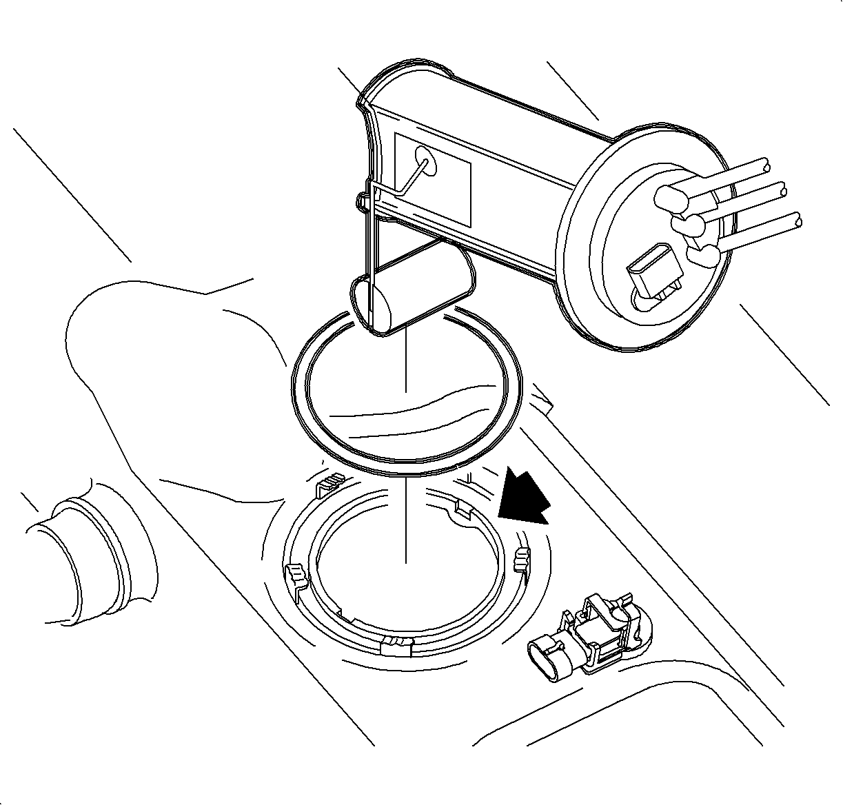
The fuel pump motor, located inside the fuel tank, supplies fuel pressure to the fuel injectors. The engine control module (ECM) controls the fuel pump motor by controlling the fuel pump relay in the underhood fuse block (UHFB). The fuel pump motor is supplied constant ignition voltage whenever the fuel pump relay is turned ON. The ECM turns ON the fuel pump relay whenever the engine is running or cranking. The ECM will NOT run the fuel pump unless crankshaft position sensor pulses are being received.
Fuel Tank Pressure (FTP) Sensor
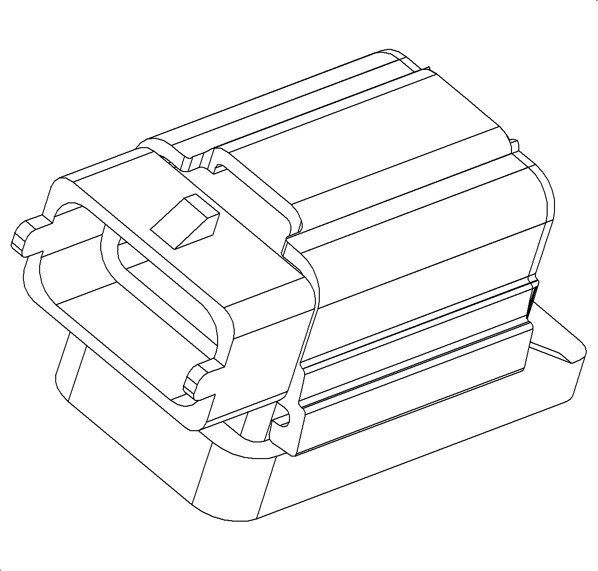
The fuel tank pressure (FTP) sensor is located on top of the fuel sender assembly, located on top of the fuel tank. The FTP sensor is used solely for EVAP leak diagnostics, but also aids in disabling purge mode if too much vacuum is present in the fuel tank during normal purge operation, if the vent system is blocked. This will prevent the fuel tank from possible damage.
The FTP sensor is a transducer that changes resistance based on the difference between the fuel vapor pressure inside the fuel tank and the outside air pressure. The ECM supplies the sensor direct 5 volts and a reference return circuit. Normal signal voltage readings with the fuel cap removed should be between 2.35-2.85 volts, which represents atmospheric pressure. As pressure in the fuel tank increases above atmospheric, the signal voltage will increase above the atmospheric voltage reading. As the pressure in the fuel tank drops below atmospheric (vacuum), the signal voltage will fall below the atmospheric voltage reading. It is important to check the validity of the FTP sensor reading when diagnosing any EVAP system leak DTC, since the ECM uses the FTP sensor in all of its EVAP leak diagnostic measurements. A skewed sensor signal value may falsely set an EVAP leak DTC.
Generator
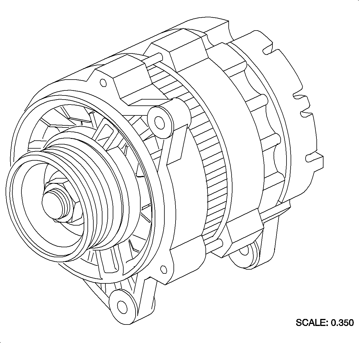
The ECM controls generator charging by supplying 12 volts on the generator L-terminal circuit whenever the ignition is turned ON or the engine is running. This control voltage is necessary for the generator to charge once the generator begins to spin. With the ignition ON and the engine OFF, the generator will ground the generator L-terminal circuit through a resistor. When the engine is started and the generator begins to charge, the generator will open the circuit, still using the 12 volt control voltage, signaling to the ECM that the generator is charging.
CHARGE TELLTALE: If the voltage at the ECM generator L-terminal is low when the engine is running, the ECM will send a message to the BCM over the controller area network (CAN) link, which will send a message to the I/P cluster over the class II link to turn ON the Charge telltale.Heated Oxygen Sensor (HO2S) Bank 1 Sensor 1 and Heated Oxygen Sensor (HO2S) Bank 2 Sensor 1
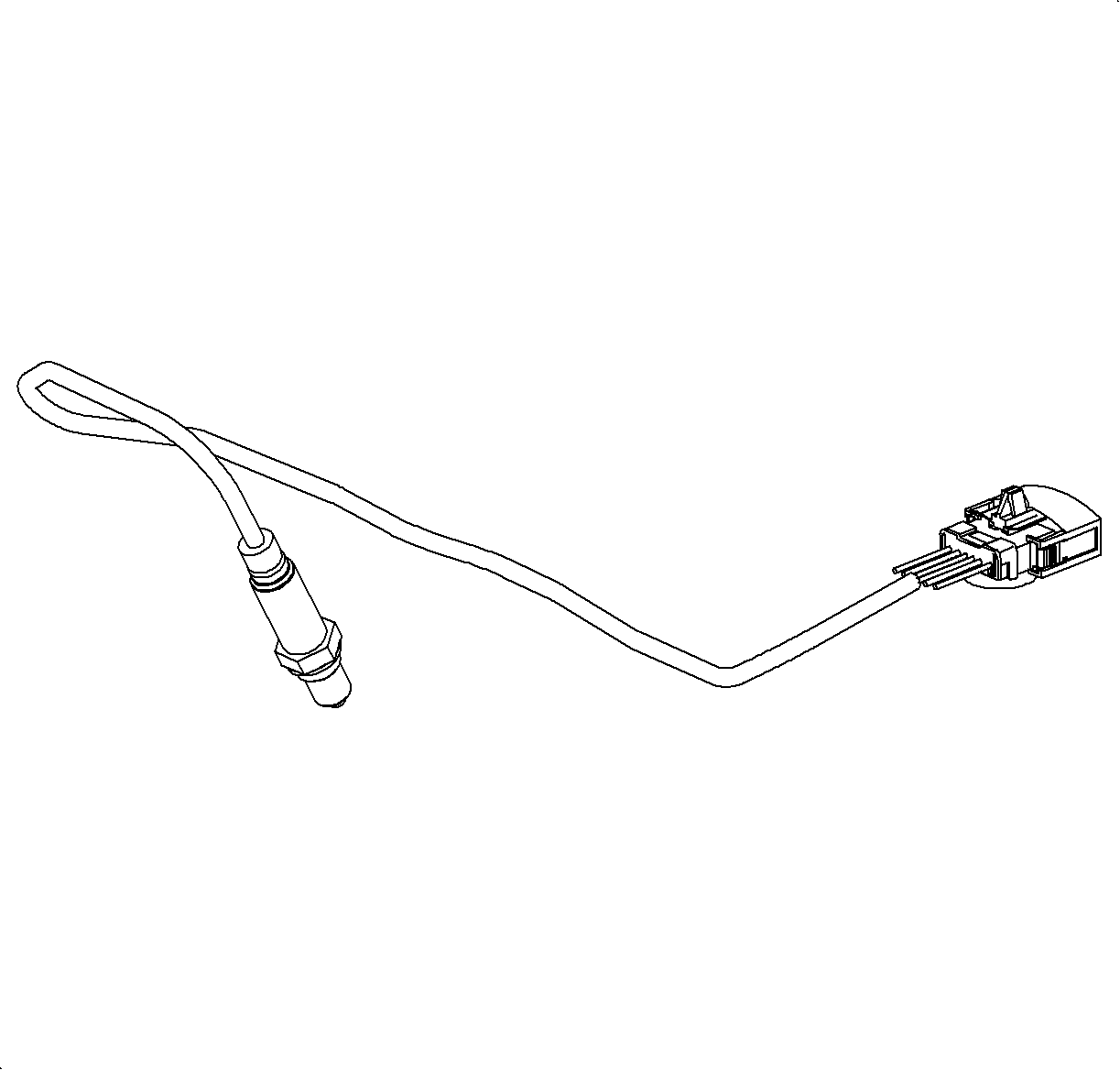
The heated oxygen sensor bank 1 sensor 1, cylinders 1, 3, 5 which are closest to the front of the dash, or heated oxygen sensor bank 2 sensor 1, cylinders 2, 4, 6 which are closest to the radiator, are both located in each exhaust manifold bank. The L81 engine uses air/fuel ratio sensors called lambda sensors instead of the traditional voltage producing switching type sensors. The lambda sensors allow for a wider range of air/fuel control from around 8:1 to 18:1. Using these sensors, the engine control module (ECM) can maintain Closed Loop operation, using the oxygen sensor for fuel control, under all engine running conditions except cold engine start-up and extended decelerations.
The scan tool provides a lambda value parameter for each of the 2 sensors. Lambda is described as the actual air/fuel ratio of the sensor divided by 14.7. For example, a lambda of 1.00 indicates that the sensor is detected a 14.7:1 air/fuel ratio. The higher the lambda value above 1.00, the leaner the exhaust the sensor is detecting. The lower the lambda value below 1.00, the richer the exhaust the sensor is detecting. Refer to the Fuel Control System Description in this section for a better understanding of how the hardware of these sensors work.
Each of the 2 lambda sensors contains a heater element controlled by the ECM necessary to speed up Closed Loop start times. The ECM will pulse the heater anytime the engine is running. The heater allows the sensor to become active within a maximum of 20 seconds after engine start at any ambient temperature if the sensor is functioning correctly.
Heated Oxygen Sensor (H02S) Bank 1 Sensor 2 And Heated Oxygen Sensor (H02S) Bank 2 Sensor 2

The heated oxygen sensor bank 1 sensor 2, cylinders 1, 3, 5 which are closest to the front of the dash, or heated oxygen sensor bank 2 sensor 2, cylinders 2, 4, 6 which are closest to the radiator, are both located in each exhaust pipe downstream from each pre-catalytic converter. The functions of the sensor are to monitor the efficiency of each pre-converter and for fuel trim biasing. Fuel trim biasing is the time the engine control module (ECM) will hold a rich or lean fuel control command designed to maintain a target HO2S sensor 2 voltage of near 600 mV.
The HO2S sensor 2 is a 4-wire sensor, 2 are used for the heater and the other 2 are used for the oxygen sensor signal. The H02S sensor 2 is an electrical source that responds to oxygen content out of the pre-catalytic converter. When the sensor reaches approximately 316°C (600°F), it produces a voltage based on the difference in oxygen between the atmosphere and exhaust gas out of the pre-converter. The ECM sends a bias voltage (450 mV) on the signal line, which can be read on the scan tool when the sensor is cold. When the HO2S sensor 2 is cold, it produces no voltage and has extremely high internal resistance. However, when the sensor heats up, it produces voltage that overrides the bias voltage. Normal sensor readings at steady cruise with a properly functioning catalytic converter will be steady around 500-800 mV with a target of 600 mV.
Intake Air Temperature (IAT) Sensor
The intake air temperature (IAT) sensor contains a thermistor, a semi-conductor device that changes resistance based on temperature. The IAT sensor is in the air intake passage of the engine air induction system as a part of the mass air flow (MAF) assembly. The engine control module (ECM) monitors changes in voltage on the signal wire due to resistance variations as the intake air temperature changes.
When the intake air is cold, the sensor resistance will be high, and the signal voltage will be near 5 volts. When the intake air is warm, the sensor resistance will become low, and the signal voltage will read closer to 0 volts.
The scan tool displays the temperature of the incoming air, not the voltage on the signal circuit. This should be near ambient air temperature when the engine is cold. The temperature should rise as the underhood temperature increases. If the engine has not been run for several hours, the IAT and ECT should read close to the same value.
Intake Manifold Runner Control (IMRC) Solenoid
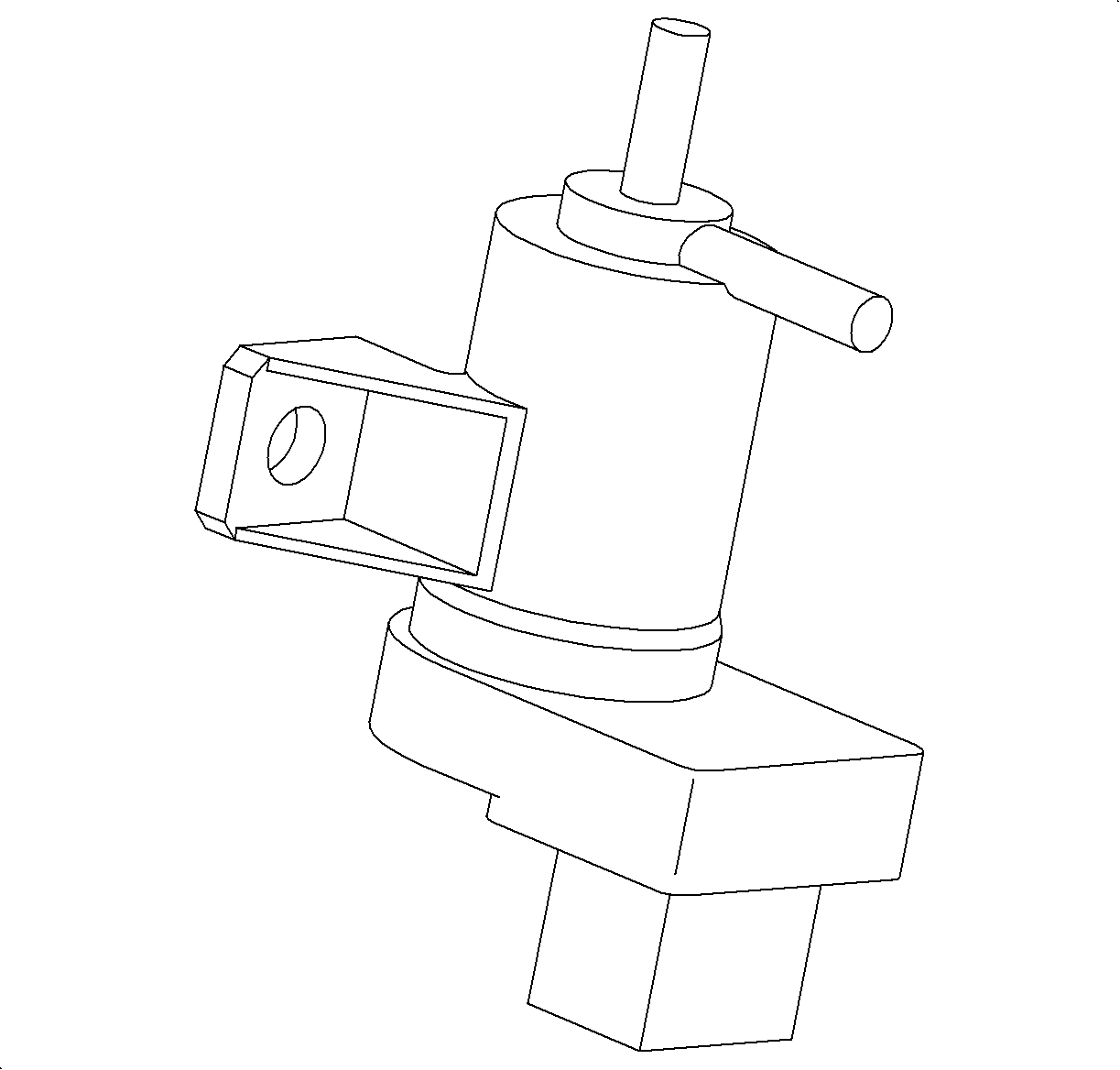
The intake manifold runner is a shaft with 1 flap located inside the intake manifold, which is controlled by an externally located vacuum operated diaphragm. As the diaphragm moves above a certain engine speed, 3,950 RPM/load range, the flap routes the intake air into the longer intake runners, which change induction airflow characteristics. The ECM controls the intake manifold runner diaphragm by controlling its vacuum supply via the intake manifold runner control (IMRC) solenoid. The IMRC solenoid is located on the left side of the vehicle fastened to the upper intake plenum. The IMRC solenoid is supplied continuos manifold vacuum, which is transferred to the intake manifold runner diaphragm whenever the solenoid is energized. The ECM controls the solenoid by supplying the circuit ground during higher engine speed/load ranges.
Knock Sensor
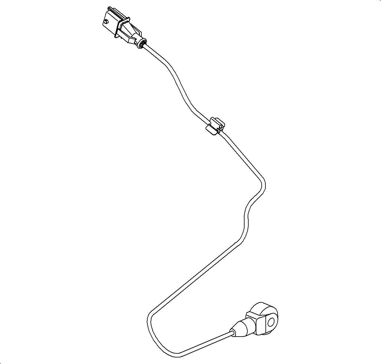
The knock sensors in the vehicle serve to detect abnormal vibration, spark knocking. There is a knock sensor on each of the 2 cylinder banks. Engine vibration causes the piezo-electric device within the knock sensor to produce an AC signal which is read by the ECM. The ECM will retard timing to a maximum correction based on the signal. The ECM is capable of detecting too much noise and too little noise. A noise level reading is taken at idle and used as a reference reading. There is a time frame around the TDC combustion event when the knock sensor signal is considered by the ECM.
Manifold Absolute Pressure (MAP) Sensor
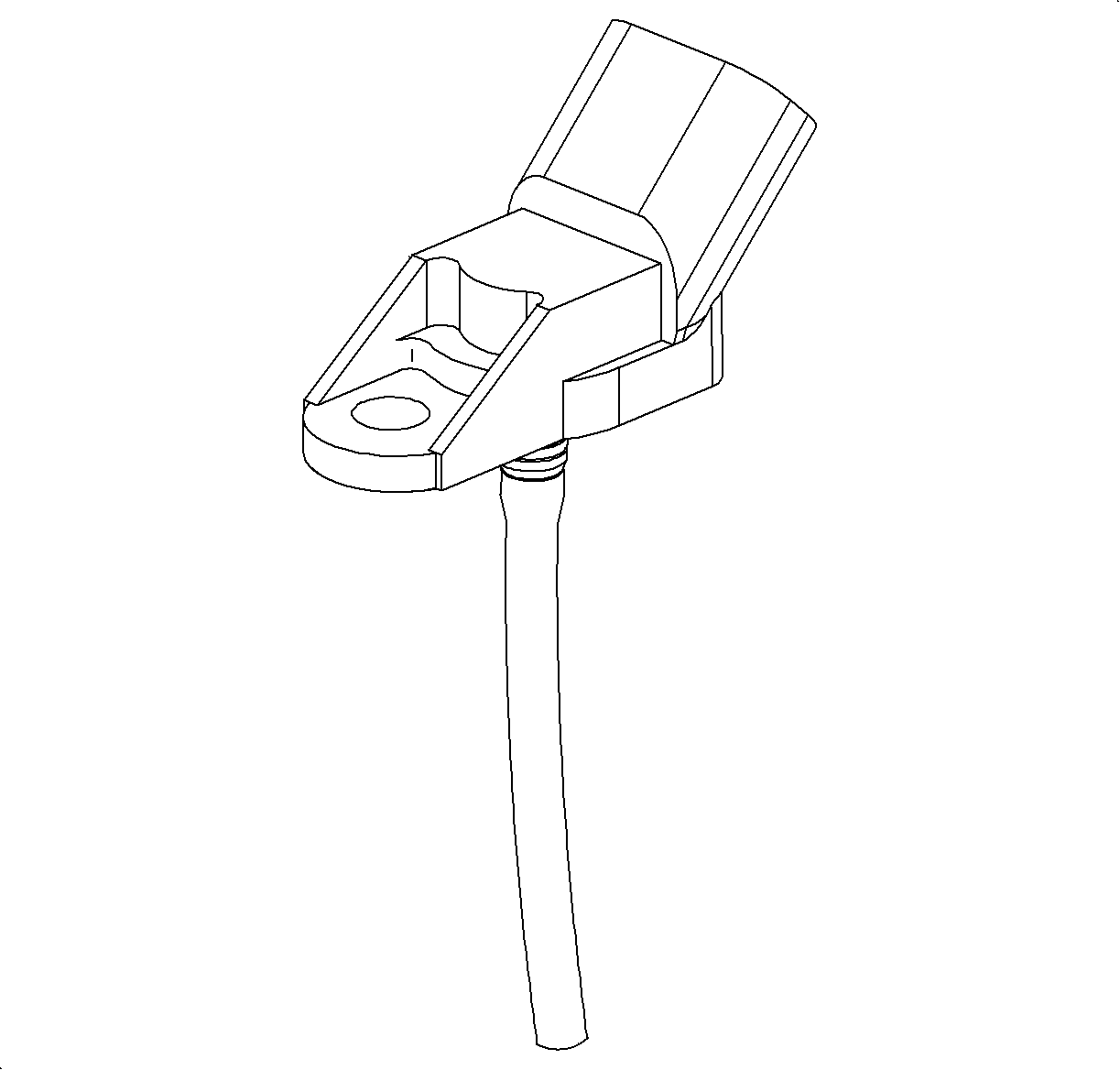
The MAP sensor voltage is converted by the ECM to an absolute pressure (kPa or psi). A high pressure, atmospheric pressure, produces an output of 4.5-5 volts, about 95-105 kPa (14-15 psi) absolute. A low pressure, engine vacuum, produces about 0.5-0.9 volts, about 37-50 kPa (5-7 psi) absolute. The MAP sensor is also used to calculate barometric pressure under certain conditions and for EGR flow diagnostics.
Mass Air Flow (MAF) Sensor
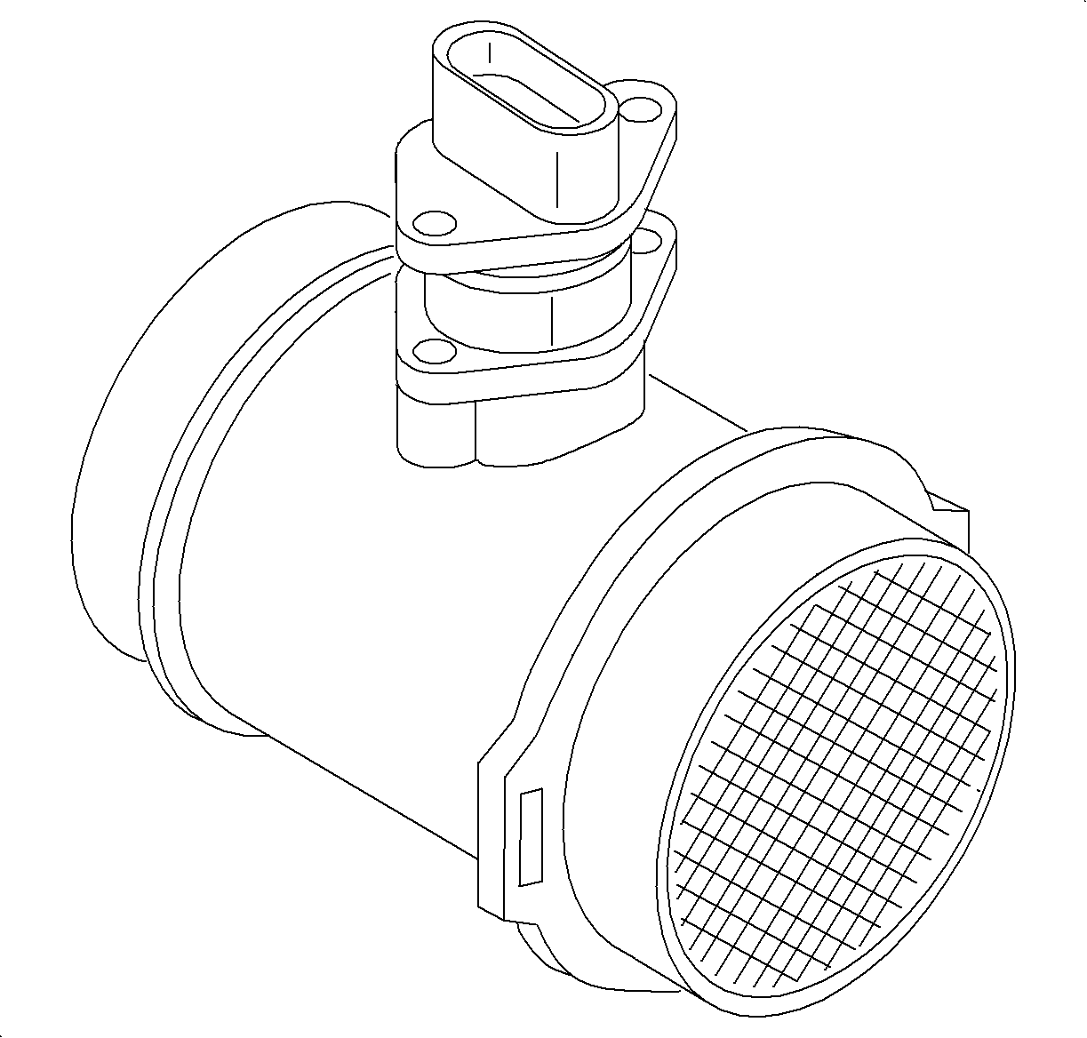
The mass air flow (MAF) sensor measures the amount of air that is ingested by the engine. The direct measurement of air entering the engine is more accurate than calculating the airflow from other sensor inputs. The sensor employs a hot film to measure the air flow rate. The MAF output voltage is a function of the power required to keep the sensing elements at a fixed temperature above ambient temperature as incoming air cools the sensing elements. As air flow increases, the current through the element increases.
Throttle Actuator Control (TAC) Module With Integral Throttle Position Sensors
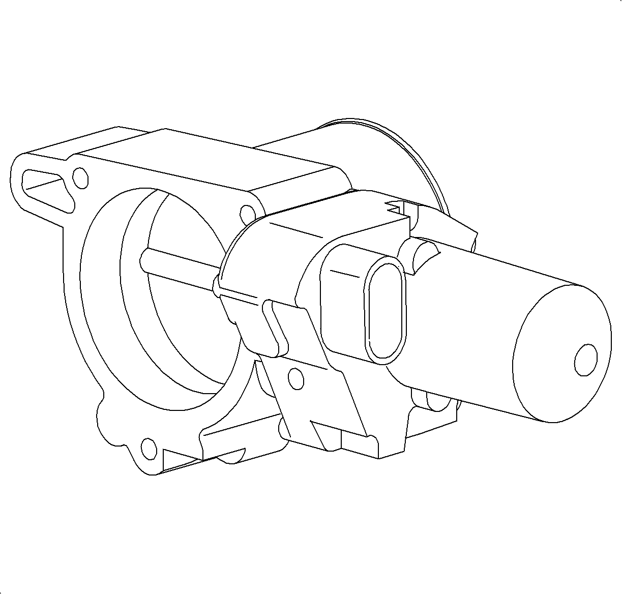
The L81 engine does not use a traditional throttle cable found on most other vehicles. The throttle actuator control (TAC) module, which is part of the throttle body assembly, contains a direct current actuator motor controlled by the ECM used to move the throttle plate, in either direction, and 2 throttle position (TP) sensors to determine throttle plate position. The throttle plate is held at a 7 percent rest position to a mechanical stop by a constant force return spring. This spring will hold the throttle plate to the stop when there is no current flowing to the actuator motor. There is another return spring, which creates constant force on the throttle plate only when the throttle plate is moved towards the full closed position.
Each time the ignition is turned ON, the ECM will perform a closed throttle test. During this test, it will close the throttle from the 7 percent rest position to the full closed position and allow it to return. This is performed to ensure the springs have enough force to close the throttle in case of an actuator motor failure.
Important: Anytime a throttle body or ECM is replaced, a relearn procedure MUST be performed. Refer to DTC P1526/P2176 for this procedure.
The ECM will also go through a throttle body relearn procedure 29 seconds after the ignition is turned ON with the engine OFF as long as certain conditions have been met. Refer to DTC P1526/P2176 for these conditions. During this learn procedure, the ECM will move the throttle from the rest to full closed position, then to around 14 percent. During this period, the TP sensors lower limits, the rest position of the TP sensors, the actuator motor force to overcome both spring pressures as well as the return rates of both springs are learned. If any of these parameters are out of range, a DTC will be set. The scan tool contains the parameter TAC LEARN COUNTER, which can be monitored during the learn procedure. The counter should start at 0 then count up to 9 or 11 counts during the 3 second relearn procedure. If the counter starts at 0 and goes to 9 or 11, the sensors, springs, and motor are OK. A relearn procedure is performed only once per ignition cycle.
Wheel Speed Signal Conditioner Module
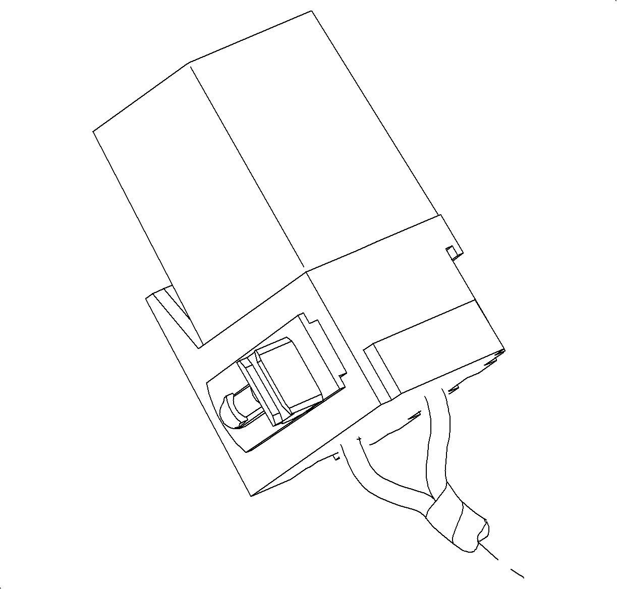
The wheel speed signal conditioner module for the L81 application is only equipped on vehicles without antilock brakes. The wheel speed signal conditioner module is located under the driver side I/P, which is orange in color and similar dimensionally to a relay. The module harness is tied to the I/P harness.
Important: The speedometer is ran off the output speed sensor signal, which is the direct input to the transmission control module (TCM). The TCM sends vehicle speed information over the controller area network (CAN) link to the body control module (BCM). The BCM in turn will send a message over the Class II link to the I/P cluster which will position the speedometer.
Vehicle speed on non-ABS vehicles is received from the right front wheel speed sensor. The wheel speed signal conditioner module is used to convert the A/C voltage of the sensor to a square wave. This is accomplished by pulse width modulating the vehicle speed output circuit to ground, which is pulled up to 12 volts through resistance in the ECM. The ECM interprets the square wave input as vehicle speed.
