Enhanced EVAP Emission System

EVAP System Operation
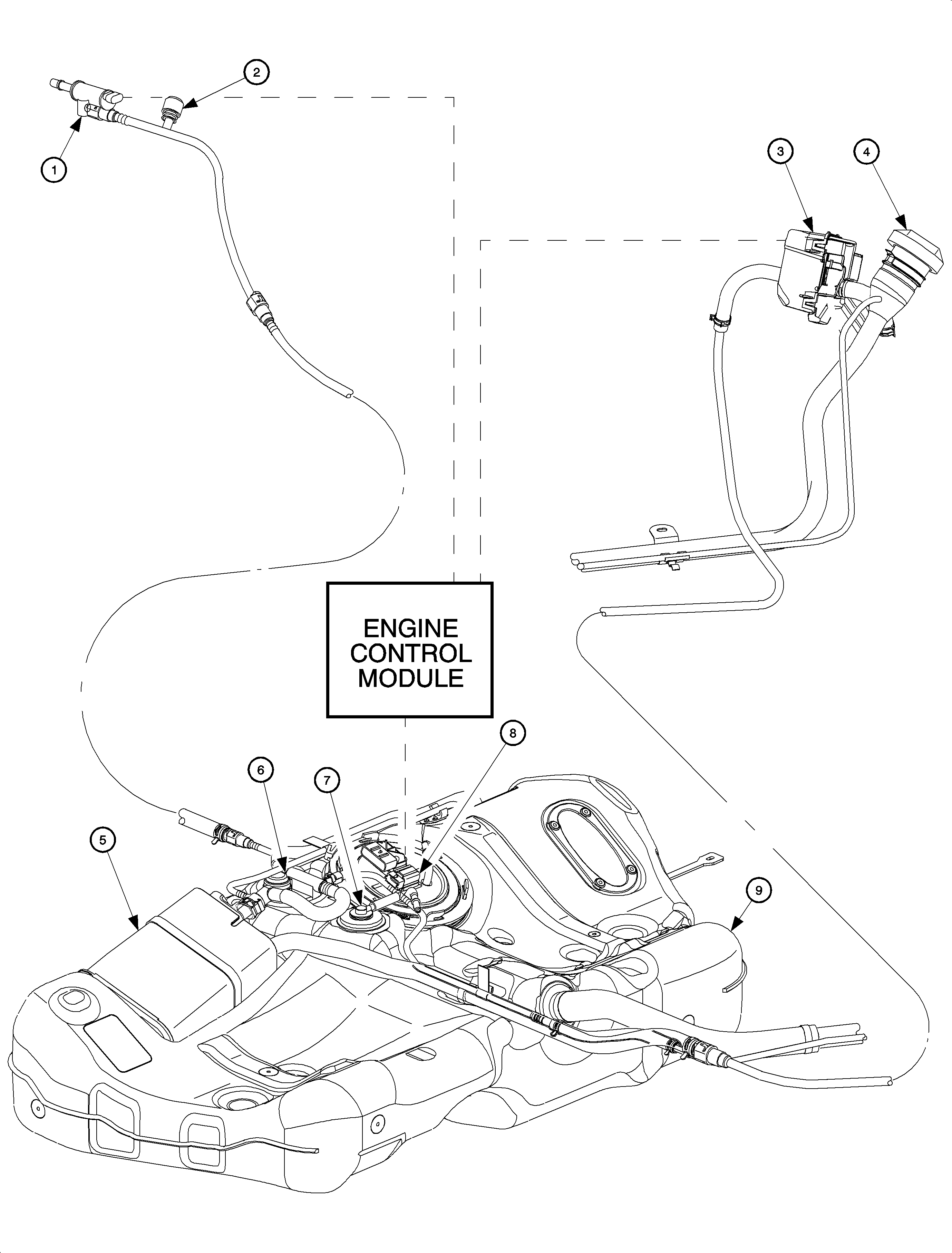
The enhanced EVAP system is used to limit unburned fuel vapors, or hydrocarbons,
from escaping into the atmosphere. Since fuel evaporation in the fuel tank is a normal
process, it is necessary to accumulate the unburned fuel vapors so they can be purged
into the intake manifold for combustion. The EVAP system consists of the following:
| • | EVAP purge solenoid -- located on the side of the air box |
| • | EVAP service port -- located underhood in the EVAP purge line near
the air induction box identified by a green colored cap |
| • | EVAP vent box which houses the EVAP vent solenoid -- located near
fuel filler neck |
| • | EVAP canister -- located on top of the fuel tank |
| • | Fuel level vent valve (FLVV) |
| • | Fuel tank pressure sensor -- located on top of the fuel tank |
| • | Engine control module (ECM) -- located directly on top of the intake
manifold |
When fuel from the fuel tank evaporates, the vapors flow though the fuel level
vent valve (FLVV), located on the top of the fuel tank, to the EVAP canister. The
EVAP canister is an active carbon fiber storage container that collects fuel vapors
and prevents them from entering the atmosphere. The EVAP canister is vented to the
atmosphere through the EVAP vent solenoid. The EVAP vent solenoid is a normally open
valve that only closes during parts of the EVAP diagnostic test.
When the ECM goes into purge mode, drawing fuel vapors into the intake manifold,
it will pulse width modulate the EVAP purge solenoid by grounding the EVAP purge solenoid
circuit. As the EVAP purge valve opens and closes, manifold vacuum draws fuel vapors
from the EVAP canister.
EVAP System Diagnostics
The ECM monitors the following EVAP system electrical components for open, low,
and high voltage faults:
| • | Fuel tank pressure sensor |
As part of the On-Board Diagnostics second-generation (OBD II) requirements,
the government mandates that all automobile manufactures detect a 0.51 mm (0.02 in)
or greater diameter leak in the EVAP system. To comply, the ECM monitors the EVAP
system for large and small leaks and whether the EVAP purge and vent solenoid valves
are stuck closed or open.
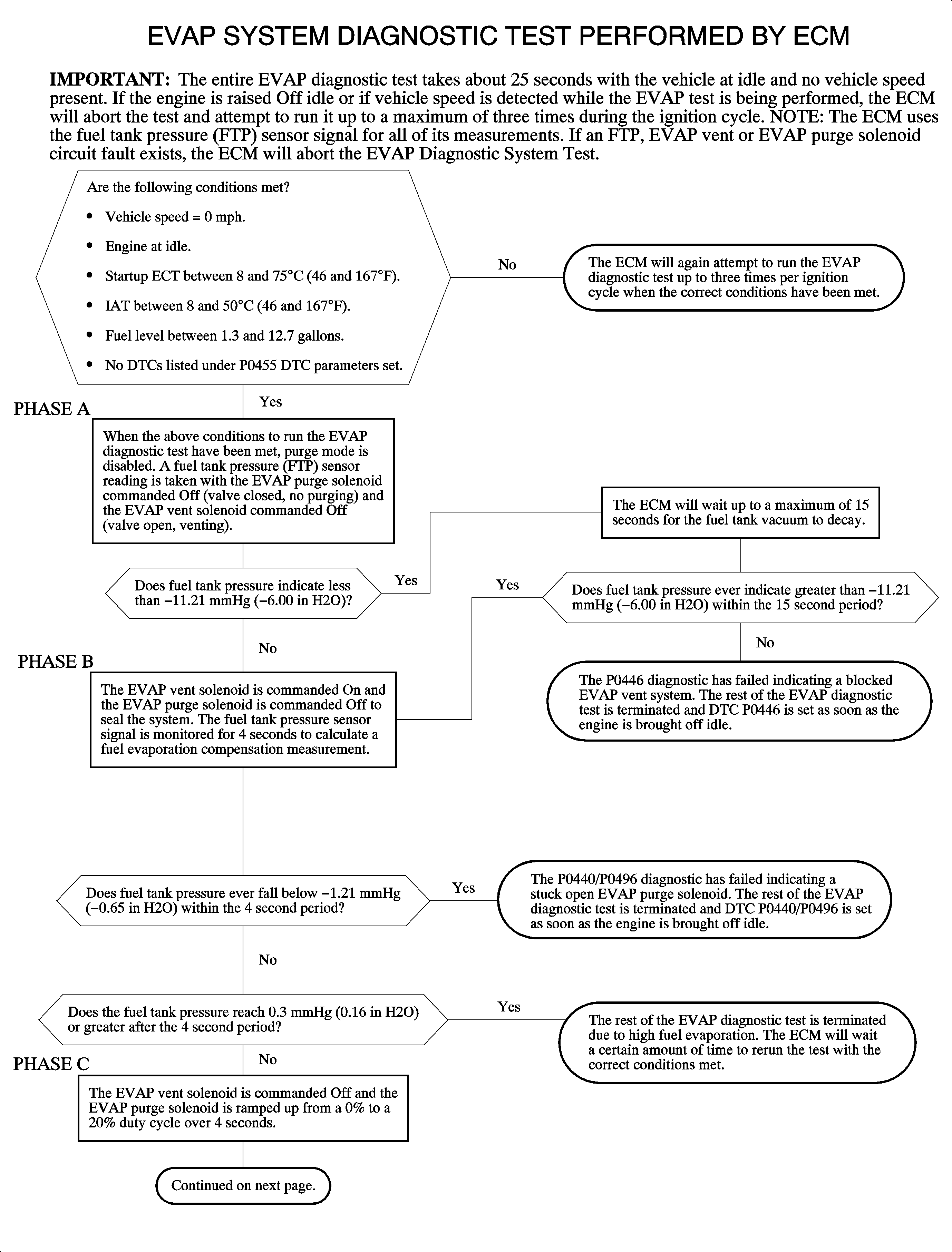
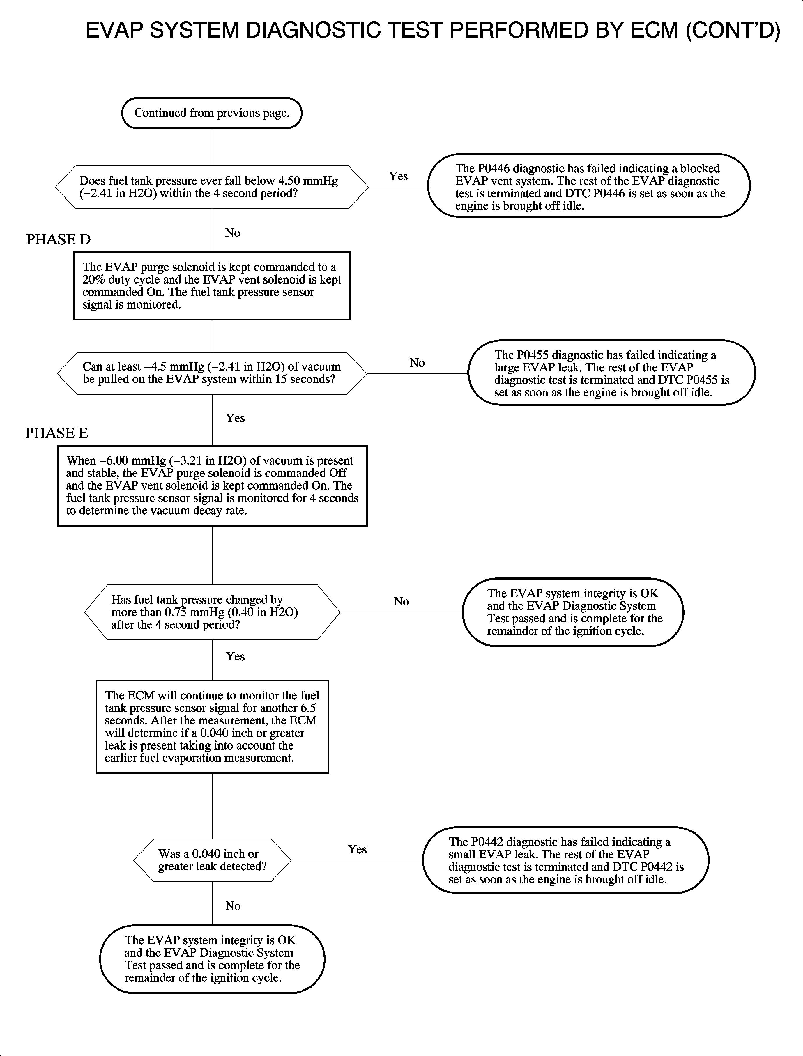
Important: The following flowchart consists of a series of tests run by the ECM, which
describes the entire EVAP DIAGNOSTIC TEST. Each step the ECM performs is dependent
on the accuracy of the fuel tank pressure sensor. The FUEL TANK PRESS. SENSOR reading
on the scan tool with the ignition ON and the engine OFF and the fuel cap removed
should read between 2.35-2.85 volts.


Diagnosing a Fault in the EVAP System
When the MIL is commanded ON and an EVAP DTC is set, there are certain ordered
steps that should be taken to ensure correct diagnosis.
Important: If any of the following DTCs are set, the ECM will NOT run the EVAP diagnostic
leak test.
- Diagnose any hard circuit fault fuel tank pressure (DTCs P0451, P0452
or P0453), EVAP purge solenoid (DTCs P0443, P0444 or P0445), or EVAP vent solenoid
(DTCs P0447, P0448 or P0449) DTCs first.
- Using the scan tool, monitor FUEL TANK PRESS. SENSOR with the ignition
ON and the engine OFF and the fuel cap removed. The voltage should be between 2.35-2.85
volts.
- Reinstall the fuel cap.
- If DTC P0440/P0496 or P0446 is set, diagnose that DTC next.
- If DTC P0455 or P0442 is set, diagnose that DTC next. A leak in
the system must be present if 1 of these 2 DTCs are set. Use the EVAP
System Leak Tester to locate the leak.
Evaporative Emissions System Tester Procedures
Important: The EVAP System Tester has the ability to serve 2 functions. It can induce
smoke in the EVAP system to determine where a small or large EVAP system leak exists,
and it can verify the integrity of the system after a fix has been performed by the
use of a flowmeter test. The flowmeter test introduces nitrogen into the system to
determine if a floating device is above a certain point. If the floating device is
above a certain point, then nitrogen flow is present and a 0.51 mm (0.02 in)
leak or greater is present.
Important: Ensure that the vehicle underbody temperature is similar to ambient temperature,
and allow surrounding air to stabilize before starting the diagnostic procedure.
Smoke Test
- Turn the ignition ON, with the engine OFF.
- Using the scan tool, seal the EVAP system, using the EVAP PURGE/SEAL special
function.
- Connect the Evaporative Emission System Tester (EEST) red battery clip
to the positive (+) battery terminal. Connect the black battery clip to the
chassis ground.
- Connect the EEST nitrogen/smoke hose onto the EVAP service port.
- Turn the NITROGEN/SMOKE valve to SMOKE.
- Verify smoke has filled the EVAP system by removing the gas cap. Smoke
is visible leaving the fuel fill pipe when the system is full. Reinstall the gas cap.
Induce smoke for 1 additional minute.
- Use a J 41413-SPT
High Intensity White
Light to inspect the entire EVAP system for exiting smoke. Introduce smoke at 15 second
intervals as needed until the leak source is identified.
Flowmeter Test
- Turn the NITROGEN/SMOKE valve to NITROGEN.
- Connect the hose to 0.51 mm (0.02 in) test orifice on the
bottom-front of the EEST.
- Use the remote switch to activate the EEST.
- Align the red flag on the flowmeter with the floating indicator. Use the
remote switch to deactivate the EEST.
- Remove the hose from the test orifice. Reinstall onto the EVAP service
port.
- Turn the ignition ON, with the engine OFF.
- Using the scan tool, seal the EVAP system using the EVAP PURGE/SEAL special
function.
Important: Larger volume tanks, and/or those with lower fuel levels, may require several
minutes for the floating indicator to stabilize.
- Use the remote switch to activate the nitrogen flow and fill the system. Watch
the floating indicator until it stabilizes and stops dropping.
- Compare the flowmeter stable floating indicator position to the red flag.
If the indicator floats:
| • | ABOVE the red flag -- UNACCEPTABLE (FAIL - Return to service
information) |
| • | BELOW the red lag -- ACCEPTABLE (PASS - Test completed) |


