Tools Required
KM-906-B Bushing Remover/Installer
Removal Procedure
- Raise the vehicle on the hoist.
- Remove the rear wheel and tire assemblies.
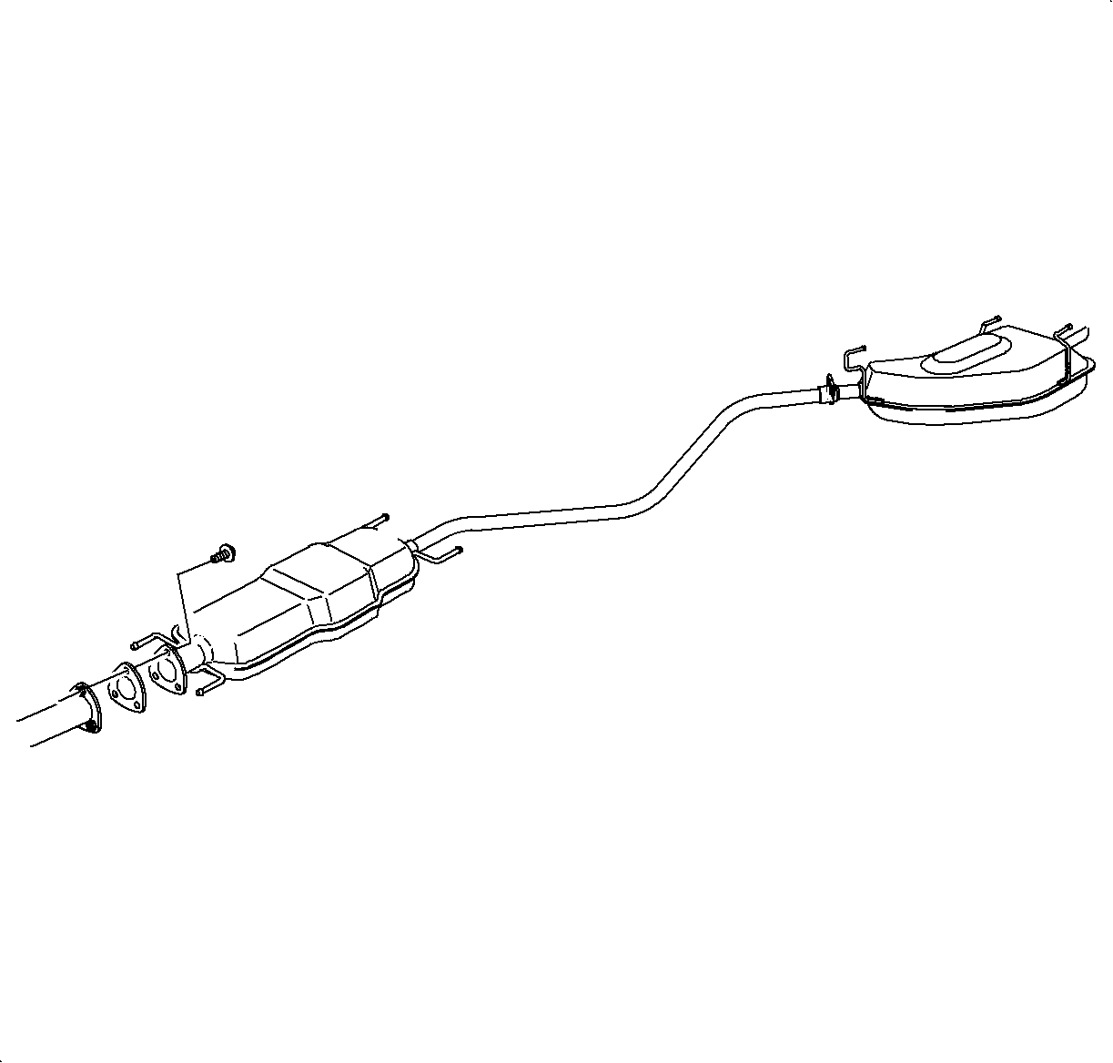
- Remove the rear exhaust system from the resonator back.
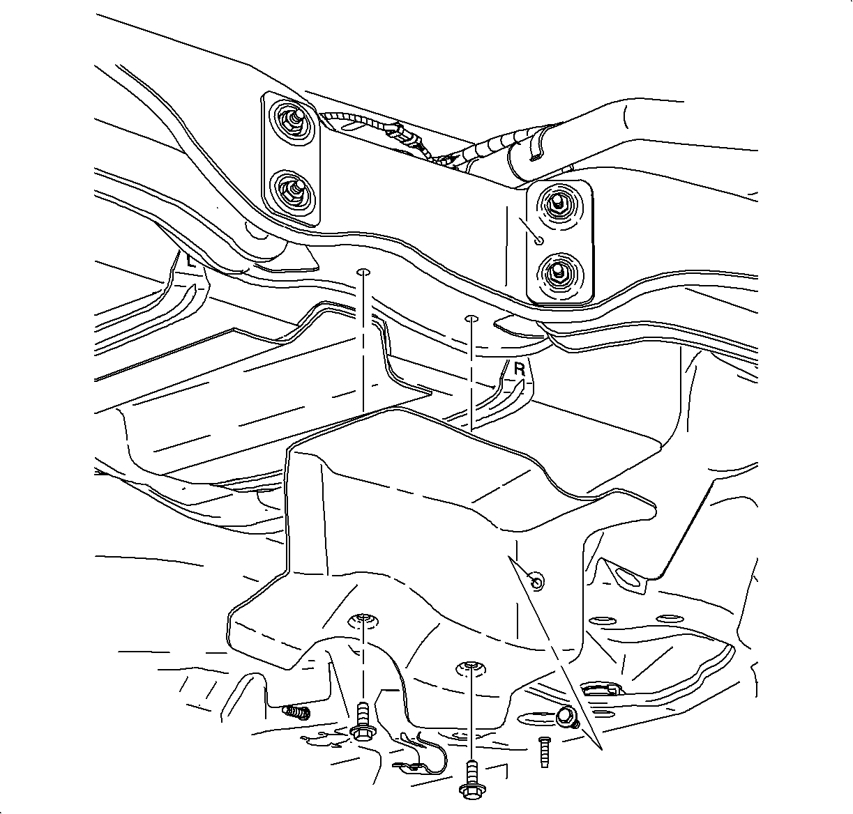
- Remove the heat shield from the rear suspension support.
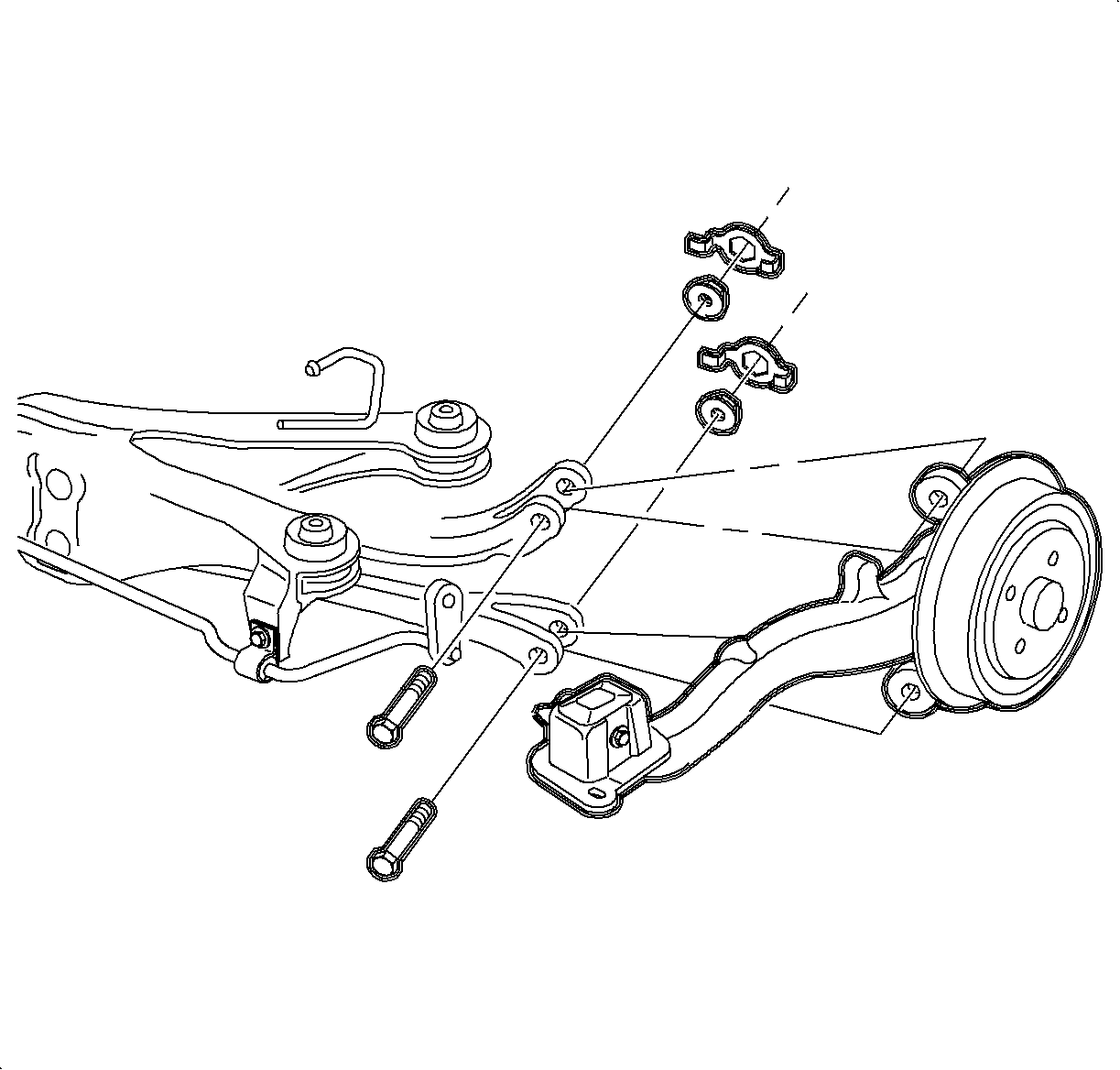
- Remove the upper and lower control arm to the rear axle control arm attachment bolts, discard the bolts and nuts.
- Remove the stabilizer bar links from the rear axle control arms.
- Support the rear suspension support with a suitable support stand.
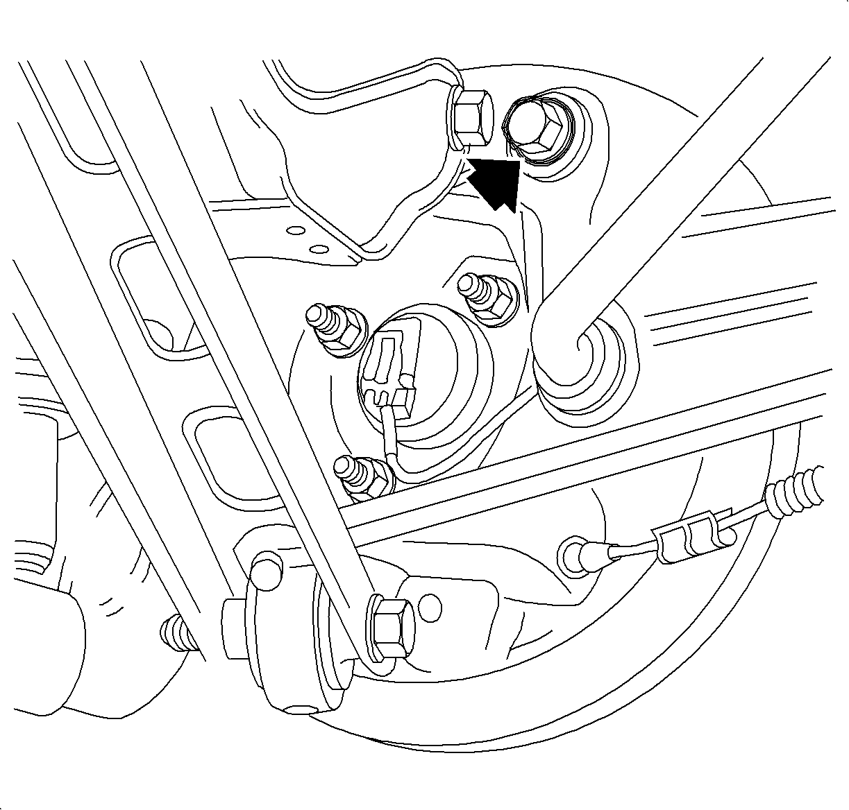
- Remove the 4 rear suspension support to body bolts and discard the bolts.
- Remove the rear suspension support from the vehicle.
Caution: Refer to Vehicle Lifting Caution in the Preface section.
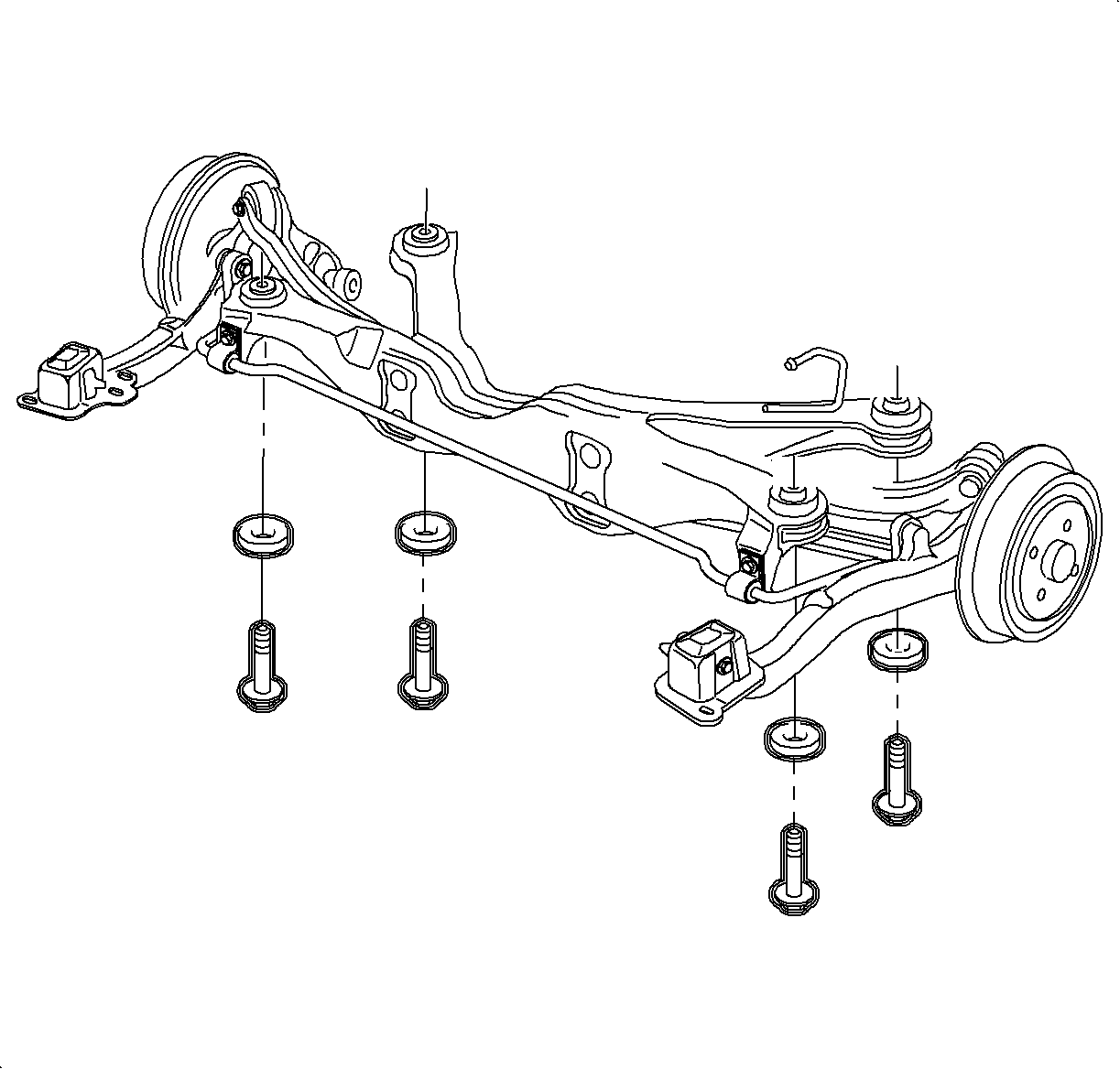
Caution: Failure to support crossmember can cause crossmember to drop to the ground when crossmember mounting bolts are removed.
Caution: Support the front of the vehicle to ensure that the vehicle will not become unbalanced and tip forward, off the hoist, once the rear crossmember is removed (due to decreased proportion of rear vehicle mass). Failure to support front of vehicle could cause vehicle to fall off hoist.
Installation Procedure
- Raise the rear suspension support assembly into the vehicle and install using new bolts.
- Install the upper and lower rear suspension control arms to the rear axle control arms using new nuts and bolts.
- Install the stabilizer links to the rear axle control arm.
- Install the heat shield to the rear suspension support.
- Install the rear exhaust system with the resonator attached.
- Position the wheel onto the hub.
- Install the wheel bolts and tighten in a star pattern.
- Lower the vehicle from the hoist.

Tighten
Tighten the rear suspension support-to-body bolts to 90 N·m (66 lb ft)
+ 90-105 degrees.

Tighten
Tighten the rear suspension control arm-to-knuckle to 90 N·m (66 lb ft)
+ 60-75 degrees.

Tighten
Tighten the rear stabilizer bar-to-knuckle to 55 N·m (41 lb ft).

Tighten
Tighten the heat shield-to-rear suspension support to 8 N·m (71 lb in).

Tighten
Tighten the exhaust manifold pipe-to-exhaust pipe bolts to 20 N·m
(15 lb ft).
Notice: Refer to Wheel Installation Caution in the Preface section.
| 7.1. | Hand tighten all 5 wheel bolts. |
| 7.2. | Use a torque wrench to tighten the wheel bolts using a star pattern |
Tighten
Tighten the wheel bolts first pass to 63 N·m (46 lb ft).
| 7.3. | Use a torque wrench to final tighten the wheel bolts using a star pattern. |
Tighten
Tighten the wheel bolts final pass to 125 N·m (92 lb ft).
