Tools Required
| • | KM-671 Bushing Remover/Installer |
| • | KM-906-B Bushing Remover/Installer |
Removal Procedure
- Raise the vehicle on the hoist.
- Remove the rear wheel and tire assembly.
- Remove the rear brake hose and bracket from the control arm.
- If equipped with rear disc brakes, remove the caliper mounting bolts.
- Remove the caliper. using mechanics wire, attach the caliper to the strut assembly.
- Remove the brake drum/rotor attachment screw.
- Remove the brake drum/rotor.
- If equipped, disconnect the ABS sensor harness.
- Remove the wheel hub-to-control arm nuts.
- Remove the hub from the vehicle.
- Disconnect the parking brake cable and remove the park brake cable support.
- Separate the backing plate from the control arm. Using mechanics wire, support the backing plate from the strut assembly.
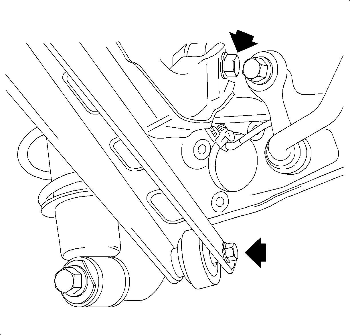
- Remove the shock absorber-to-control arm bolt and discard the bolt.
- Remove the rear stabilizer bar link-to-rear control arm bolt.
- Loosen the rear suspension upper and lower control arm-to-rear axle control arm fasteners. Do not remove.
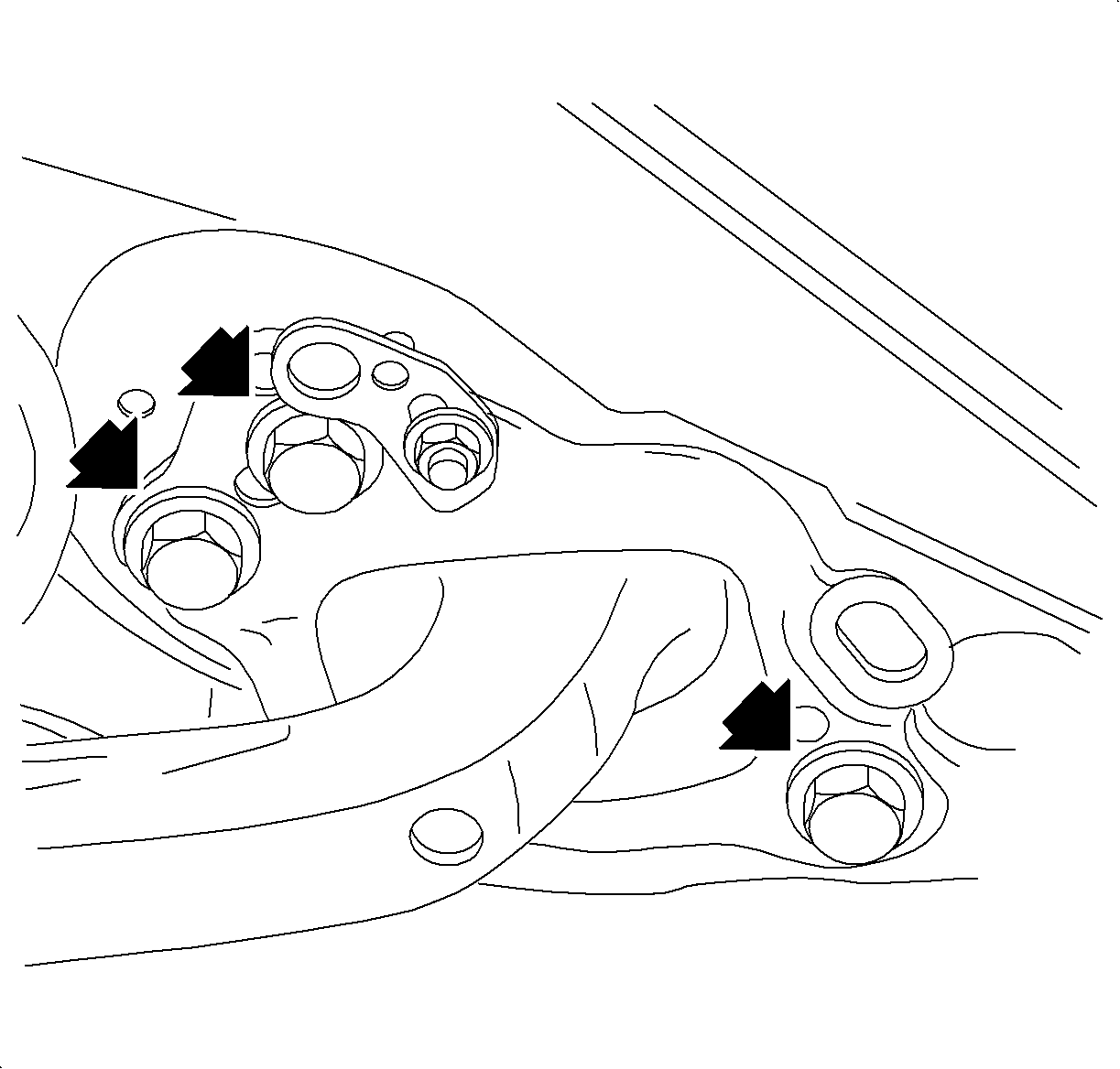
- Remove the rear axle control arm-to-body bolts and discard the bolts.
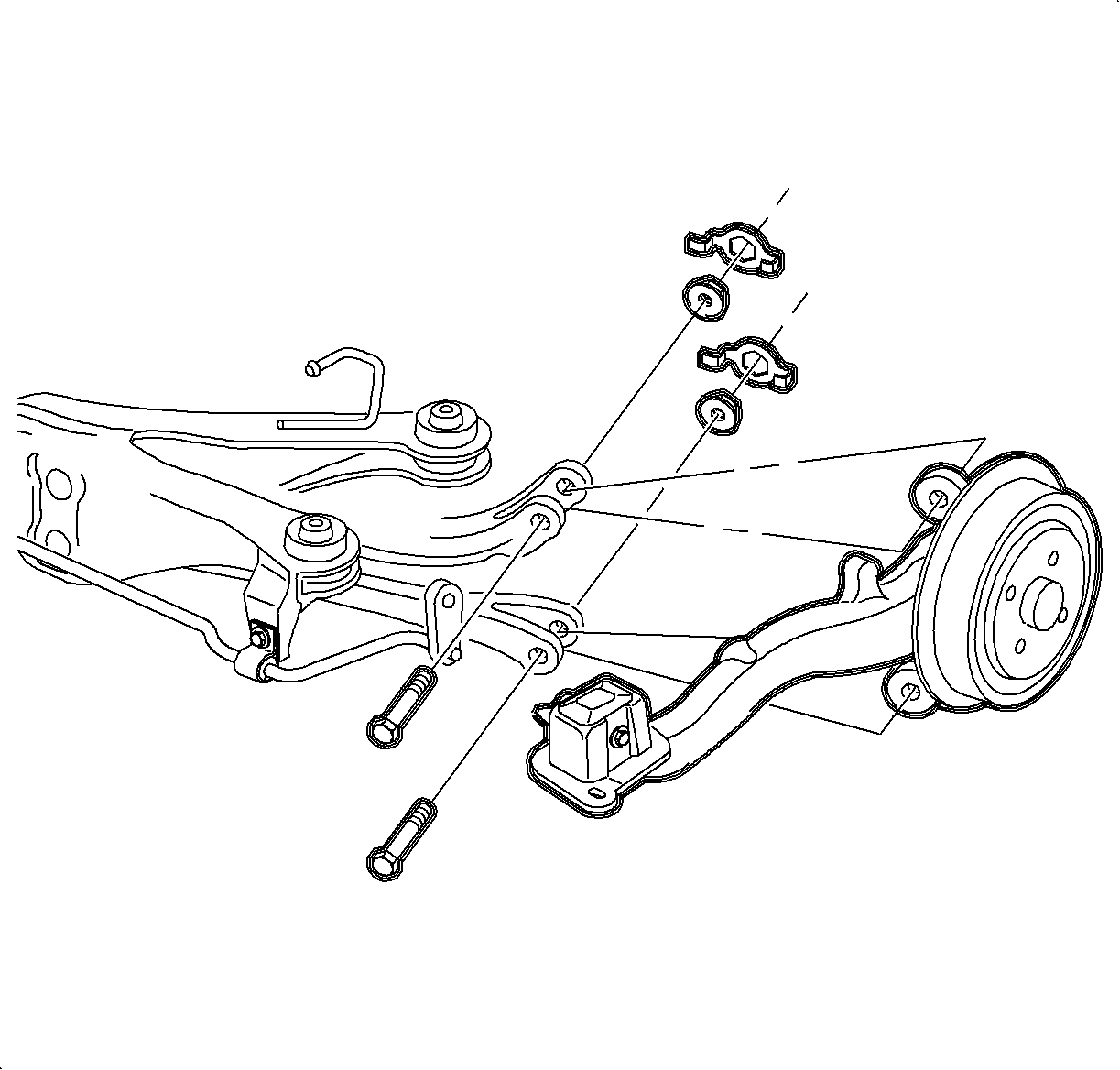
- Remove the upper and lower rear suspension control arm bolts and nuts. Discard the bolts and nuts.
- Remove the rear axle control arm from the vehicle.
Caution: Refer to Vehicle Lifting Caution in the Preface section.
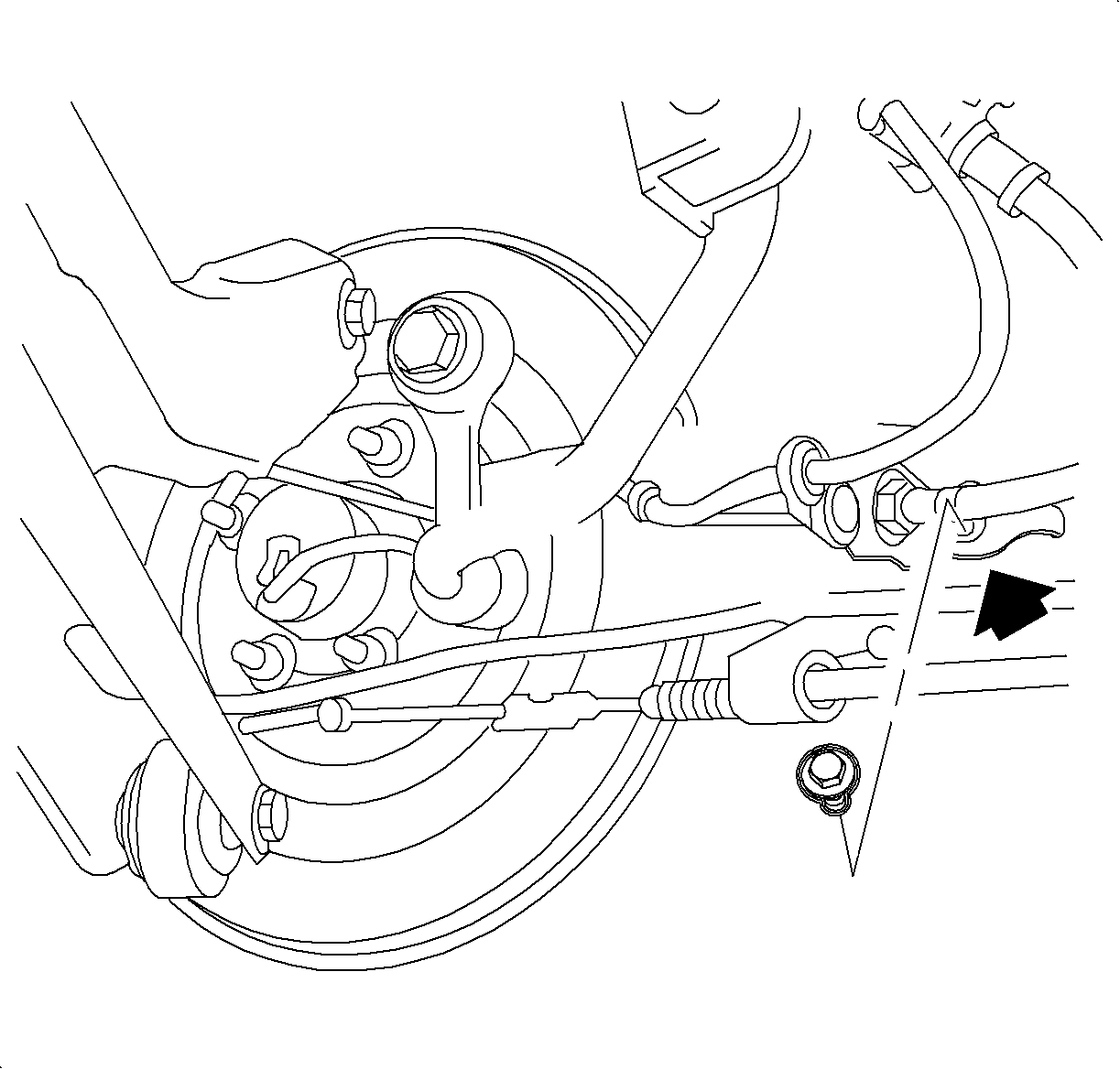
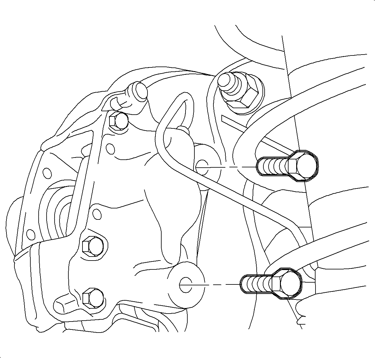
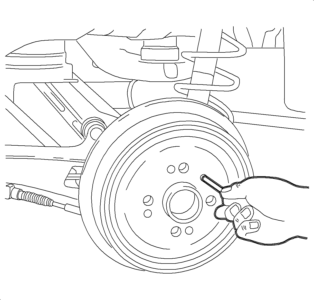
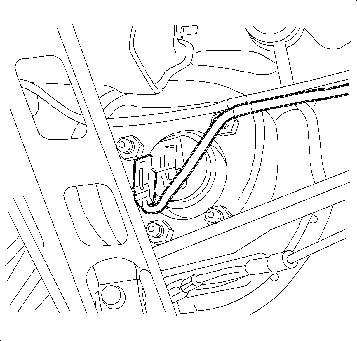
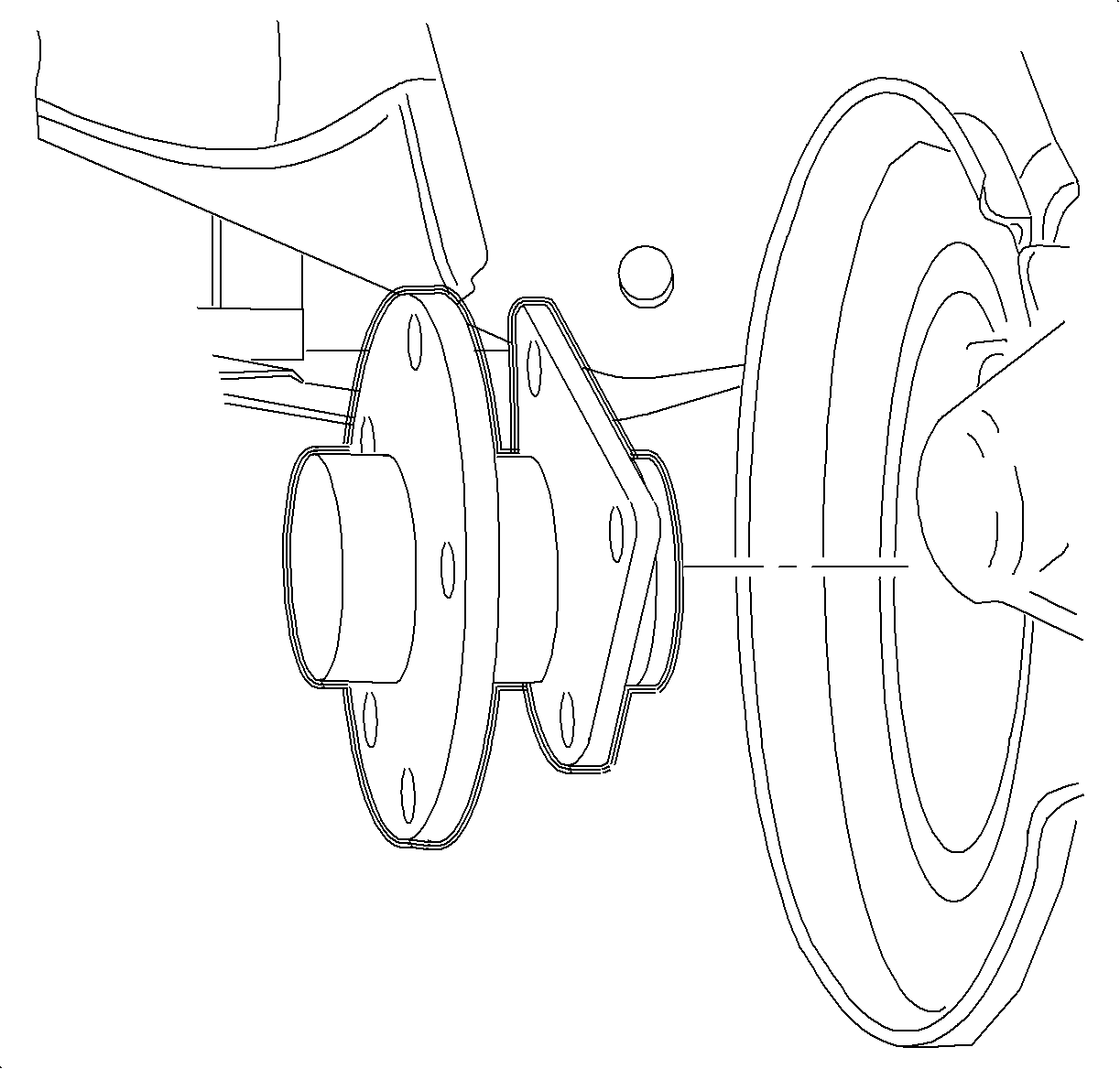
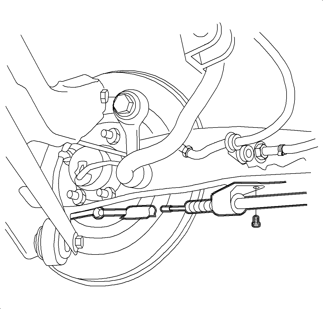
Important: Vehicles with drum brakes, do not remove the wheel cylinder. Be sure to flex the brake line at the rubber hose only.
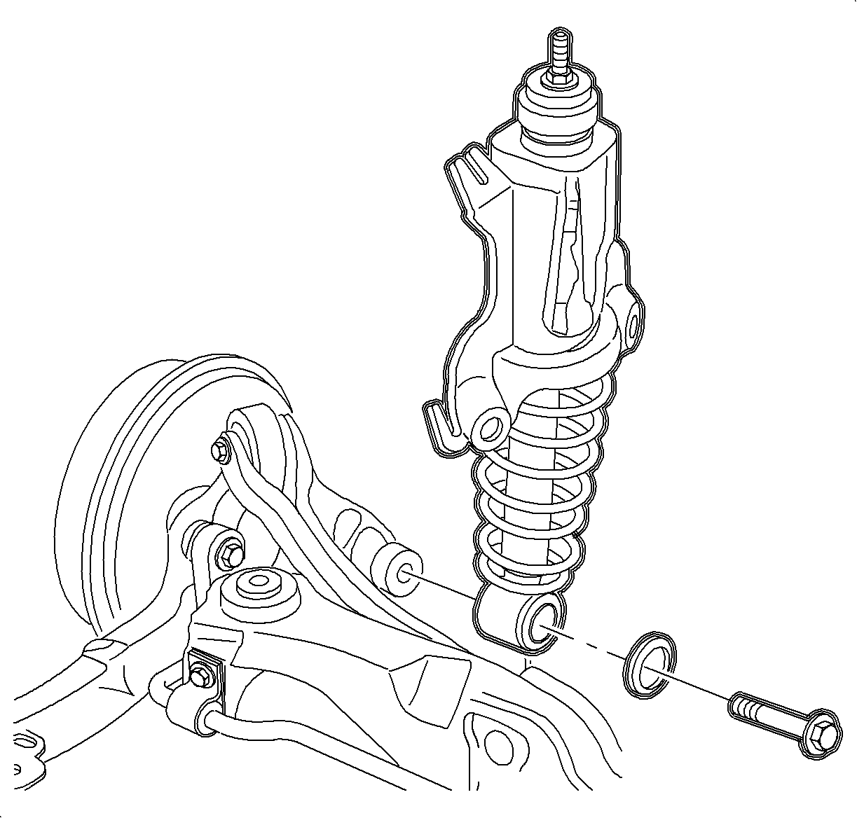
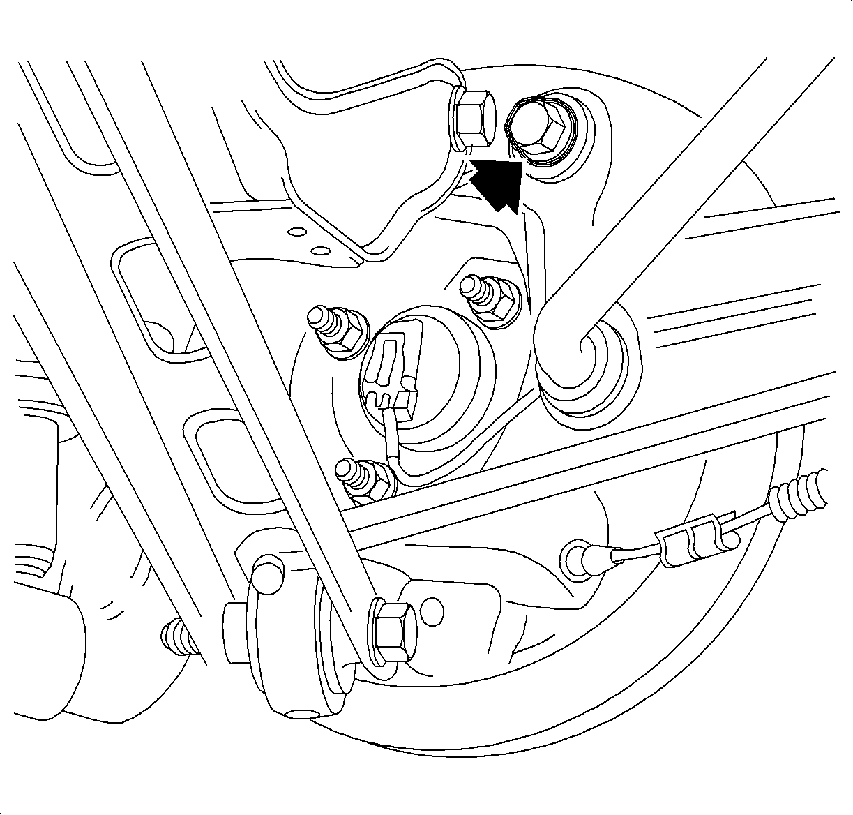
Installation Procedure
- Raise the control arm into the vehicle and install the new rear axle control arm bolts.
- Install the upper and lower rear suspension control arms to the rear axle control arm bracket using the NEW bolts and nuts.
- Tighten the rear axle control arm bracket-to-body bolts.
- Tighten the upper and lower control arm bolts to the rear axle control arm bracket.
- Install the shock absorber to the rear axle control arm using a new bolt.
- Install the stabilizer bar link to the control arm.
- Install the backing plat and the rear hub assembly to the control arm.
- Install the rear drum/rotors assembly.
- Install the rear drum/rotor attachment screw.
- If equipped with rear disc brakes, install the rear brake calipers-to-rear axle control arm bolts.
- Connect the park brake cable.
- Install the park brake cable support bracket.
- Install the brake line bracket to the control arm.
- Install the wheel and tire assemblies onto the hub.
- Install the wheel bolts and tighten in a star pattern.
- Perform the vehicle wheel alignment. Refer to Wheel Alignment Specifications in Wheel Alignment.

Important: A new nut and bolt must be used. Tighten retention of an old nut and bolt may not be sufficient.
Important: Do not tighten the fastener at this time.
Important: New nuts and bolts must be used. Tighten retention of the old nuts and bolts may not be sufficient.
Tighten
Tighten the rear axle control arm bracket-to-body bolts to 90 N·m
(66 lb ft) + 30-45 degrees.
Tighten
Tighten the rear suspension control arm-to-knuckle to 90 N·m (66 lb ft)
+ 60-75 degrees.

Important: New bolts must be used as tighten retention of the old bolts may not be sufficient.
Tighten
Tighten the rear shock absorber-to-knuckle bolt to 150 N·m (110 lb ft)
+ 30-45 degrees.

Tighten
Tighten the rear stabilizer bar-to-knuckle to 55 N·m (41 lb ft).

Tighten
Tighten the rear hub-to-knuckle to 50 N·m (37 lb ft)
+ 30-45 degrees.

Tighten
Tighten the rear brake drum-to-hub screw to 4 N·m (35 lb in).

Tighten
Tighten the rear caliper mounting bolts to 80 N·m (59 lb ft).

Tighten
Tighten the park brake cable-to-rear knuckle to 8 N·m (71 lb in).

Tighten
Tighten the rear brake line bracket-to-knuckle to 8 N·m (71 lb in).
Notice: Refer to Wheel Installation Caution in the Preface section.
| 15.1. | Hand tighten all 5 wheel bolts. |
| 15.2. | Use a torque wrench to tighten the wheel bolts using a star pattern. |
Tighten
Tighten the wheel bolts first pass to 63 N·m (46 lb ft).
| 15.3. | Use a torque wrench to final tighten the wheel bolts using a star pattern. |
Tighten
Tighten the wheel bolts final pass to 125 N·m (92 lb ft).
