Tools Required
J 45400 Strut Spring Compressor
Removal Procedure
- Raise the vehicle on the hoist.
- Remove the wheel and tire assemblies.
- Remove the brake hose and if equipped the ABS harness from the strut assembly.
- Loosen the steering knuckle to strut fasteners.
- Remove the stabilizer bar link to strut assembly attachment nut, and move the link toward the rear of the vehicle.
- Remove the strut assembly-to-body attachment nut.
- Remove the 2 steering knuckle to strut fasteners and discard the nut and bolt.
- Remove the strut assembly from the vehicle.
Caution: Refer to Vehicle Lifting Caution in the Preface section.
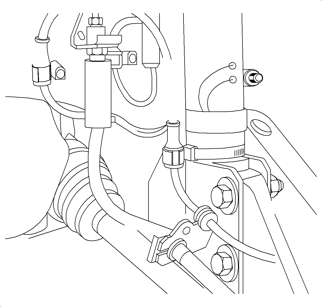
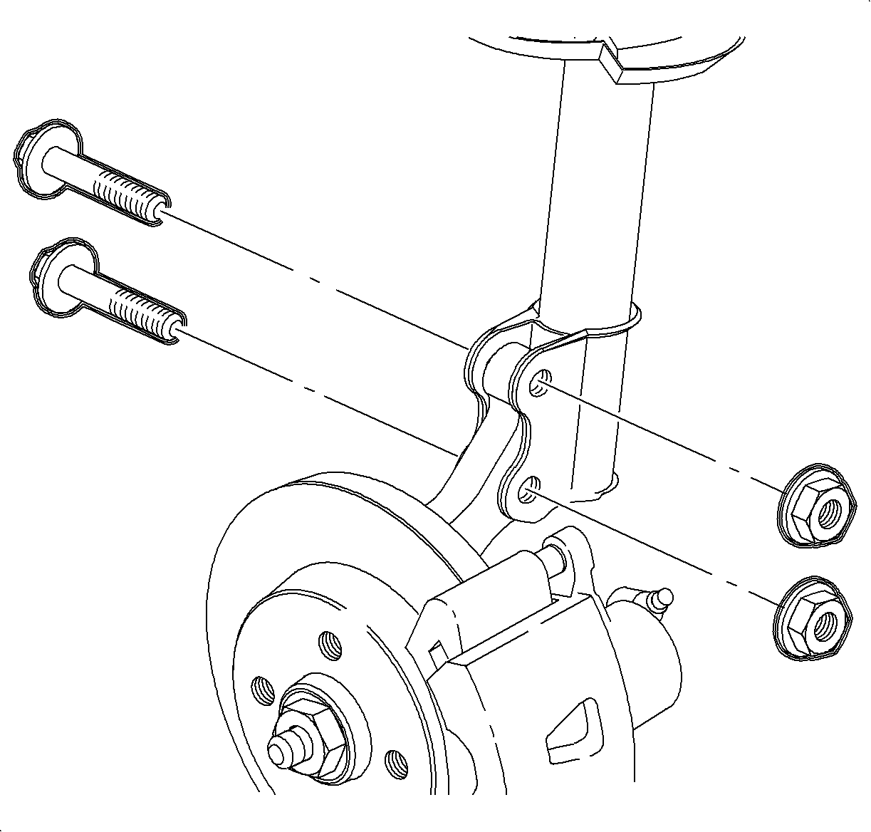
Important: Do not remove the fasteners at this time.
Notice: Refer to Ball Stud Turning Notice in the Preface section.
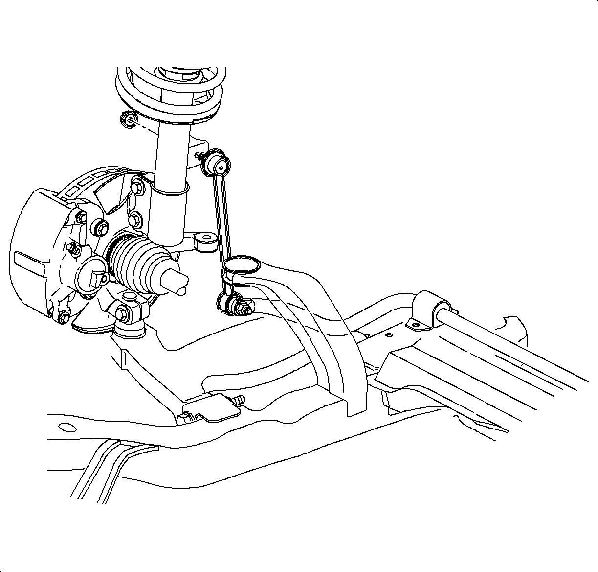
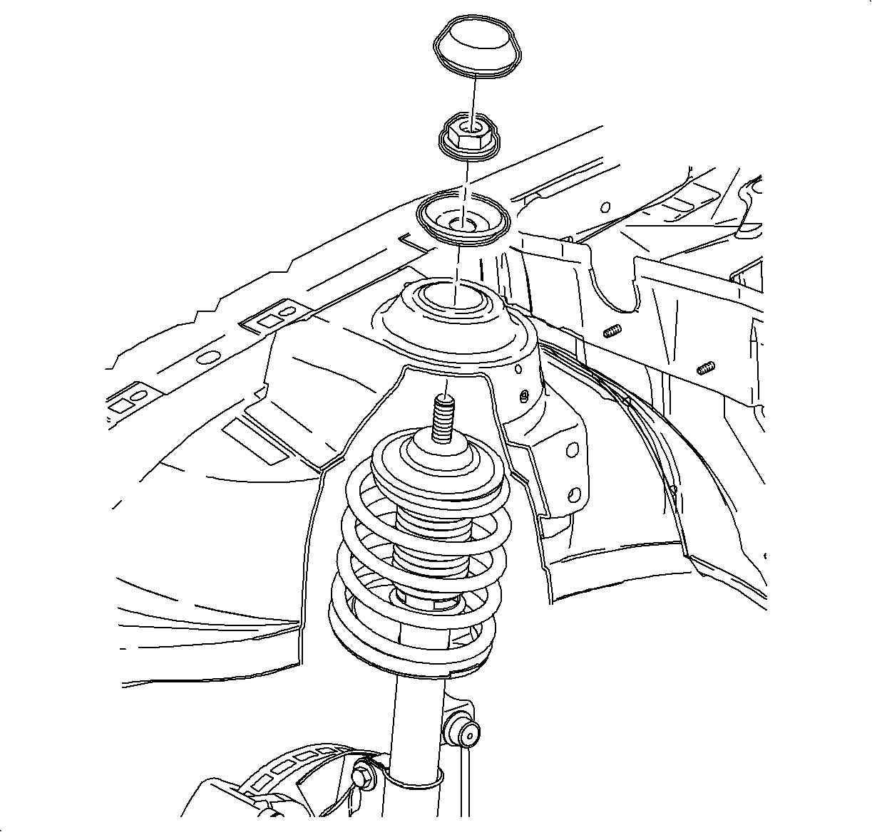
Notice: Before removing strut assembly, place a rag over the CV joint boot to protect it from damage.
Disassembly Procedure
- Mount the J 45400 or equivalent, in the holding fixture.
- Place the strut/spring assembly into the spring compressor. Fasten the strut with a strut to knuckle bolt and nut through the lower strut mounting hole.
- Compress the spring enough to completely unload the upper strut mount.
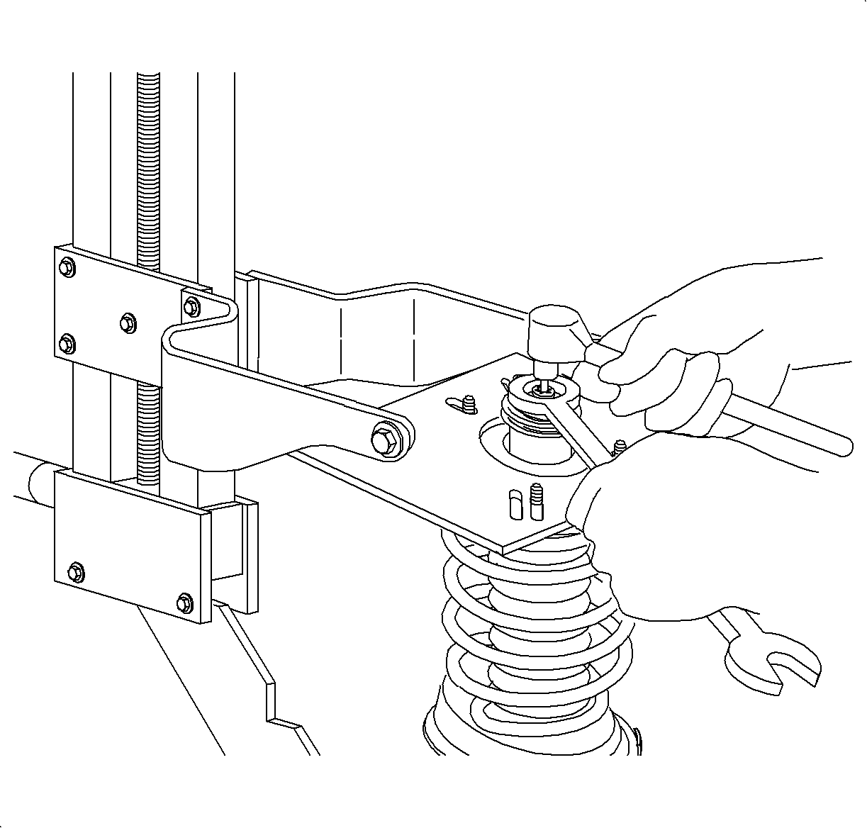
- Remove the strut shaft nut with a wrench, while holding the strut shaft stationary with a TORX™ socket.
- Release the spring compressor and tilt the strut assembly outward.
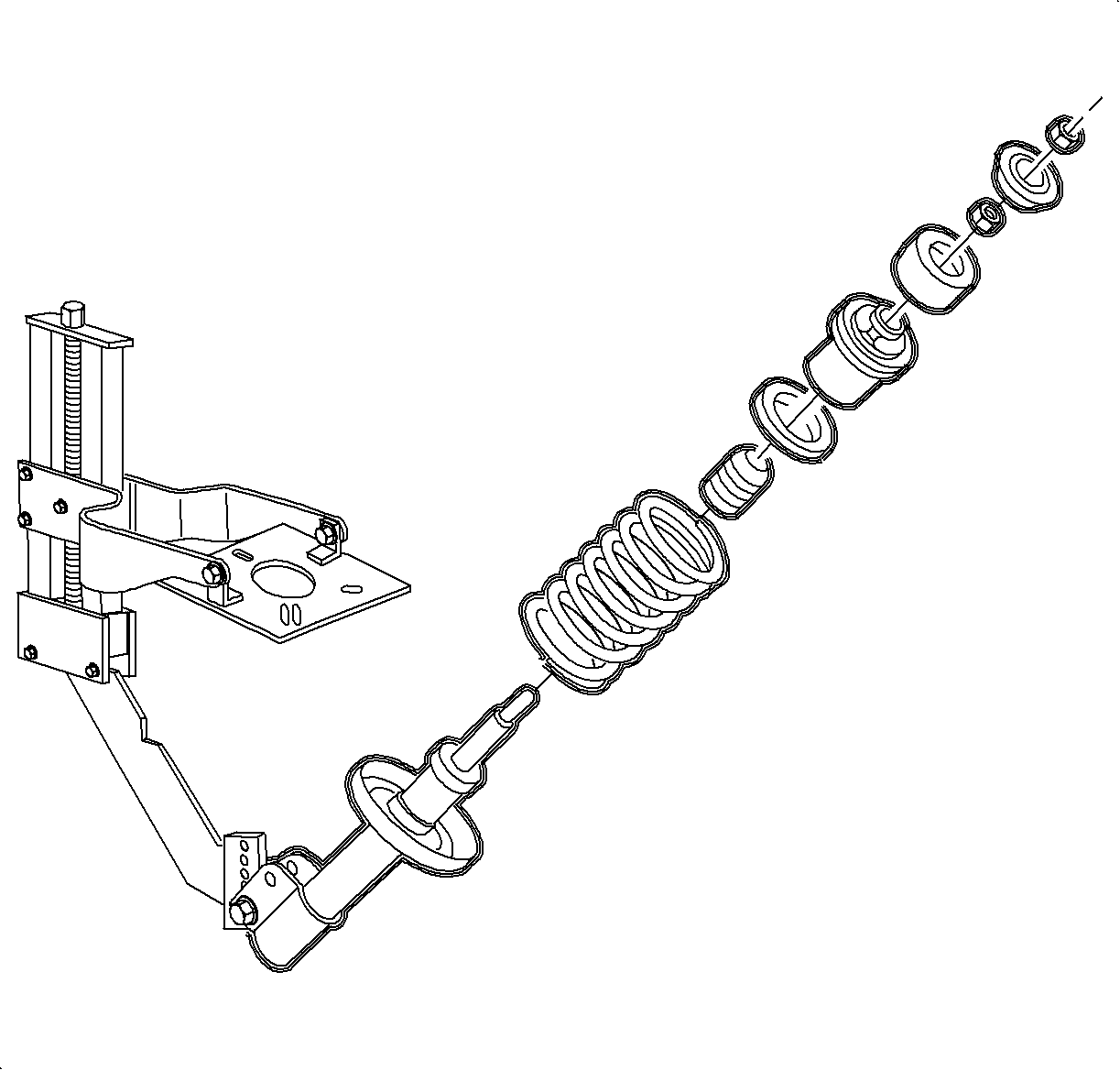
- Remove the upper strut mount assembly. Inspect the rubber for cracks or deterioration. Rotate the upper support bearing by hand and check for smooth operation.
- Remove the strut spring from the strut. Inspect the spring for damage.
- Remove the hollow bumper. Inspect for cracks or deterioration.
- Remove the strut from the compressor. Extend and retract the strut shaft and check for smooth, even resistance.
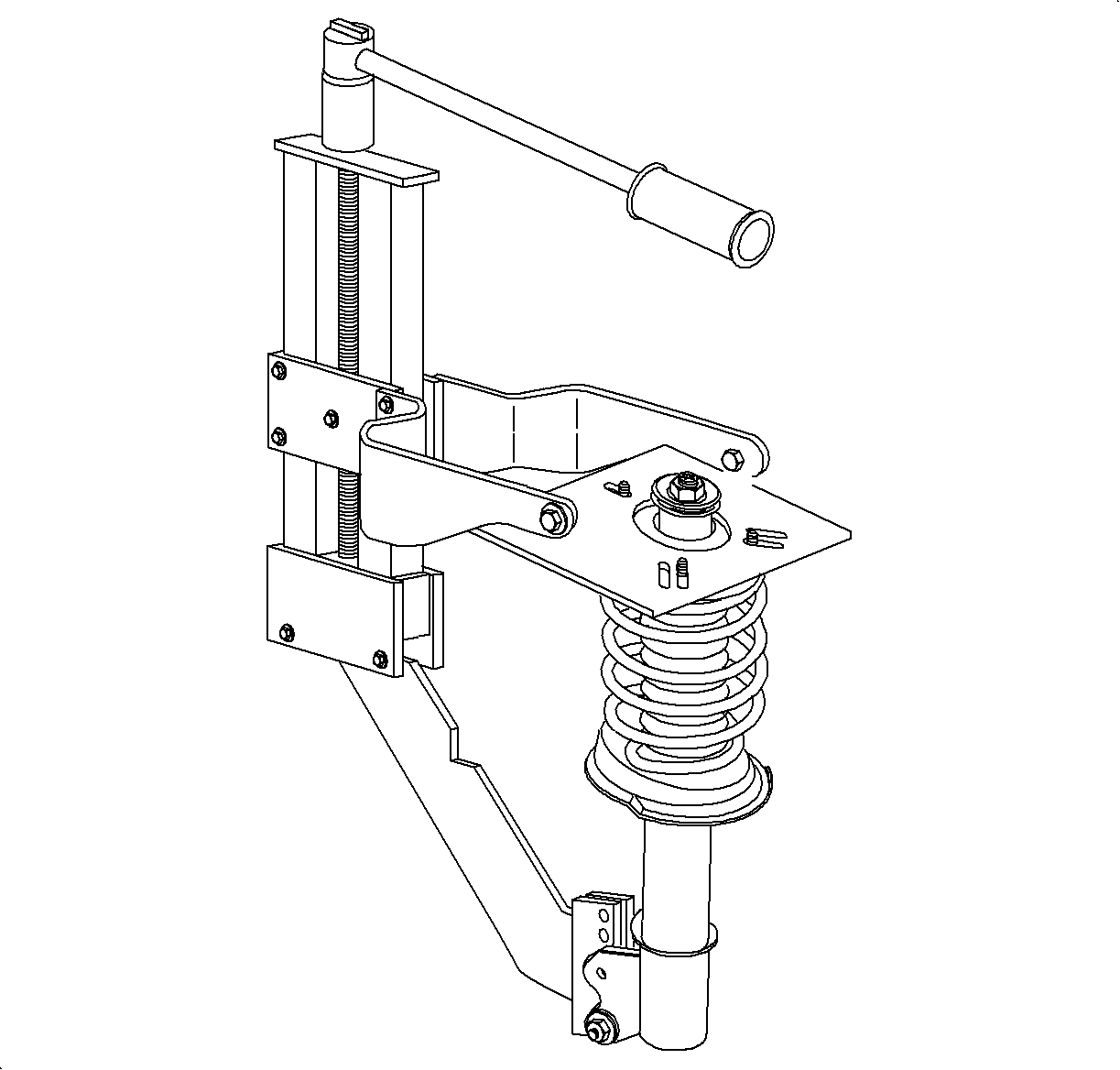
Caution: Strut spring is under a high compressive load. Do not remove the strut shaft to upper support nut without first relieving the upper and lower spring supports of spring pressure, using the proper spring compressing tool.
Assembly Procedure
- Place the strut into the spring compressor. Fasten the strut with a strut-to-knuckle bolt and nut through the lower mounting hole.
- Extend the strut shaft to the limit of its travel.
- Place the hollow bumper onto the strut assembly.
- Install the spring onto the strut.
- Install the upper spring seat and strut mount.
- Compress the spring while guiding the strut shaft through the upper strut mount assembly until the upper washer and shaft nut can be installed onto the shaft. Do not over-compress the spring.
- Tighten the strut shaft nut with a wrench while holding the strut shaft with a TORX™ socket.
- Release the spring compressor tool.
- Remove the strut from the compressor.
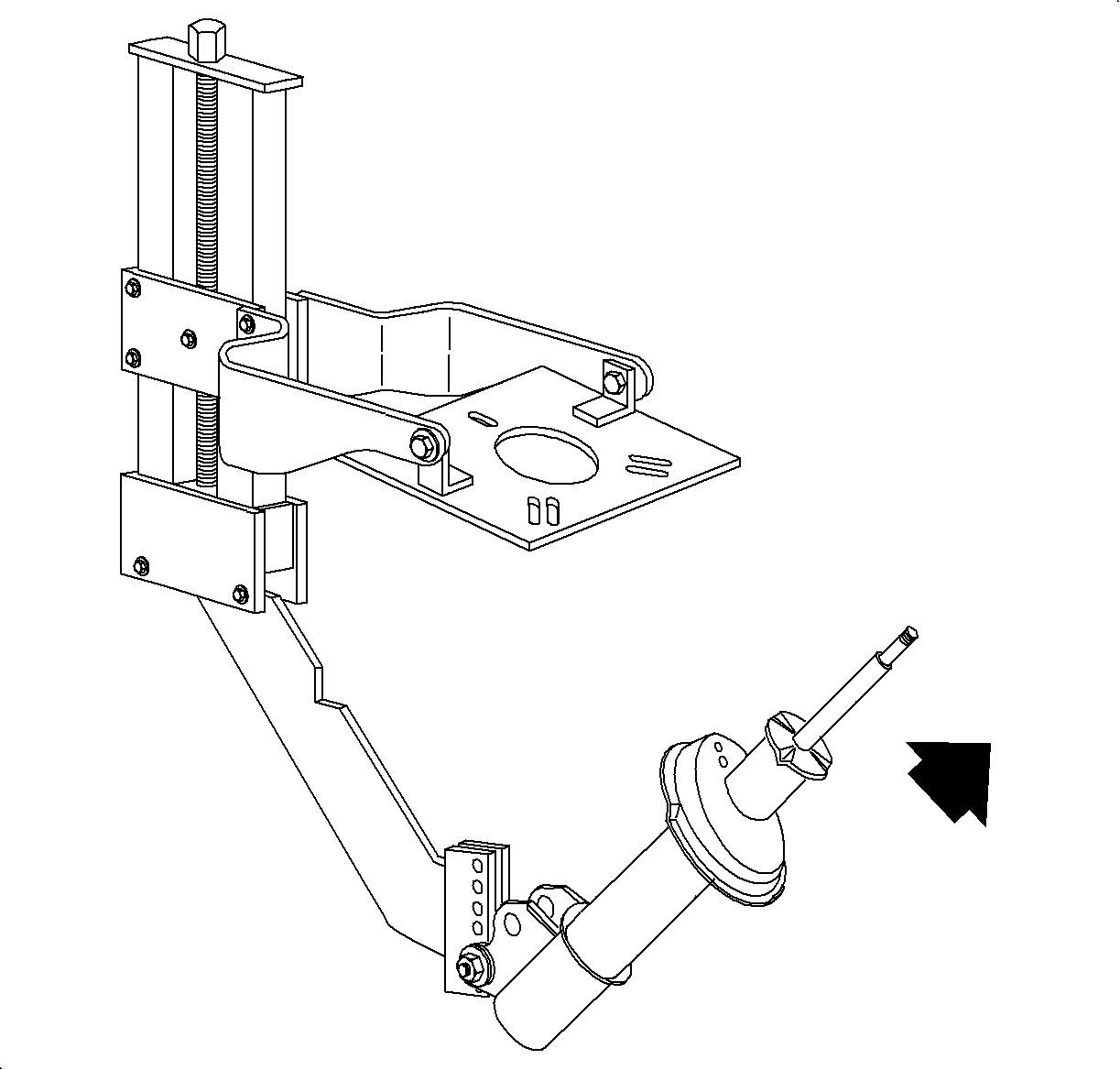

Important: Make sure the spring is correctly positioned in the spring seat and isolator.
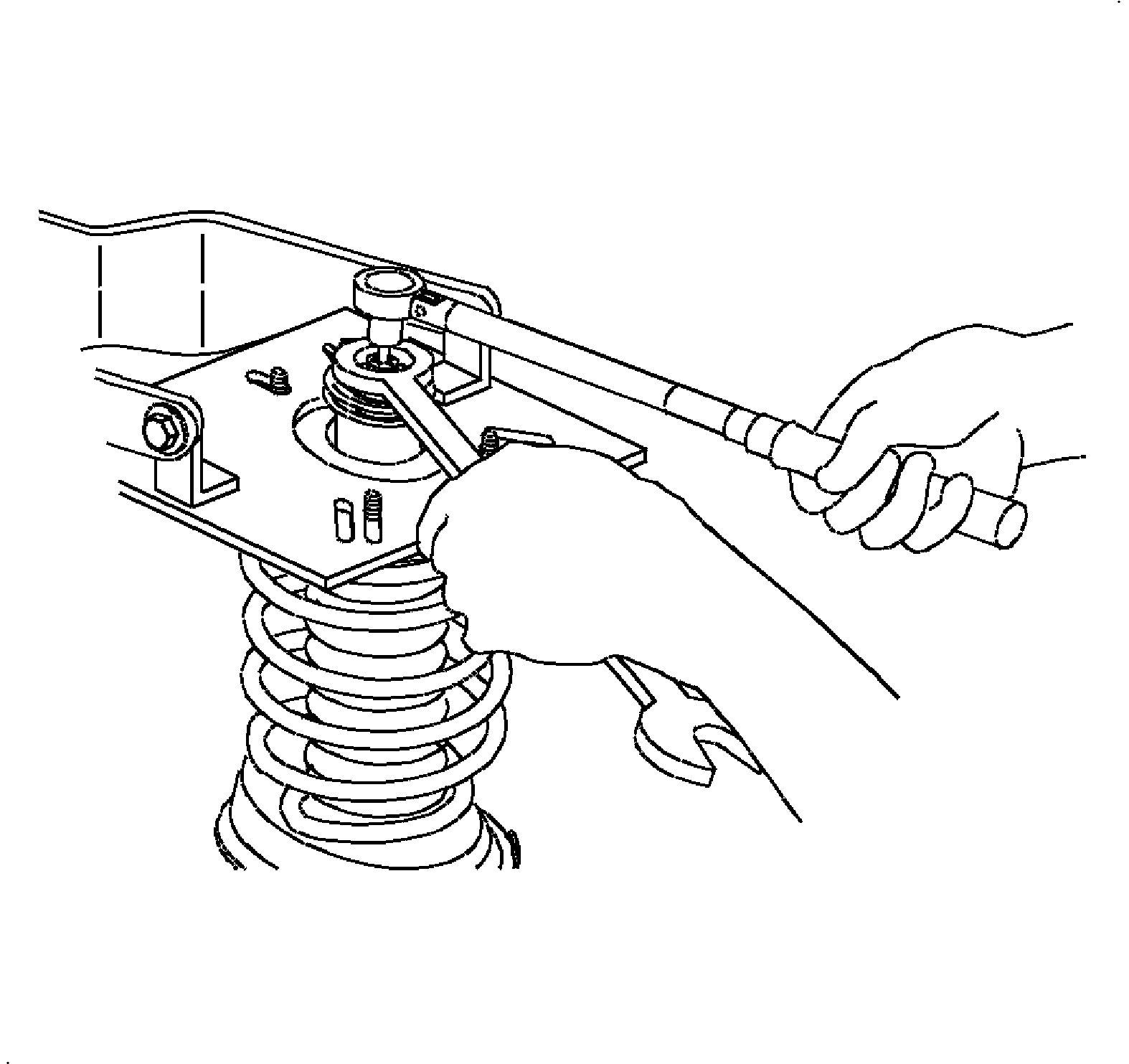
Tighten
Tighten the spring seat nut-to-front strut shaft to 55 N·m (40 lb ft).
Installation Procedure
- Attach the strut to vehicle body with the strut stop and strut-to-body attachment nut.
- Attach the strut to steering knuckle with the fasteners.
- Tighten the front strut-to-knuckle initial pass to 50 N·m (37 lb ft).
- Tighten the front strut-to-knuckle final pass to 100 N·m (73 lb ft) + 30-40 degrees.
- Install the stabilizer bar link to the strut assembly.
- Inspect the boots for damage and replace if damaged.
- Reattach the brake hose, and ABS wiring to the strut, if the vehicle is equipped.
- Position the wheel onto the hub.
- Install the wheel bolts and tighten in a crisscross pattern.
- Lower the vehicle from the hoist.
- Perform the vehicle wheel alignment. Refer to Wheel Alignment Specifications in Wheel Alignment.

Important: Use a new nut. The tighten retention of the old nut may not be sufficient.
Tighten
Tighten the front strut-to-body upper nut to 55 N·m (40 lb ft).

Important: New nuts and bolts must be used. The tighten retention of old nuts and bolts may not be sufficient.
Tighten
Notice: Refer to Ball Stud Turning Notice in the Preface section.

Tighten
Tighten the stabilizer bar link-to-strut to 65 N·m (48 lb ft).

Notice: Refer to Wheel Installation Caution in the Preface section.
| 7.1. | Hand tighten all five wheel bolts. |
| 7.2. | Us a torque wrench to tighten the wheel bolts using a crisscross pattern. |
Tighten
Tighten the wheel bolts first pass to 63 N·m (46 lb ft).
| 7.3. | Use a torque wrench to final tighten the wheel bolts using a crisscross pattern. |
Tighten
Tighten the wheel bolts final pass to 125 N·m (92 lb ft).
