Removal Procedure
Important: The rear wheel speed sensor is contained within the hub/bearing assembly. The sensor is not serviceable separately. To replace a damaged rear wheel speed sensor, the entire rear hub/bearing assembly must be replaced.
Caution: Ensure that the vehicle is properly supported and squarely positioned. To help avoid personal injury when a vehicle is on a hoist, provide additional support for the vehicle on the opposite end from which the components are being removed.
- Raise the vehicle on a hoist.
- Remove the rear wheel and the tire assembly corresponding to the hub being replaced.
- Disconnect the electrical connector from the ABS wheel speed sensor.
- For vehicles equipped with rear disc brakes, perform the following:
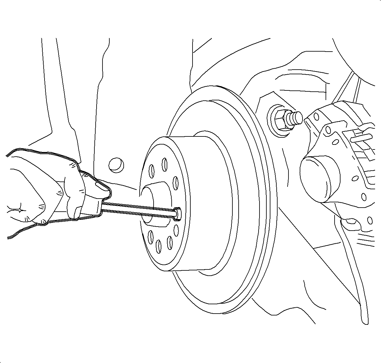
- Remove the drum/rotor retaining screw.
- Remove the drum/rotor.
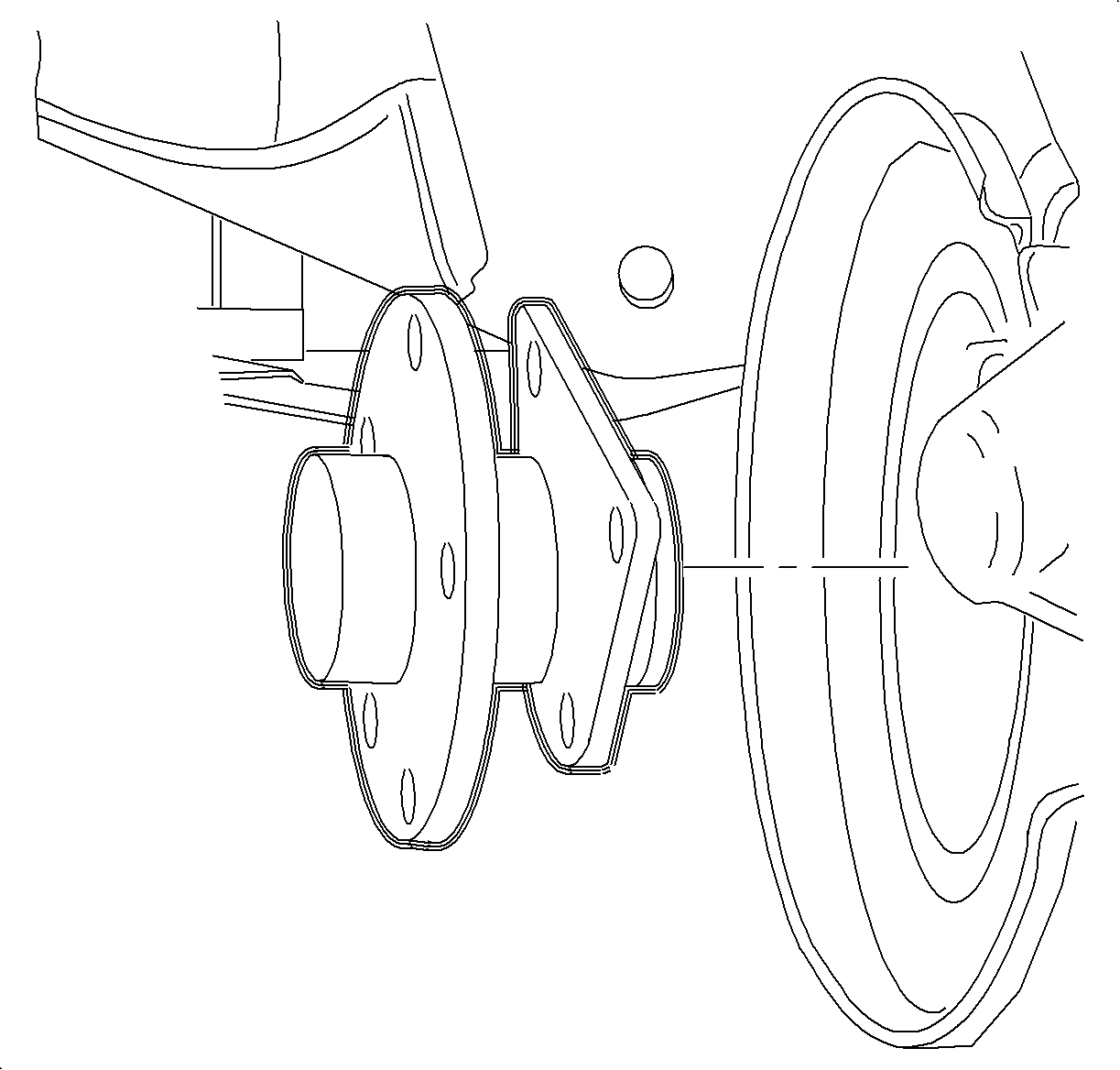
- Remove the hub-to-rear axle control arm attachment nuts. Discard the nuts.
- Remove the hub/bearing assembly.
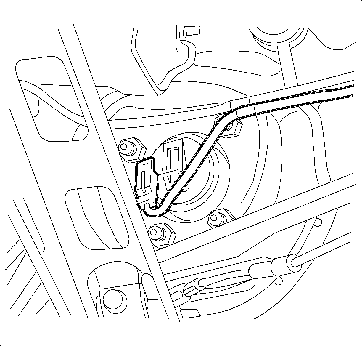
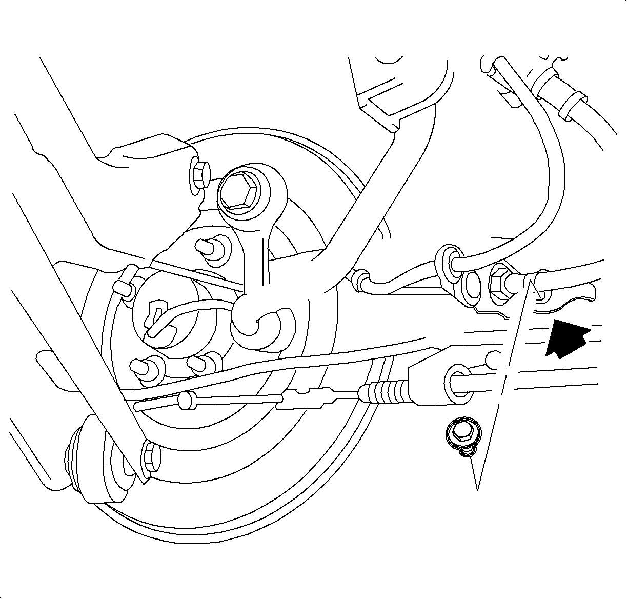
| 4.1. | Remove the brake pipe to control arm support bracket. |
| 4.2. | Remove the caliper-to-knuckle fasteners. |
| 4.3. | Remove the caliper, and it hang from the strut spring with mechanic's wire. |
Installation Procedure
- Install the hub and brake shield to the rear axle control arm with new nuts.
- Install the brake rotor/drum and tighten the retaining screw.
- On vehicles equipped with rear disc brakes, perform the following steps:
- Install the caliper to the rear axle control arm, and tighten the fasteners.
- Connect the brake pipe support bracket to the control arm.
- Connect the ABS sensor electrical connector.
- Position the wheel and tire the assembly onto the hub.
- Install wheel bolts and tighten in a crisscross pattern.
- Use a torque wrench to final tighten the wheel bolts using a crisscross pattern.
- Lower the vehicle from the hoist.
- Program the EBTCM with the correct engine and transaxle options or DTC C0551 will set and the traction control will not operate.
Notice: Refer to Fastener Notice in the Preface section.

Important: New nuts must be used as torque retention of old nuts may not be sufficient.
Tighten
Tighten the rear hub assembly-to-knuckle nuts to 50 N·m (37 lb ft)
+ 30-45 degrees.

Tighten
Tighten the brake drum retaining fastener to 4 N·m (35 lb in).
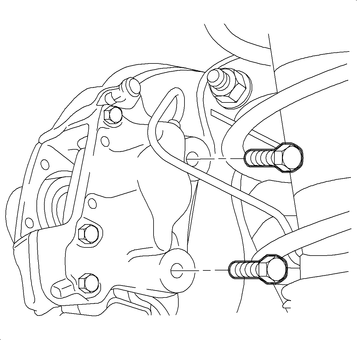
| 3.1. | Clean the caliper support bracket fasteners thoroughly with brake and choke cleaner P/N 21007432 or equivalent. |
| Important: If Loctite 272® Threadlocker or equivalent is not available, new caliper support bracket fasteners must be used. |
| 3.2. | Apply LOCTITE 272® Threadlocker or equivalent to the caliper support bracket fasteners. |
Tighten
Tighten the rear caliper-to-rear axle control arm to 80 N·m (59 lb ft).

Tighten
Tighten the brake pipe bracket-to-rear control arm to 8 N·m (71 lb in).

Important: Be sure that the electrical connections are fully seated and the latch is engaged.
Notice: Before installing wheels, remove rust or corrosion from wheel mounting surfaces and brake rotors/drums. Failure to do so can cause wheel nuts to loosen in service.
| 8.1. | Hand tighten all 5 wheel bolts. |
| 8.2. | Use a torque wrench to tighten the wheel bolts using a crisscross pattern. |
Tighten
Tighten the wheel bolts (initial tighten) to 63 N·m (46 lb ft).
Tighten
Tighten the wheel bolts (final tighten) to 125 N·m (92 lb ft).
