For 1990-2009 cars only
Removal Procedure
- Disable the SIR system. Refer to Disabling the SIR System in SIR.
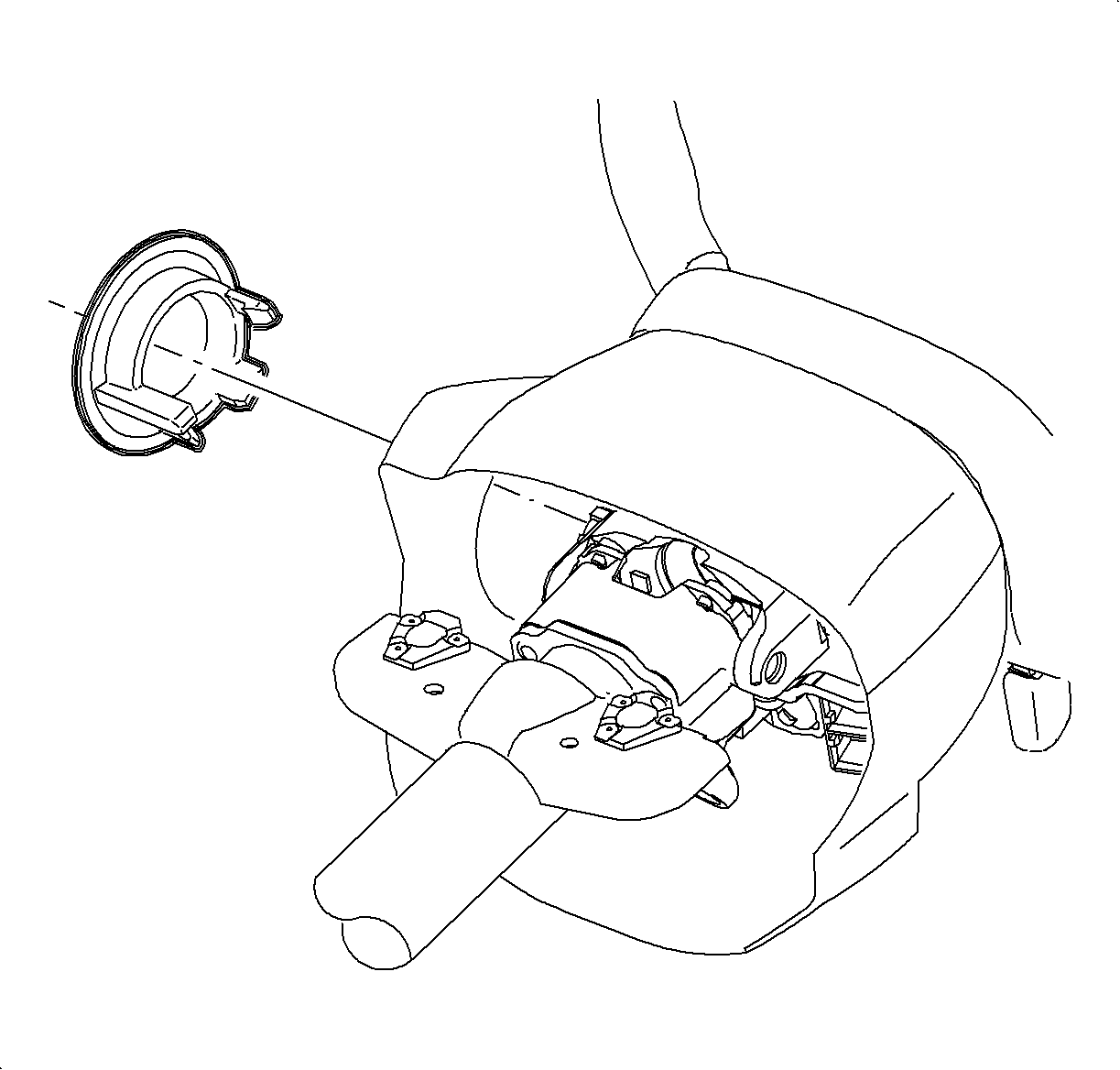
- Remove the lock cylinder bezel from the steering column shroud by carefully prying with a thin bladed screwdriver.
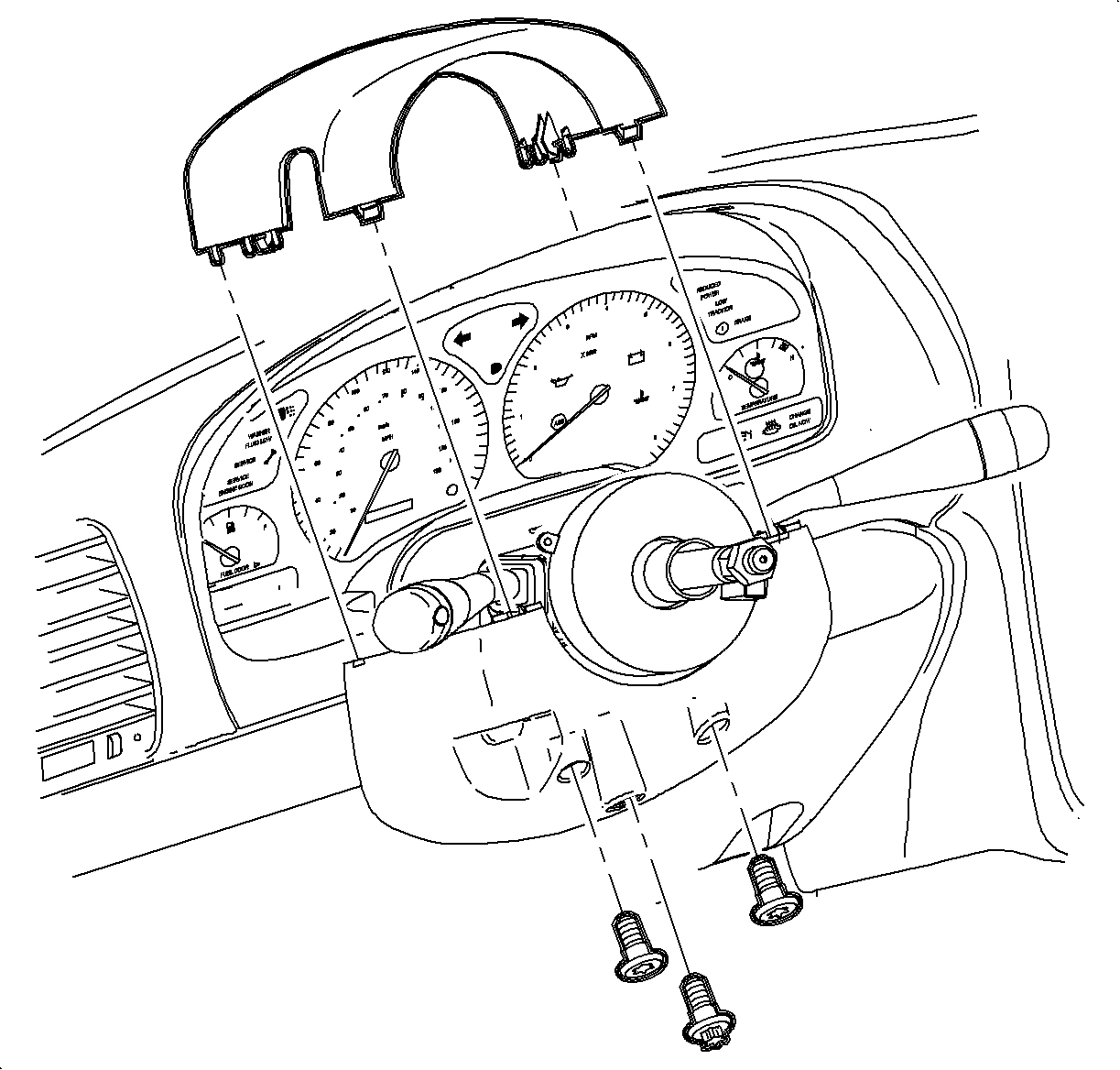
- Remove the steering column upper shroud panel.
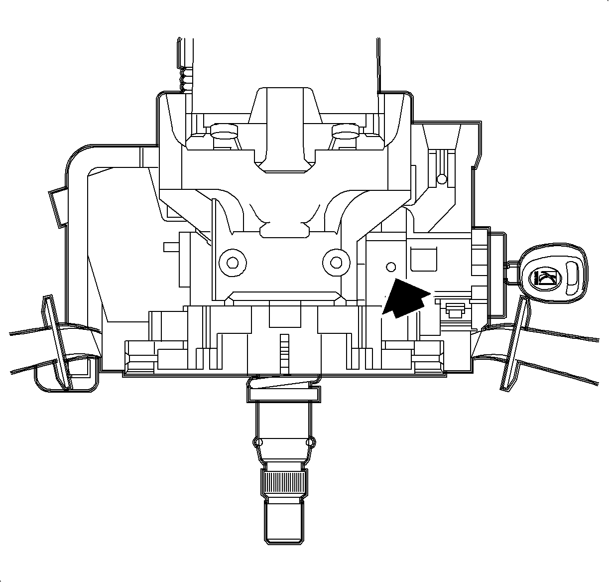
- Insert the key into the ignition lock cylinder and rotate it to the START position. Then, rotate the cylinder back to the RUN position.
- Depress the locking button on the top of the ignition module assembly with a thin pic-type tool. Slide the lock cylinder assembly from the ignition module.
- Remove the shroud fasteners and remove the steering column lower shroud panel.
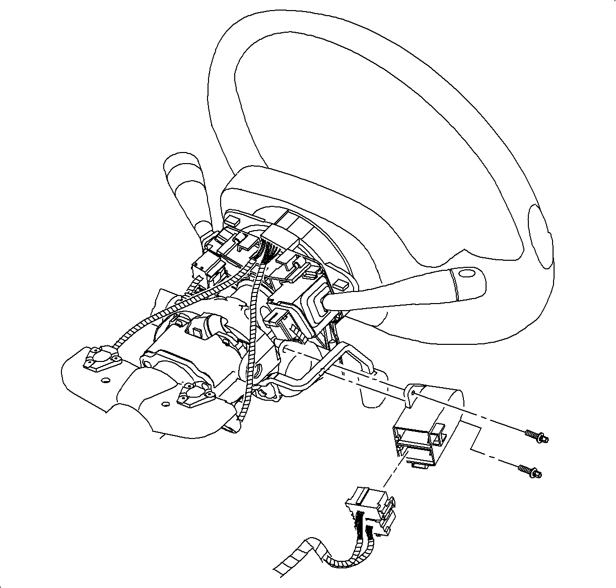
- Disconnect the ignition switch connector and remove the ignition switch from the ignition module.
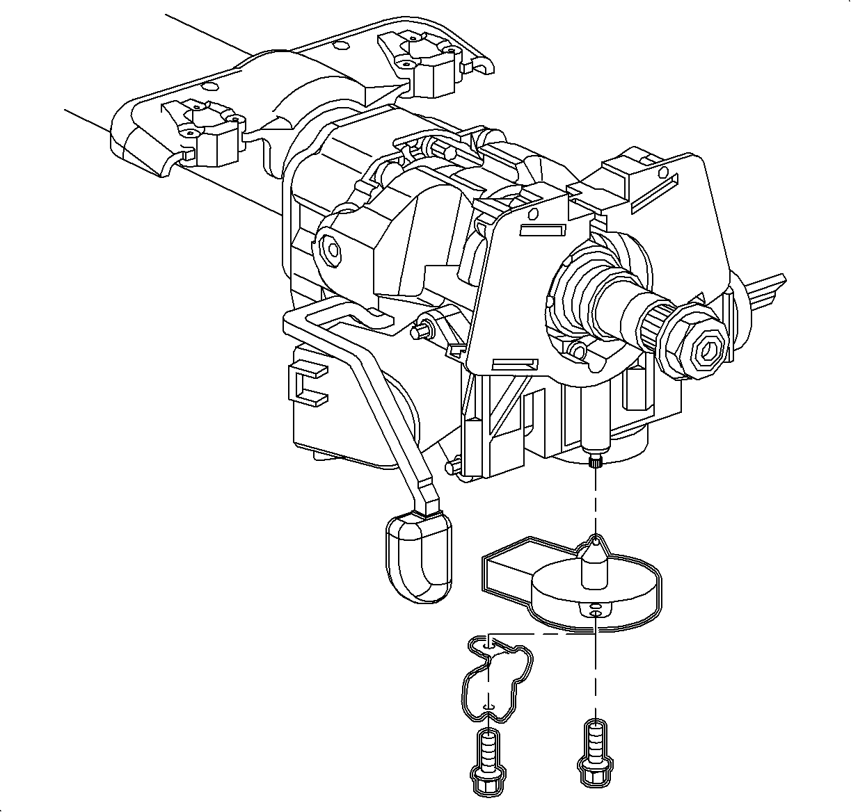
- Remove the park lock solenoid.
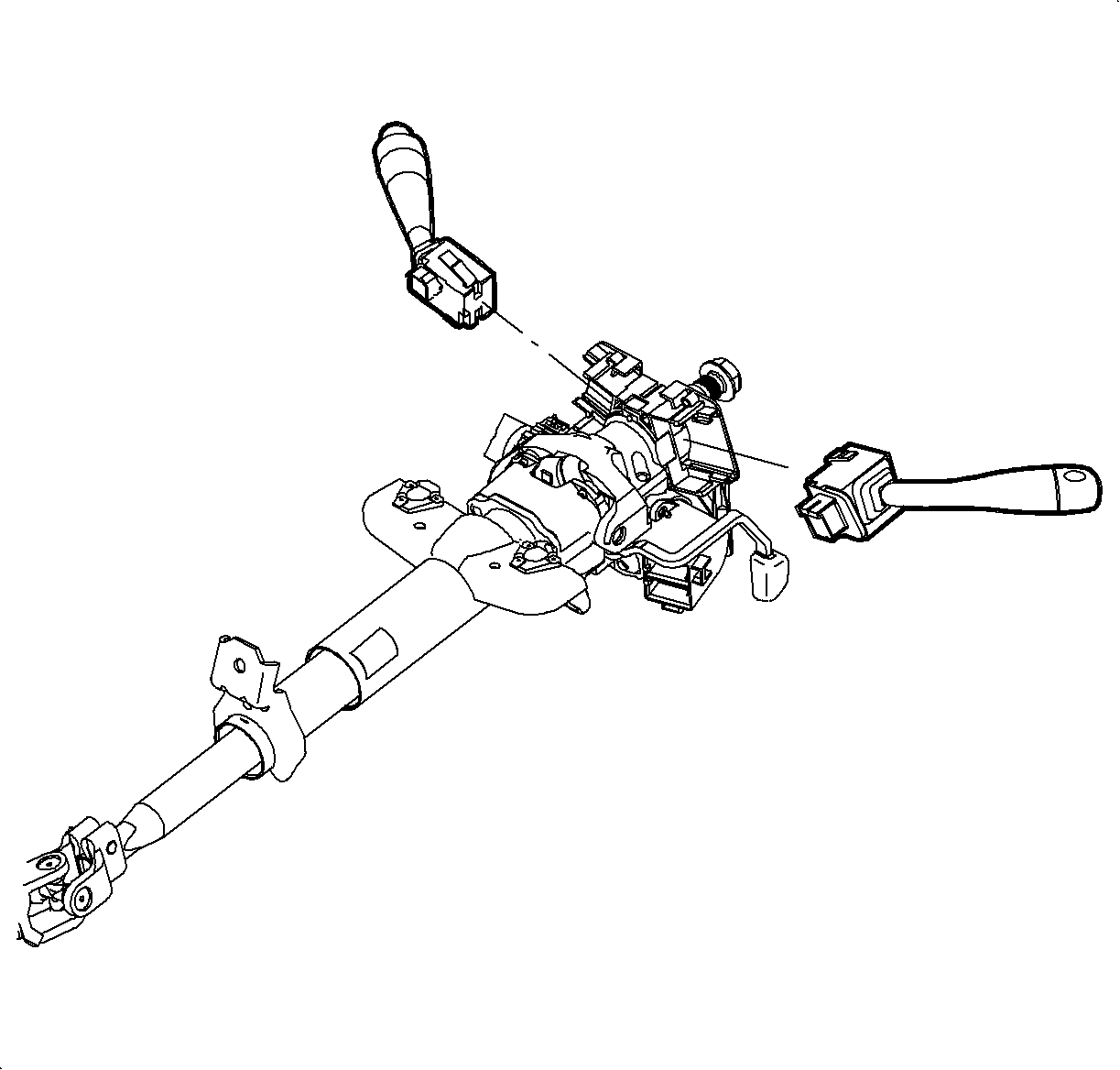
- Remove the turn signal/headlamp lever, the windshield washer lever, and the passlock sensor connector.
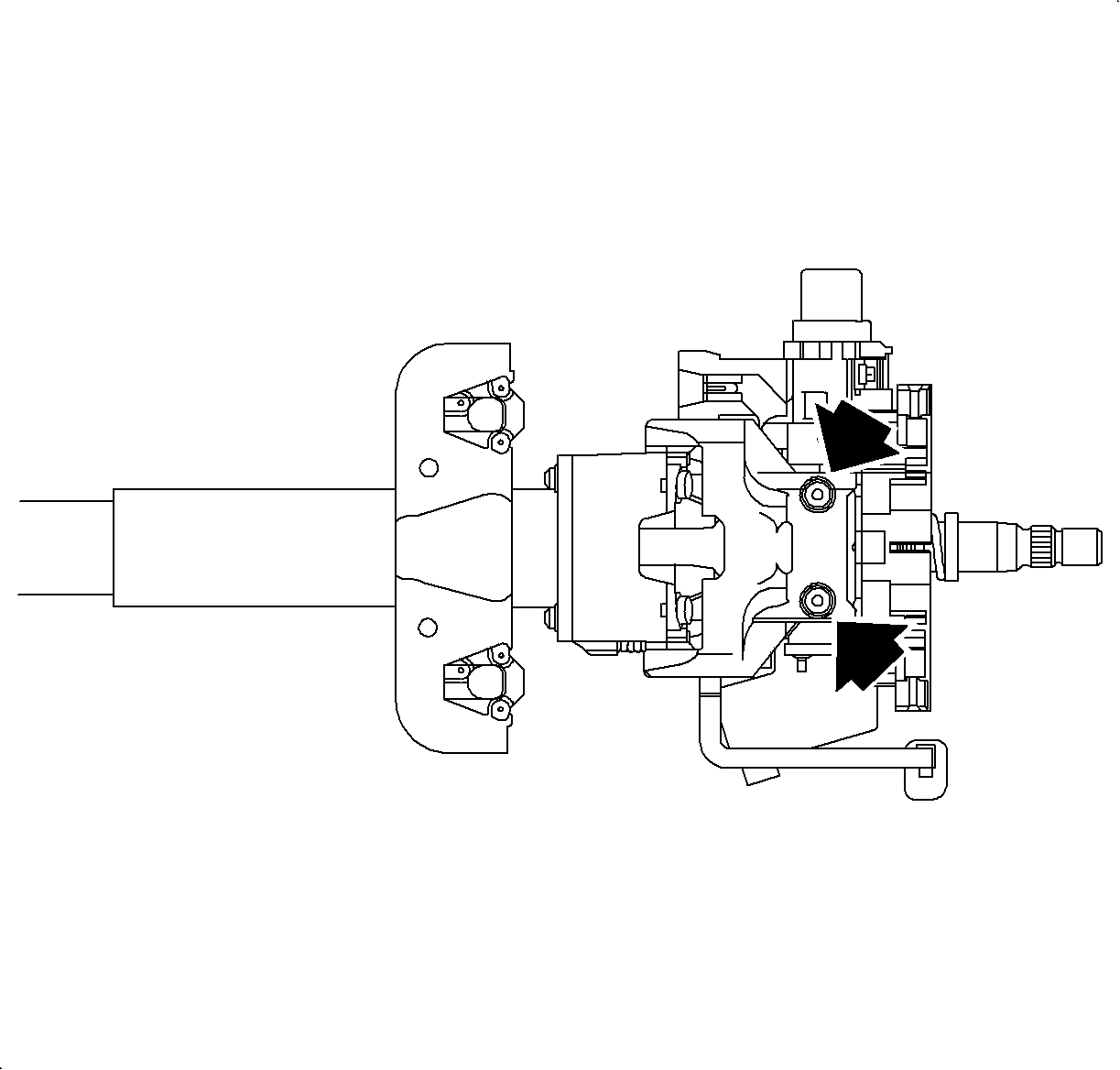
- Remove the ignition module shear bolts.
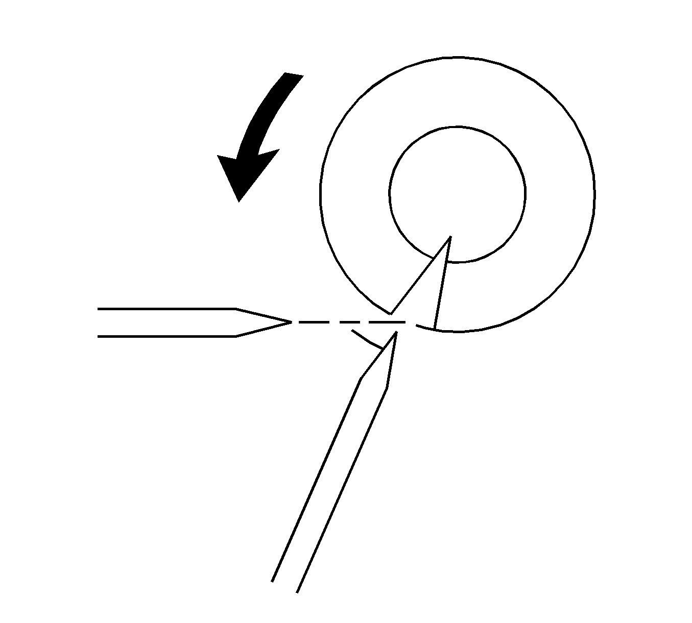
- Use a light hammer and a chisel to bite into the shear bolt head at a position offset from its center.
- Tap the chisel to rotate the bolt and loosen it.
- Repeat until the bolt is loose enough to remove.
- Remove the ignition module assembly from the steering column.
Important: The passlock sensor is part of the ignition module.

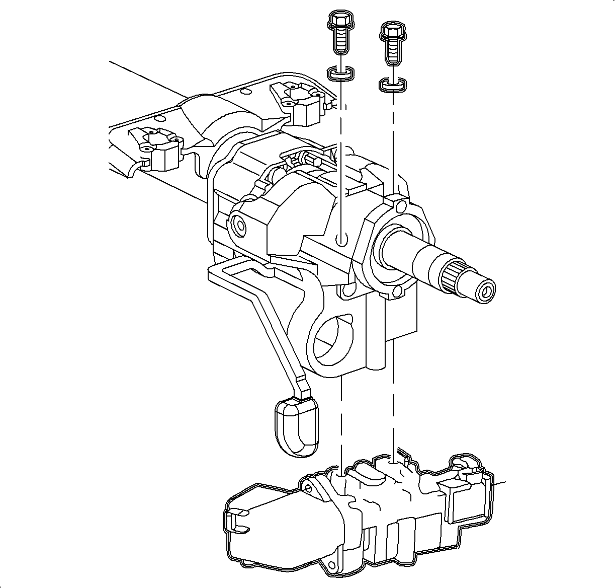
Installation Procedure
- Use the new shear bolts to install the ignition module assembly on the steering column. Tighten the shear bolts until the heads break off.
- Install the turn signal/headlamp lever, the windshield washer lever, and the passlock sensor connector.
- Install the park lock solenoid.
- Install the ignition switch and reconnect the ignition switch connector.
- Install the shroud fasteners and the steering column lower shroud panel.
- Insert the key into the ignition lock cylinder and install into the ignition module.
- Install the steering column upper shroud panel.
- Install the lock cylinder bezel.
- Enable the SIR system. Refer to Enabling the SIR System in SIR.


Tighten
Tighten the park lock solenoid screws to 1.5 N·m (14 lb in).

Tighten
Tighten the ignition switch fasteners to 1.5 N·m (13 lb in).

Tighten
Tighten the steering wheel shroud fasteners to 3 N·m(27 lb in).
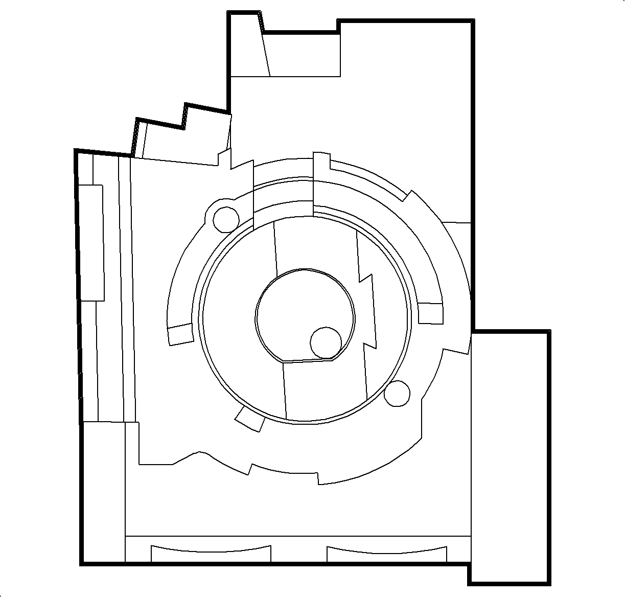
Important: The actuator blade within the ignition module housing must be in the RUN position to install the lock cylinder assembly. If rotated, replace it to the RUN position using needle nose pliers.

