HVAC Control - Standard HVAC

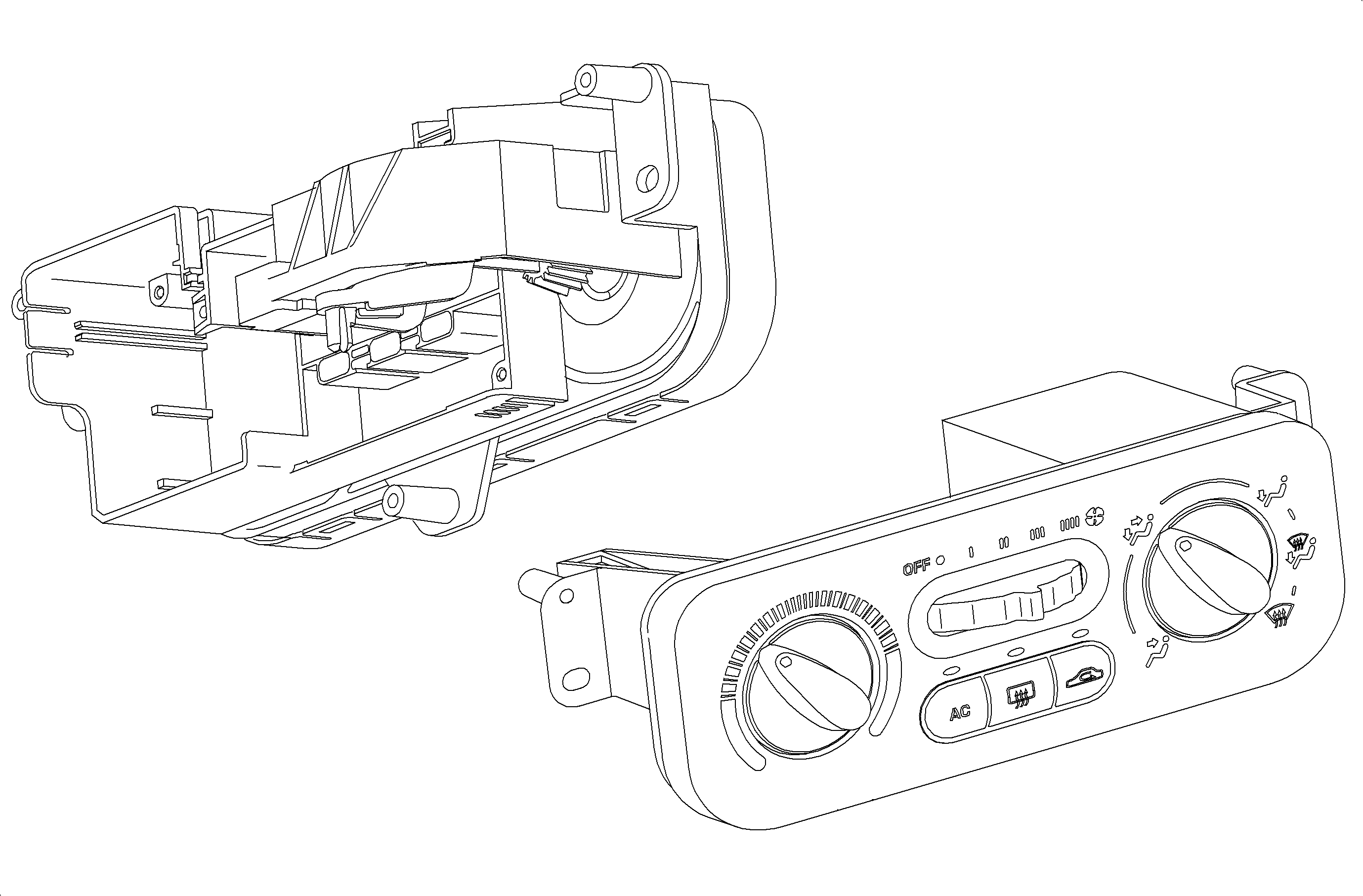
The operation of the A/C and heating system is controlled by the buttons, rotary switch, and knobs on the HVAC control head. The compressor clutch, rear defog and recirc motor are controlled electrically by push buttons on the control head.
Blower speeds are controlled in all modes by a 5 position rotary switch. The blower motor and compressor are not operational when the blower switch is in the OFF position.
The temperature knob controls the temperature door through a cable from the HVAC control assembly to the HVAC module. The mode knob controls the various mode positions using an actuator located on the HVAC module.
The control head logic will automatically select outside air and A/C whenever defrost and heater/defrost is selected, regardless of the A/C and recirculation button position.
HVAC Module - Standard HVAC

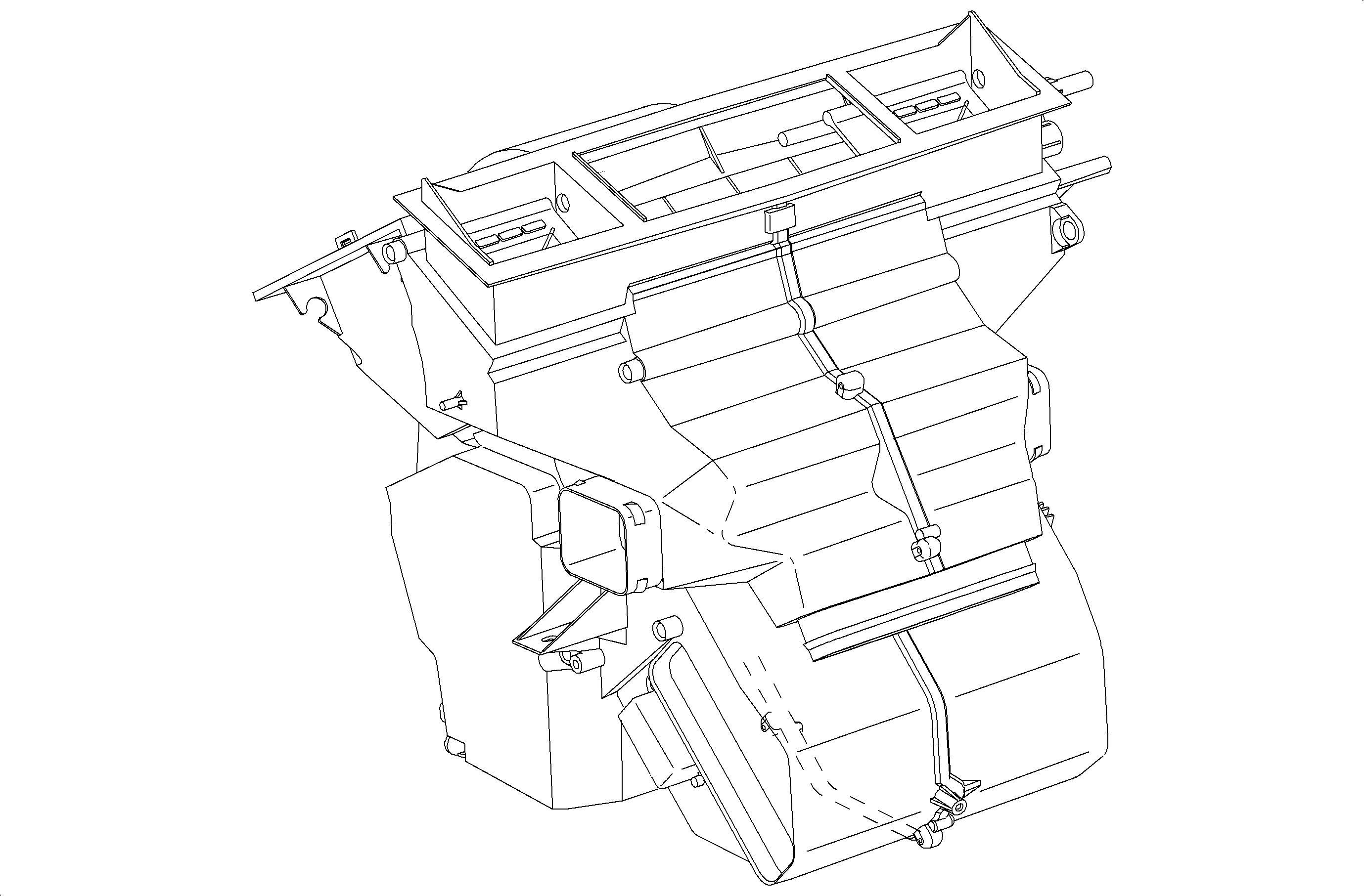
The HVAC module consists of a recirc actuator, a mode actuator, blower motor and fan, a blower motor resistor, a heater core, and an evaporator core. The operations of these assemblies are controlled by the knobs and switches on the HVAC control panel.
Distribution of the air is controlled by the mode knob and buttons on the control assembly. The various positions of the mode knob and buttons direct cooled, heated, blended, outside, or inside air through the air ducts. The flow of air during the various modes of operations is as follows:
| • | Face - Instrument panel outlets |
| • | Face and Feet - Instrument panel outlets and floor outlets |
| • | Feet - Floor outlets with a small amount of bleed air to defroster |
| • | Feet/Defrost - Floor outlets and defroster with slight bleed to instrument panel outlets |
| • | Top - Defroster ducts with small amount of air to side window defoggers |
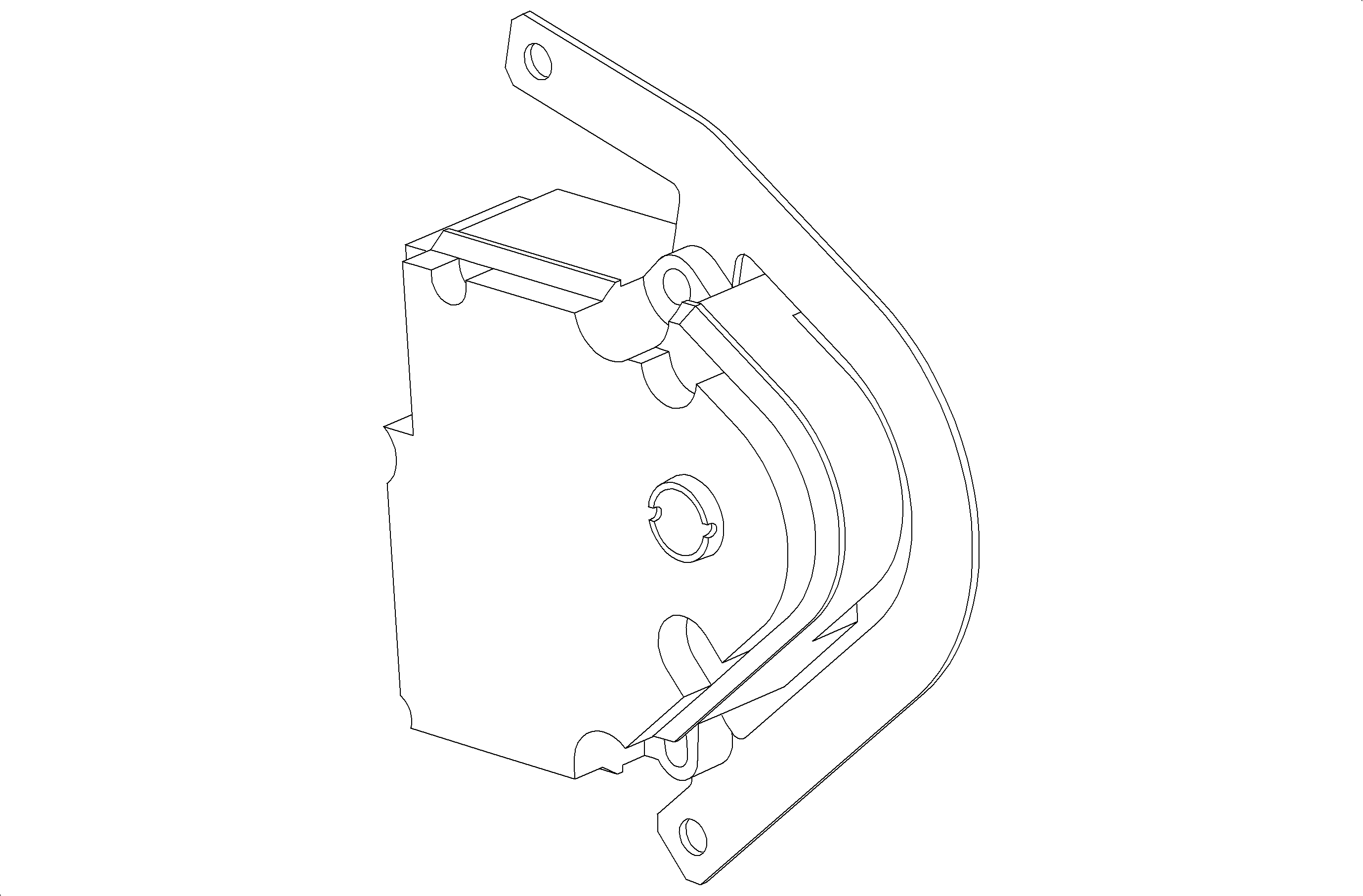
Mode Actuator

The mode actuator allows the operator to control the location of airflow into the passenger compartment. The mode actuator rotates a cam to open and close the defrost, heater, and vent doors to direct air to the location selected.
Blower Motor Resistor Card - Standard HVAC

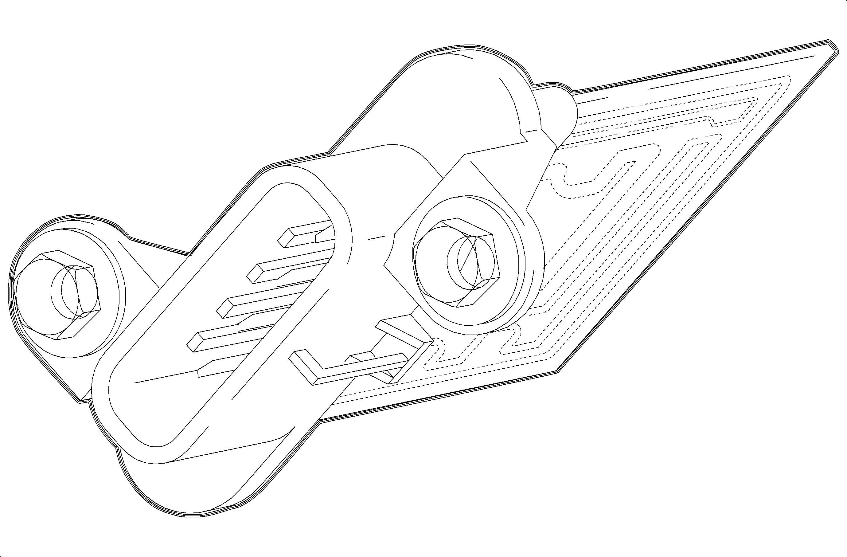
The blower motor resistor card is located on the right side of the HVAC module forward of the re-circulation actuator. The resistors located on the card lower the blower motor voltage to create the Low, M1, and M2 speeds. The resistor card has a fusible link which if blown, will require that the card be replaced.
The blower motor will still operate in High when the fusible link is blown.
