| Table 1: | Noise Entry Conditions |
| Table 2: | Symptom Table - Noise and Reception Performance Complaints |
| Table 3: | Noise Diagnostic Filters |
| Table 4: | RFI Diagnostic Worksheet |
| Table 5: | RFI Identifying Chart |
Important: The purpose of the System Performance Check is to distinguish between noise or poor reception. Some noises induced into the system may not be audible but can cause poor reception. All reception and noise listening should be done outside, away from electrical interference -- power lines, buildings, etc. The hood should also be closed.
Action | Normal Results | Cause and Solutions |
|---|---|---|
|
Important: Radio frequency interference (RFI) can cause a fewer number of stations to be received in one of the three modes. The RFI can be caused by various vehicle components. This may be the cause of the difference in reception. Check for components powered up in the three various key positions. This may eliminate engine running components, ignition on components, etc. For example, if the same number of stations are received with the engine running as when the engine was off, the components active with the engine running are not causing the interference. Refer to RFI Questionnaire and Diagnosis. | ||
Ignition in ACC position, radio ON | -- | -- |
Seek up (87.7-107.9 FM) (550-1710 AM) Count number of valid Radio Stations the tuner stops at. Listen for various noise problems. | A certain number of radio stations will be received. Sometimes the radio will stop at dead spots on the display where there is no audible information. These dead spots should not be counted as valid stations. | -- |
Ignition On, engine Off Repeat step 2. | Same results as step 2 | If you do not get the same results as step 2, suspect noisy electrical component (refer to Chart 14, Radio Noise). |
Ignition On, engine running Repeat step 2. | Same results as step 2 | If you do not get the same results as step 2, suspect ignition fuel injector or other engine related system (refer to Chart 14, Radio Noise). |
With the radio playing on a "noisy" station, slowly move the radio out from the H-brace. | If Sideway noise is present, the noise will get quieter. | Sideway noise can be caused by wiring or metal cables near the radio. (Reroute wiring or wrap wires with aluminum or nickel tape to shield.) Connect shield to ground. |
With the radio playing on a noisy station, unplug the antenna from the back of the radio. Customer complaint may be ignition noise on AM only. | If Frontway noise is present, the noise will be eliminated. | Frontway noise can be caused by poor antenna grounding (see Antenna System Check) or poor radio case ground. Check braided ground wire between the radio case and the H-brace (see Ground Strap Check). Other causes include defective relays, solenoids, switches, poor ground of hood. Or something near the coax cable or corrosion at antenna coax connection. |
If the noise is not sideway or frontway and is still heard at minimum volume, then Backway noise is present. | Backway noise may be related to other harnesses and could be intermittent depending on the component that is causing it. | Read the IMPORTANT note below. Suppression can be installed at the source (as close as possible is preferable), the radio, or both. Pops are best suppressed with a capacitor. Squeals and buzzes are best suppressed using filters. |
Noise Diagnosis - Four Ways Noise Can Enter a Radio System and The Typical Causes
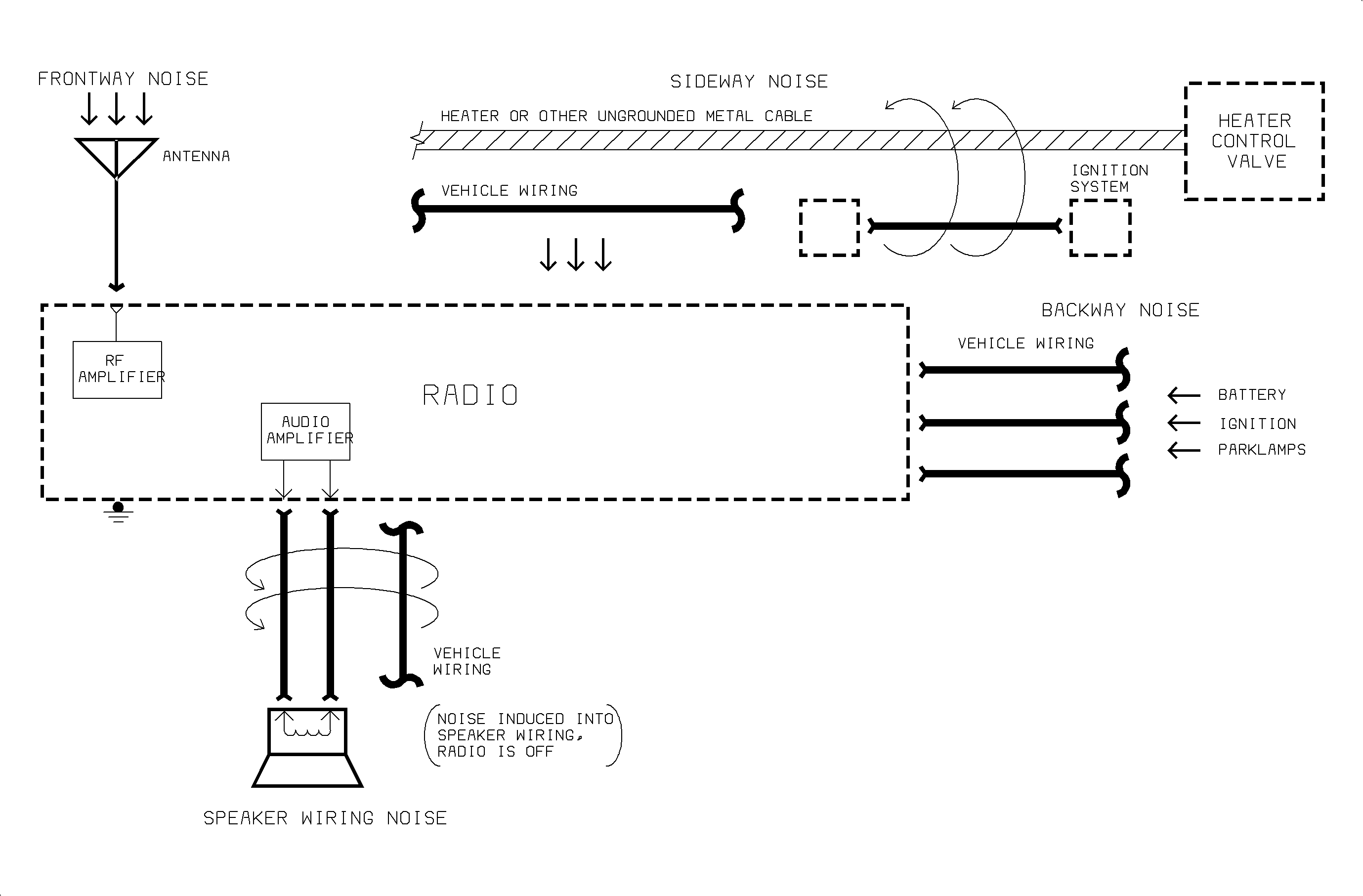
Frontway Noise
| • | Hood ungrounded or poorly grounded |
| • | Antenna lead-in or antenna base poorly connected or corroded |
| • | Defective secondary ignition system |
| • | Poor grounding of relays, solenoids, switches, the receiver, or body parts |
Sideway Noise
| • | Ungrounded cables near radio, transmitting noise |
| • | High current or noisy wires near radio, transmitting noise |
Speaker Wiring Or Harness Noise
| • | Noisy wires routed too close to speaker wires |
| • | Pinched, broken, or shorted audio wires |
| • | Defective connectors or speakers |
Backway Noise
| • | Electrical components noisy or defective |
| • | After-market devices improperly installed |
| • | Vehicle wiring ground connection poor or corroded |
| • | Receiver poorly grounded |
Symptom | Procedure |
|---|---|
To distinguish between noise or poor reception, perform the System Performance Check. Important: All reception and noise listening should be done outside, away from electrical interference -- power lines, buildings, etc. The hood should also be closed. | |
Noise present when using power windows. | Refer to Static Noise below. |
Popping noise present when playing a cassette. | Refer to Popping Noise below. |
Poor reception | Go to Chart 13. |
Radio noise | Go to Chart 14. |
Radio noise entering through radio (sideway noise). | Go to Chart 15. |
Radio noise entering through harness (backway noise) while engine not running. | Go to Chart 16. |
Radio noise entering through harness (backway noise) while engine running only. | Go to Chart 17. |
Radio noise entering through antenna system (frontway noise). | Go to Chart 18. |
Engine electrical noise | Go to Chart 19. |
Secondary ignition noise (from spark plugs or wires) | Go to Chart 20. |
Speaker harness related noise | Go to Chart 21. |
Switch pop or accessory noise | Go to Chart 22 |
Static Noise
Some customers may comment that a static noise can be heard while listening to AM radio stations during operation of a front door power window. The static may be louder on weaker AM stations or when the door is open and the power windows are operated. This condition may be caused by an insufficient ground path from the front door power window motor to the body ground plane.
The corrective action to this condition is to install a ground wire, from the front door power window motor housing through the wiring harness door grommets to the center instrument panel reinforcement. To locate bulletins pertaining to Radio Noise, search technical bulletin index.
Popping Noise
An intermittent popping noise from the radio speakers may be heard when playing an audio cassette with a cellular phone powered On and the cellular phone antenna in the vehicle. The condition may occur, with phone powered On, whether or not a call is taking place.
This is caused by the antenna on the cellular phone being too close to the radio. The cellular phone sends electrical impulses that get amplified by the radio. This occurs when the cellular phone receiver switches cells or power levels.
Inform the customer that an EXTERIOR clip-on or window glue-on type cellular phone antenna instead of an interior cellular phone antenna MUST BE used. Exterior mounted cellular phone antennas are available from cellular phone retailers.
Saturn Part Number | Description | Value |
|---|---|---|
01224205 | Filter Pack - Radio Noise | 250 mh, 330 v cap |
01227895 | Filter Pack - Radio Noise | 220 [micro ]F, 50 v cap |
01227894 | Filter Pack - Radio Noise | 0.47 [micro ]F, 200 v cap |
Chart 13
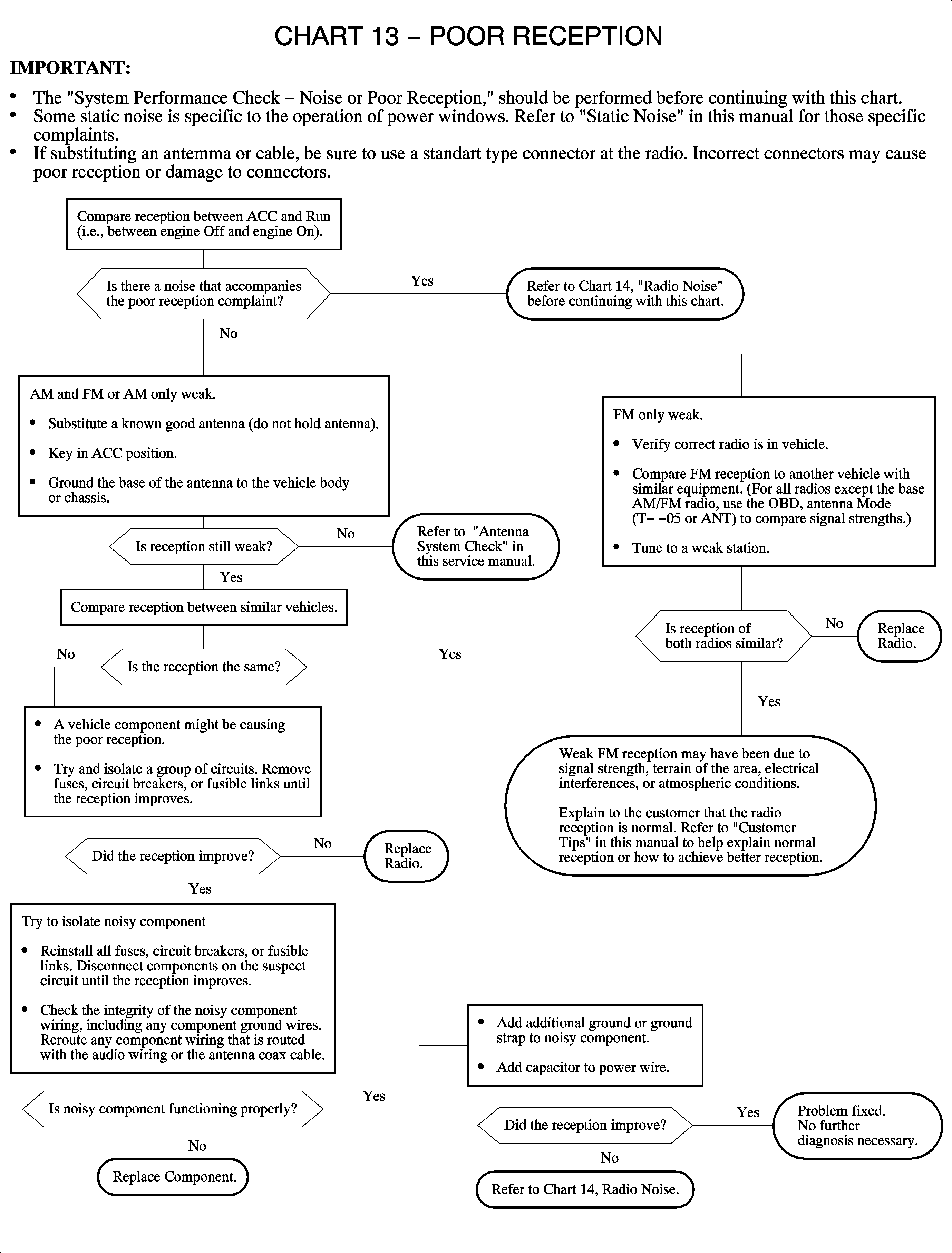
Chart 14
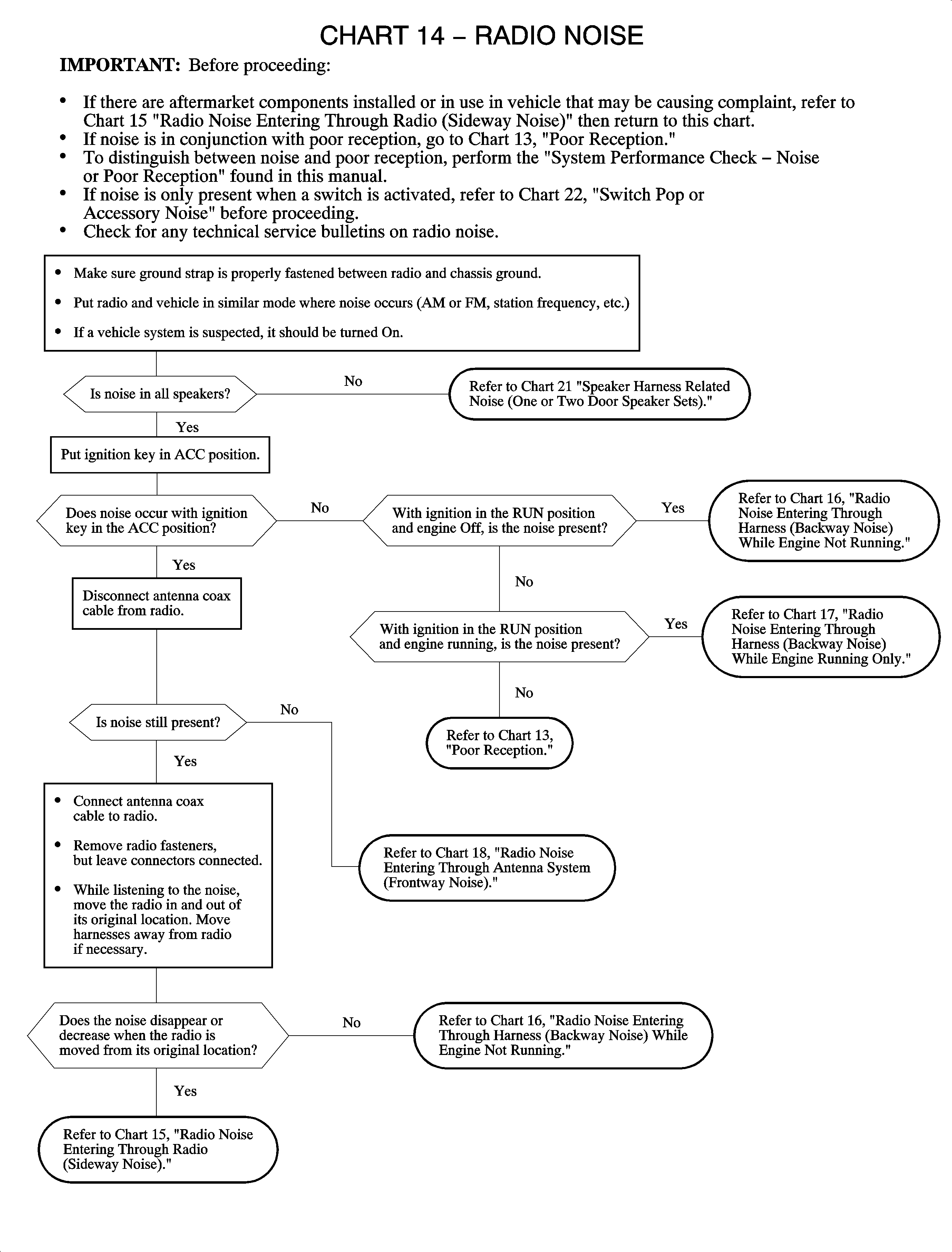
Chart 15
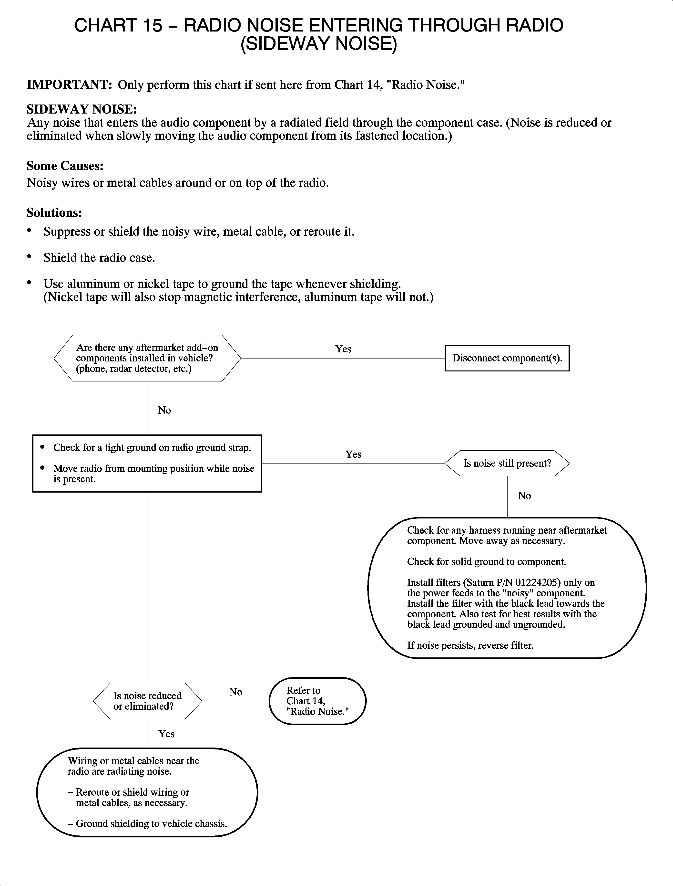
Chart 16
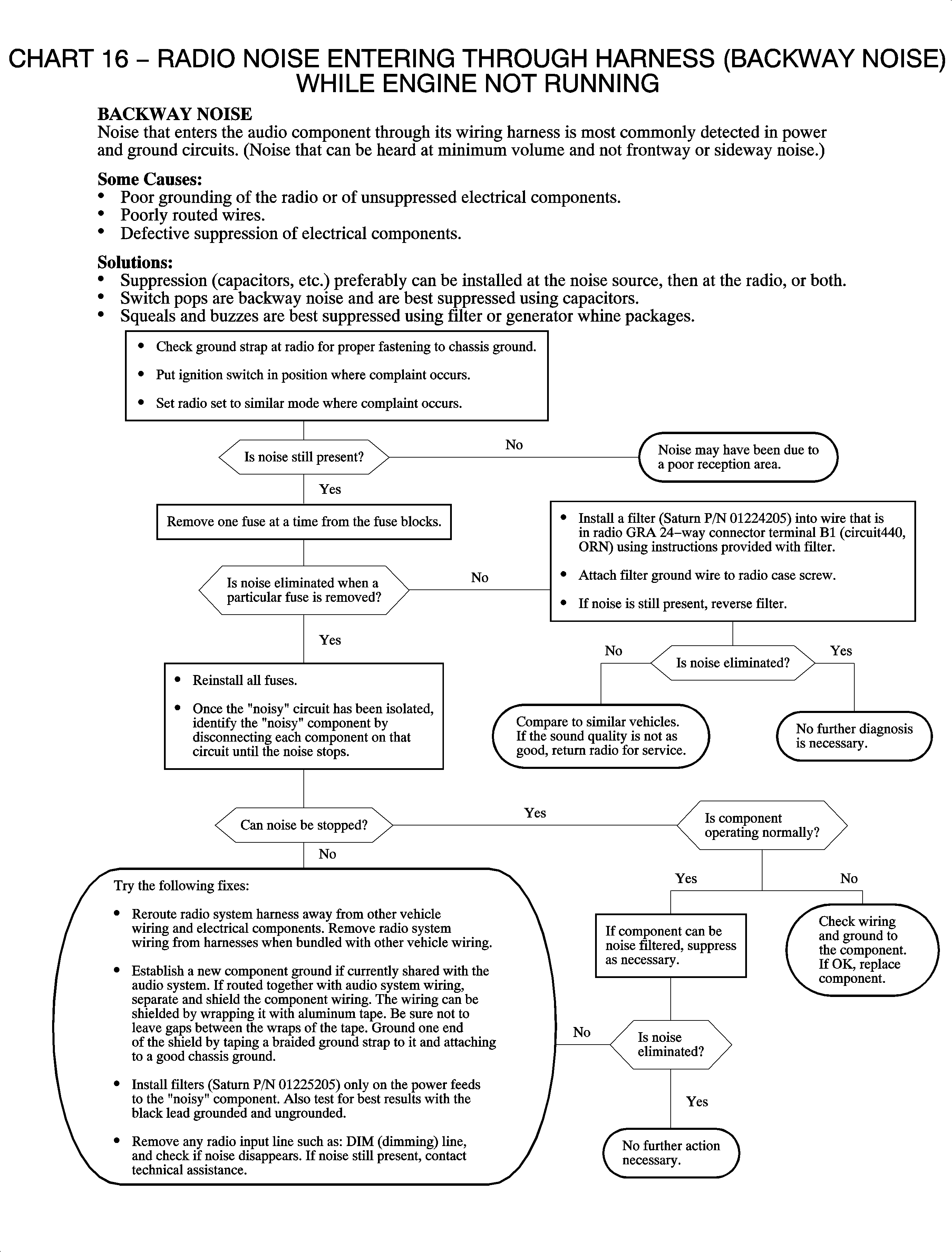
Chart 17
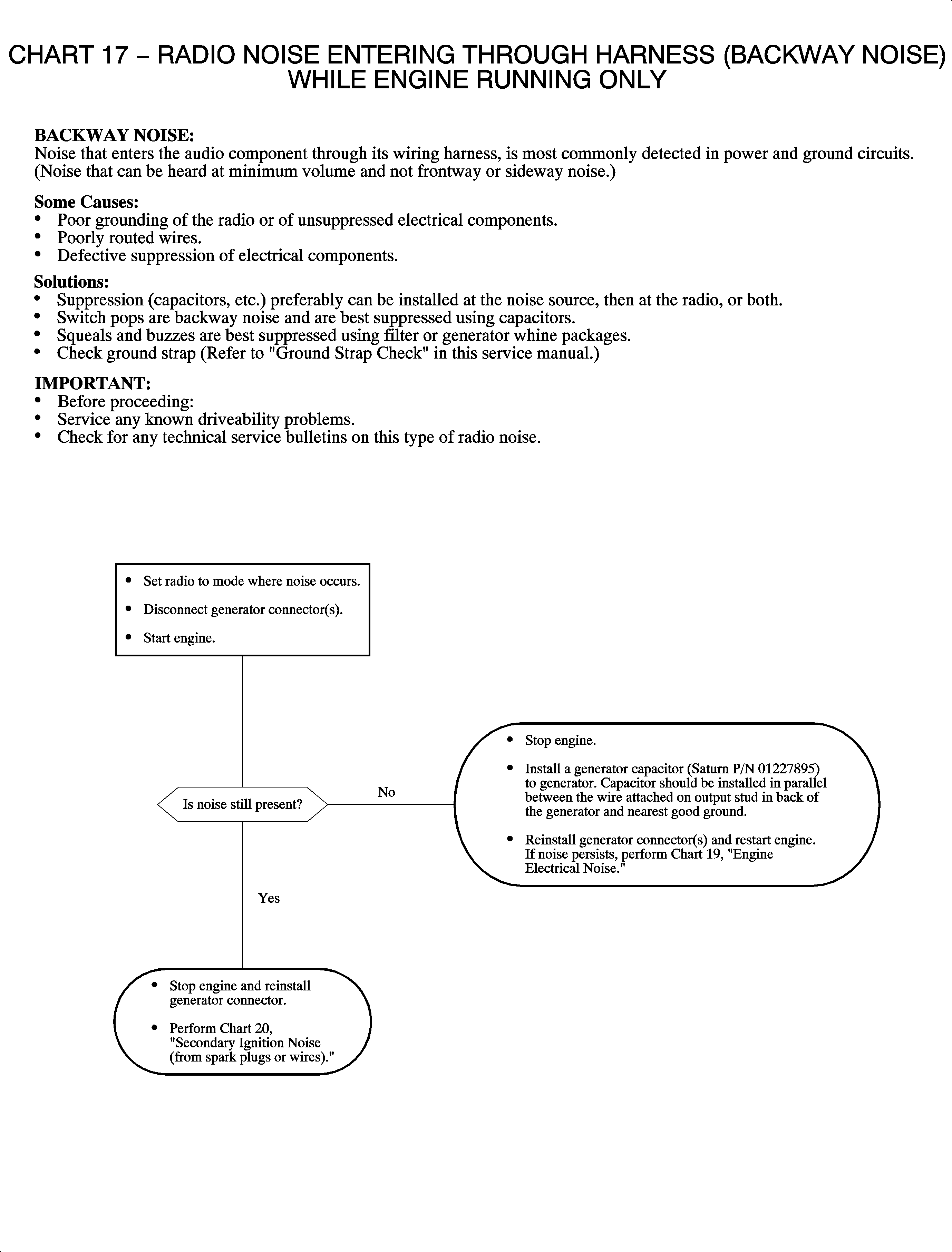
Chart 18
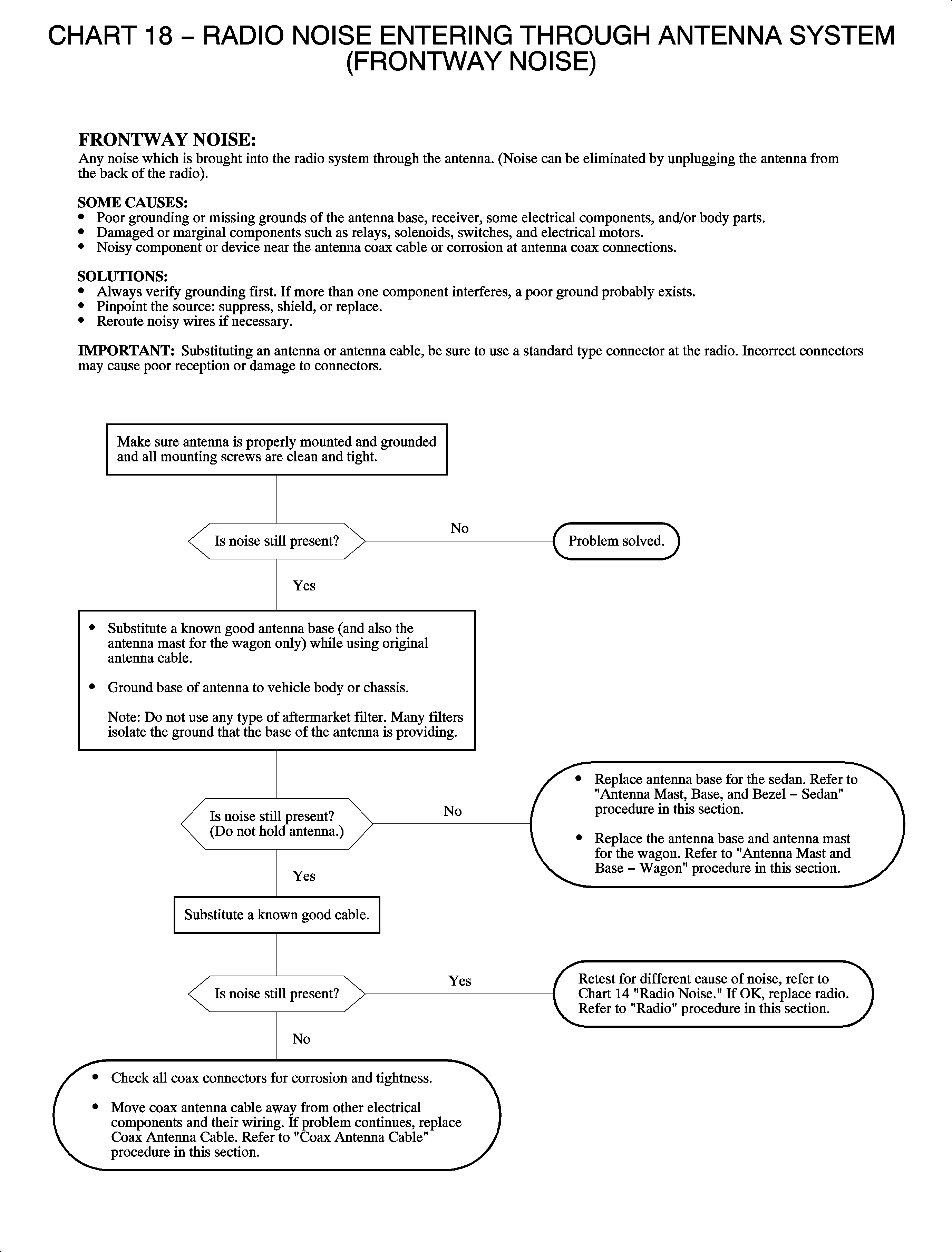
Chart 19
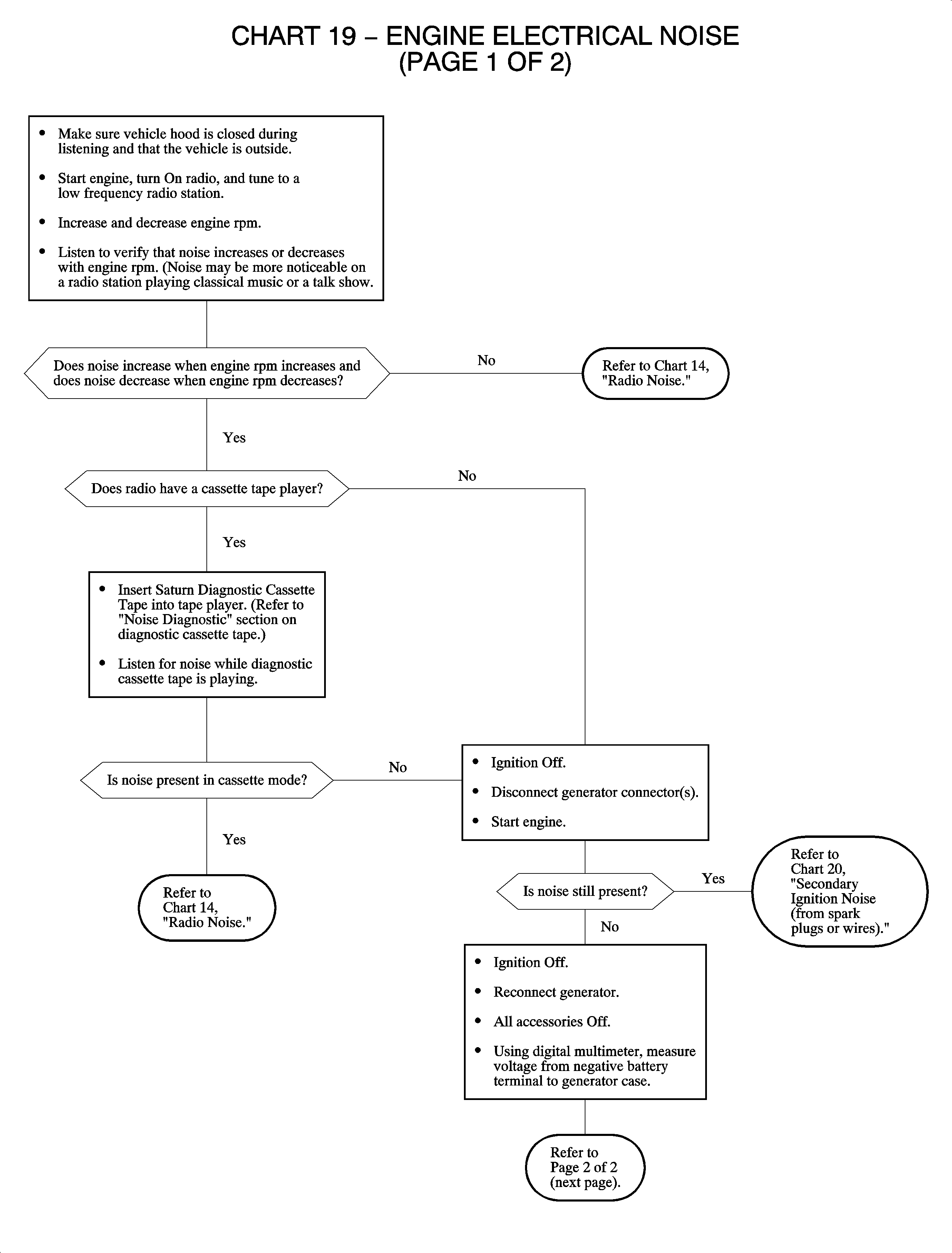
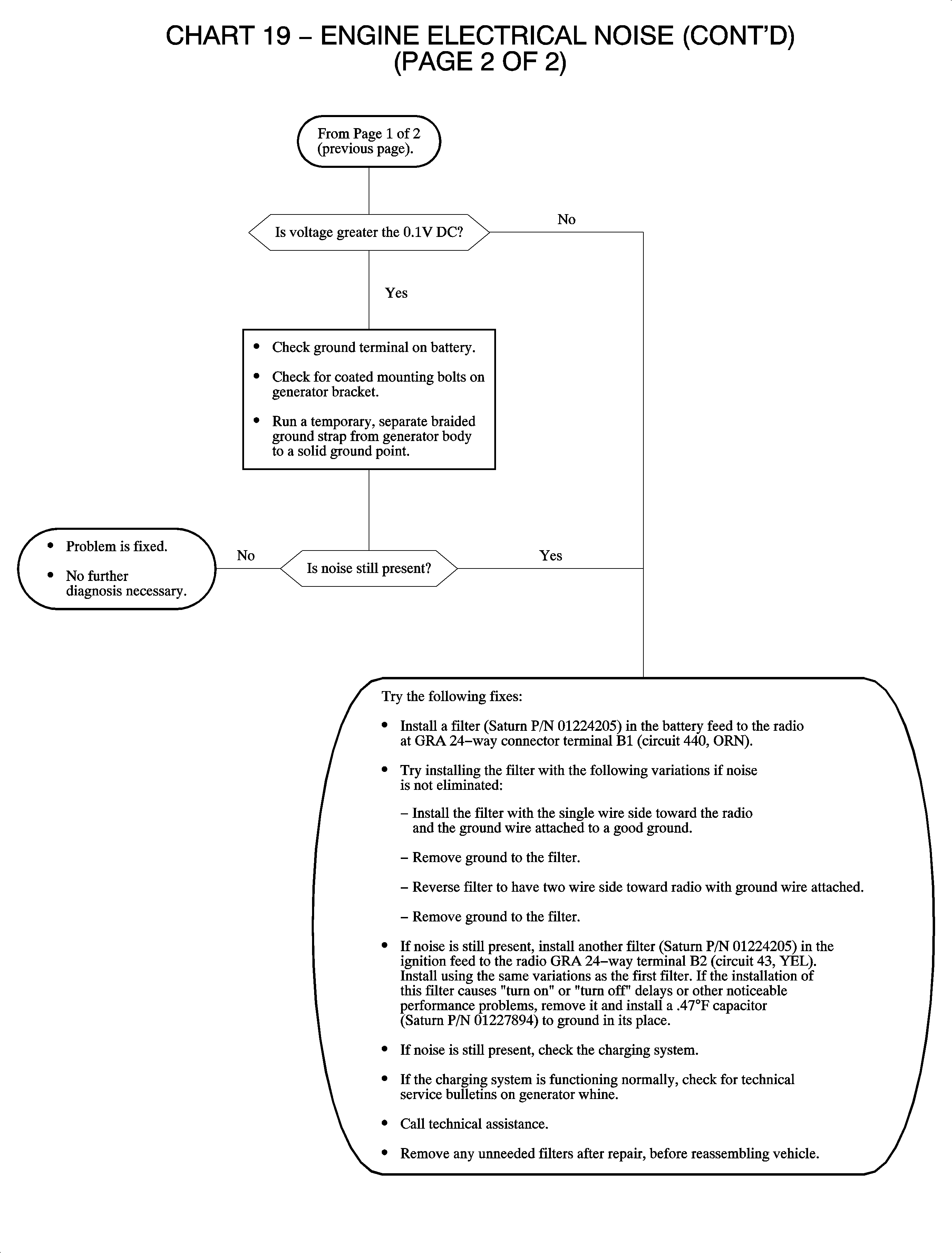
Chart 20
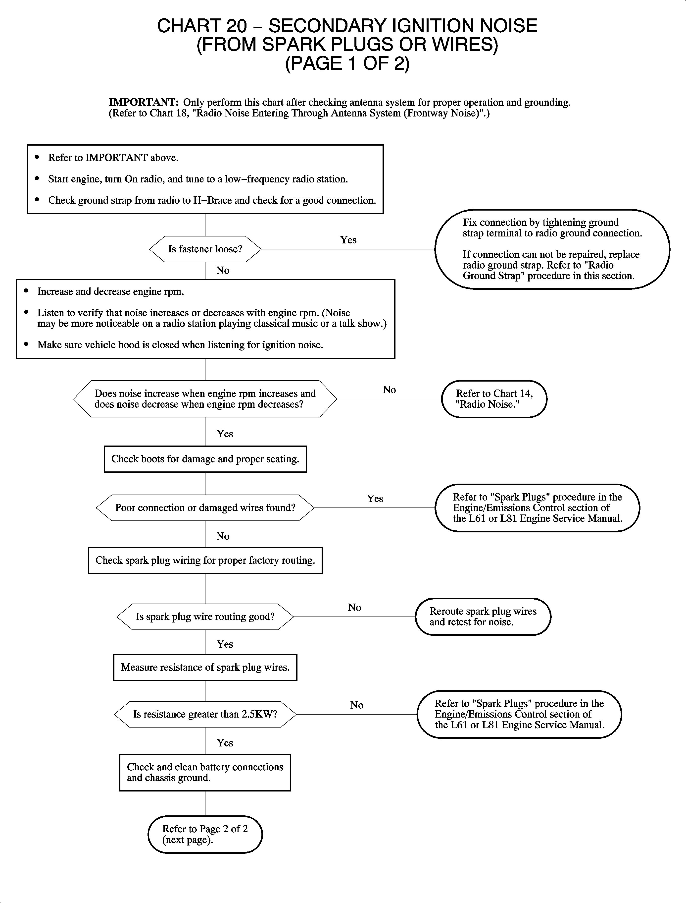
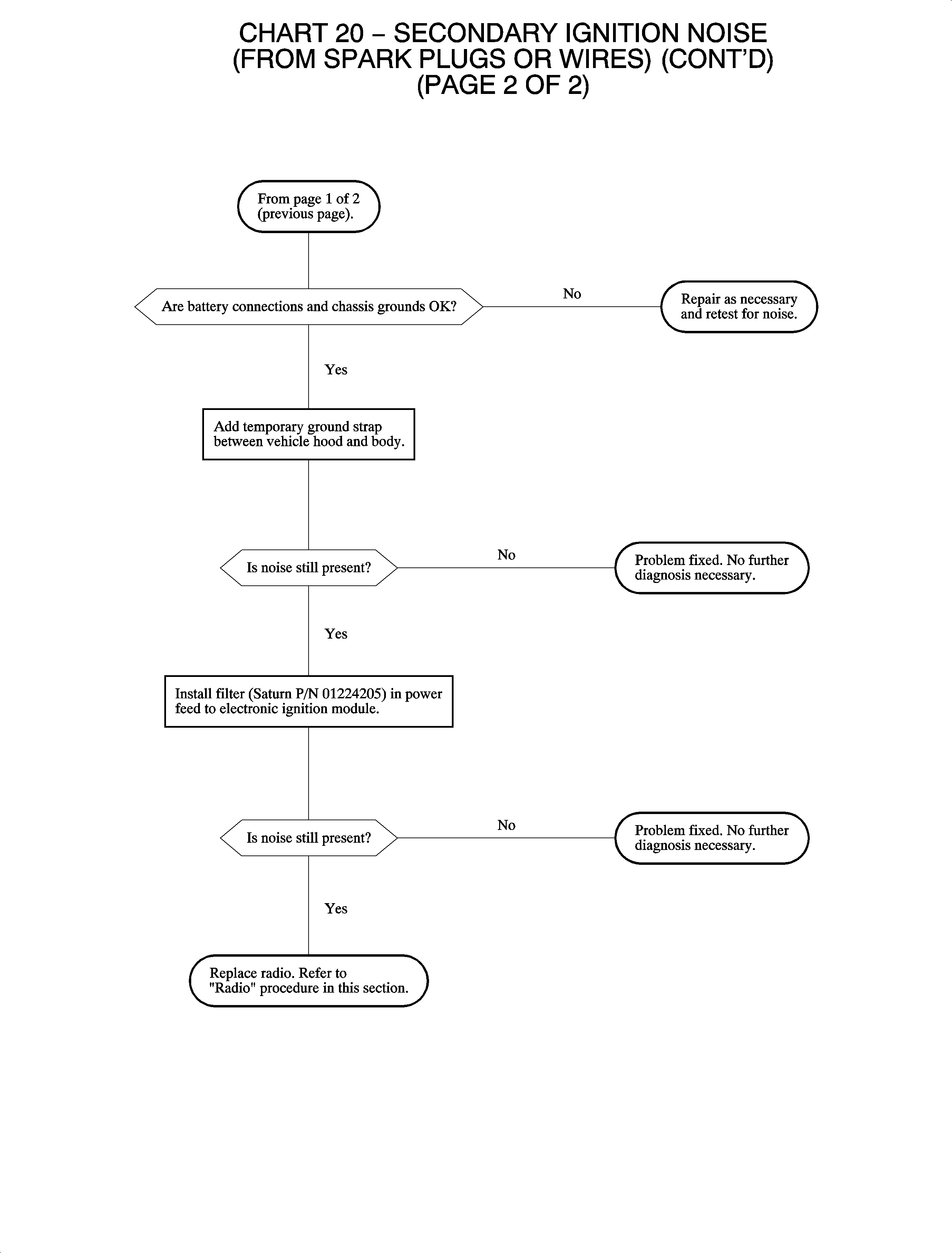
Chart 21
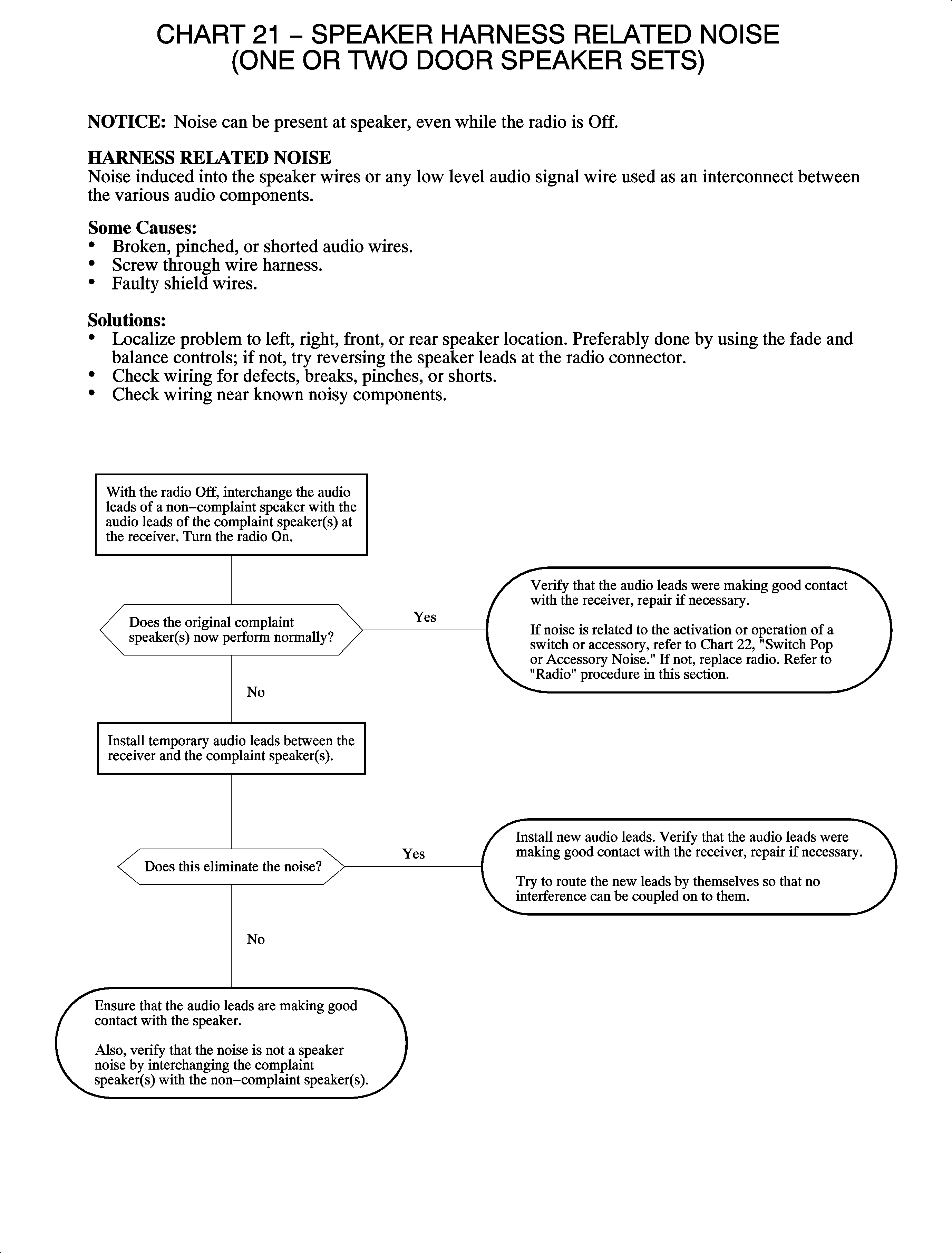
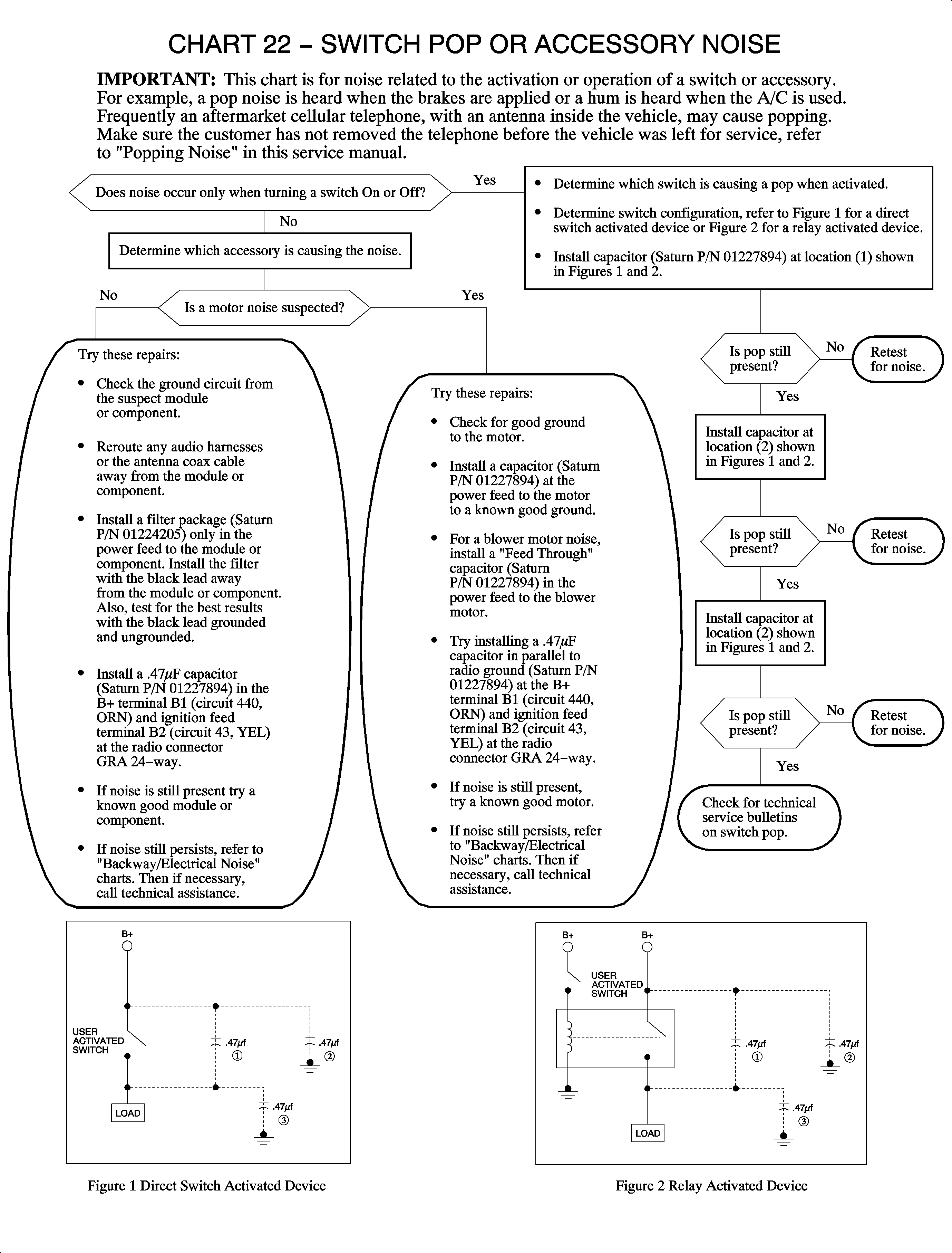
Chart 22
RFI-Radio Frequency Interference
The purpose of this information is to help in the identification and diagnosis of radio frequency interference (RFI). RFI complaints may include noises, interference, static, whines, pops, and poor reception of stations normally receivable by the radio system. These complaints may also apply to any two-way communications radio installed in the vehicle including HAM, police, fire, business band, and cellular phones. RFI can occur as a fading signal or noise superimposed on a tuned signal.
RFI is the undesirable disturbance of an electrical system or device with another electrical system or device. The following questionnaire and diagnostic charts will help identify if there is an RFI problem in the vehicle.
Step | Question | Yes | No | ||||||||||||||||||||||||||||
|---|---|---|---|---|---|---|---|---|---|---|---|---|---|---|---|---|---|---|---|---|---|---|---|---|---|---|---|---|---|---|---|
|
Important: To begin diagnosing RFI conditions, it is important to understand the nature of the condition and the elements that may be involved. The following questionnaire will help determine vital pieces of information for the diagnostic process. Filling out this questionnaire, allows you to use the diagnostic charts on the following pages in a more efficient manner. | |||||||||||||||||||||||||||||||
1 | Is the vehicle equipped with any non-factory installed electronics? This includes: radar detectors, scanners, and hand-held communications devices. |
|
| ||||||||||||||||||||||||||||
2 | If the condition occurs with a non-factory installed radio, have the radio installation guidelines been followed? |
|
| ||||||||||||||||||||||||||||
3 | If the concern is with the entertainment radio, is the tape or CD affected? |
|
| ||||||||||||||||||||||||||||
4 | Identify when the condition occurs:
Does the condition persist? |
|
| ||||||||||||||||||||||||||||
5 | If the condition is related to a fleet vehicle, answer the following:
|
|
| ||||||||||||||||||||||||||||
RFI Determination and Identifying Chart
This chart is to be used along with the diagnostic charts to help determine if the condition is RFI related and to help identify what electronic device in the vehicle is interfering with the radio. Make sure the information in the questionnaire is as accurate as possible. You MUST be able to duplicate the customer's concern to diagnose RFI conditions. The process of identifying RFI and the source of an interference is simply the process of elimination. When the source of the interference is disconnected from power, the radio will work properly.
Box | Condition |
|---|---|
1 | Verify that the condition is present, then disconnect any non-factory, add-on electronics -- not including the radio. If the non-factory, add-on electronics can be switched Off then On, it may not be necessary to disconnect these devices. |
2 | If the condition goes away when a particular device is disconnected, reconnect the device to verify it as the source of the interference. If the condition is related to non-factory, add-on electronics, consult the installation guidelines -- refer to Box 6 in this chart -- as an example of how to add an electronic component to the vehicle's electrical system. |
3 | If the condition is ONLY present with the engine running, disconnect electrical components that are active only with the engine running. The charging system, various solenoids, and relays may be intermittently disconnected while observing the condition. In some cases, a component cannot be disconnected while the engine is running. In these cases, the component can be tested independent of the vehicle, e.g., fuel injectors. |
4 | If the condition can be eliminated and the interference isolated to a component, determine if a technical information bulletin has been published concerning this particular condition. Contact the Technical Assistance Center for additional information if no bulletins are found. |
5 | If the identified concern cannot be eliminated by testing in any key position and by disconnecting fuses and components, check for published technical information bulletins. If the concern cannot be identified or eliminated, contact the Technical Assistance Center for further assistance. |
6 | The installation guidelines for aftermarket accessories for all model years is located in the Technical Information Bulletin, "Information On Installation of Cellular Telephones and/or Other Electrical Accessories in Saturn Vehicles." For speaker pop, refer to Popping Noise. |
Chart 23
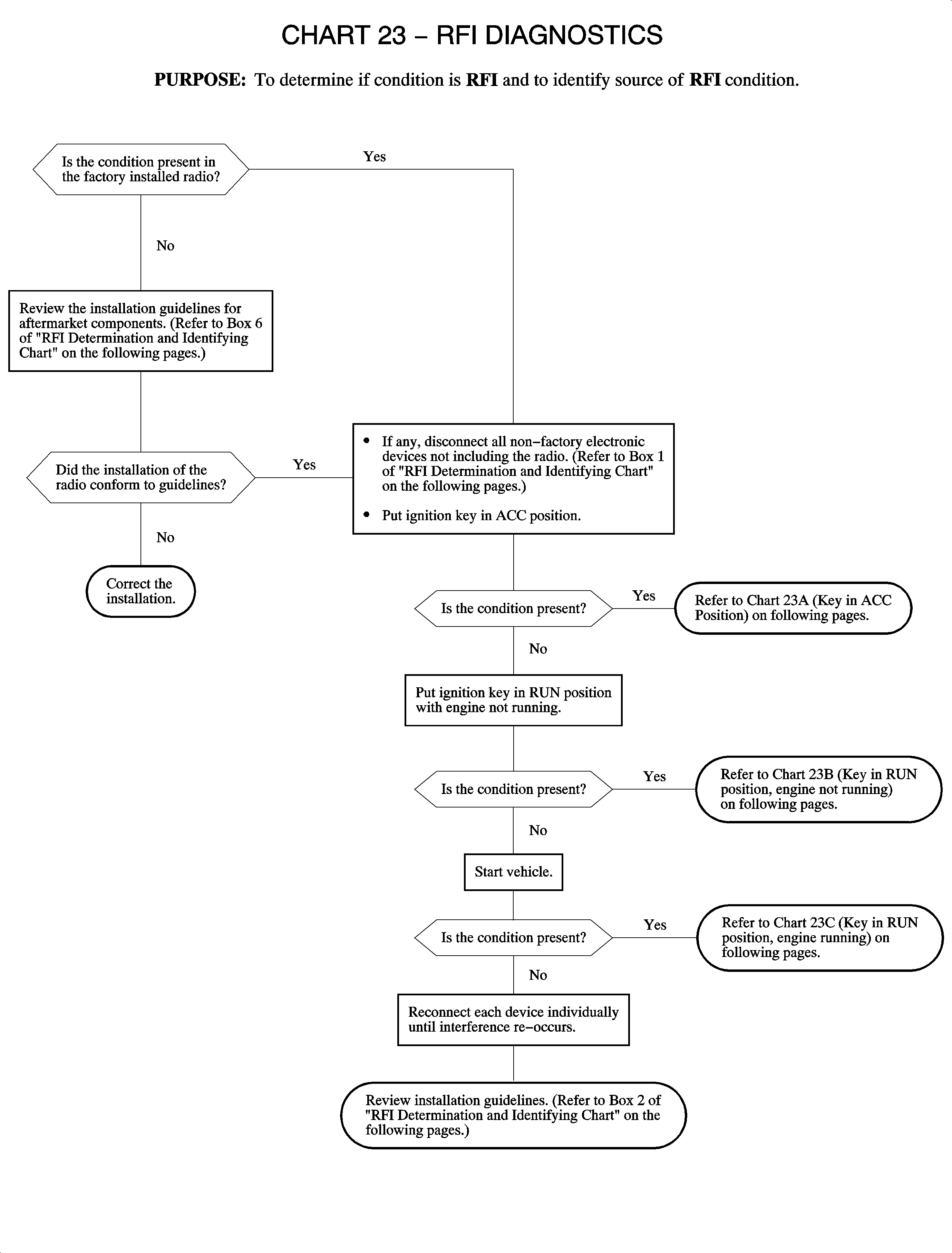
Chart 23A
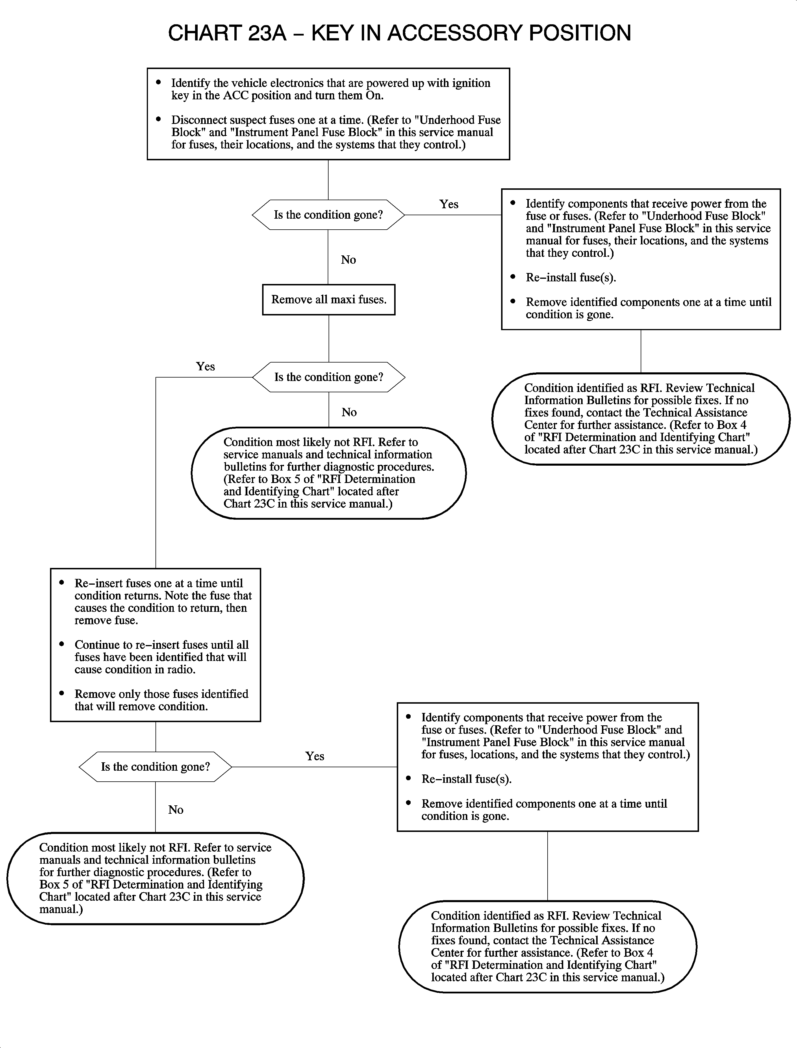
Chart 23B
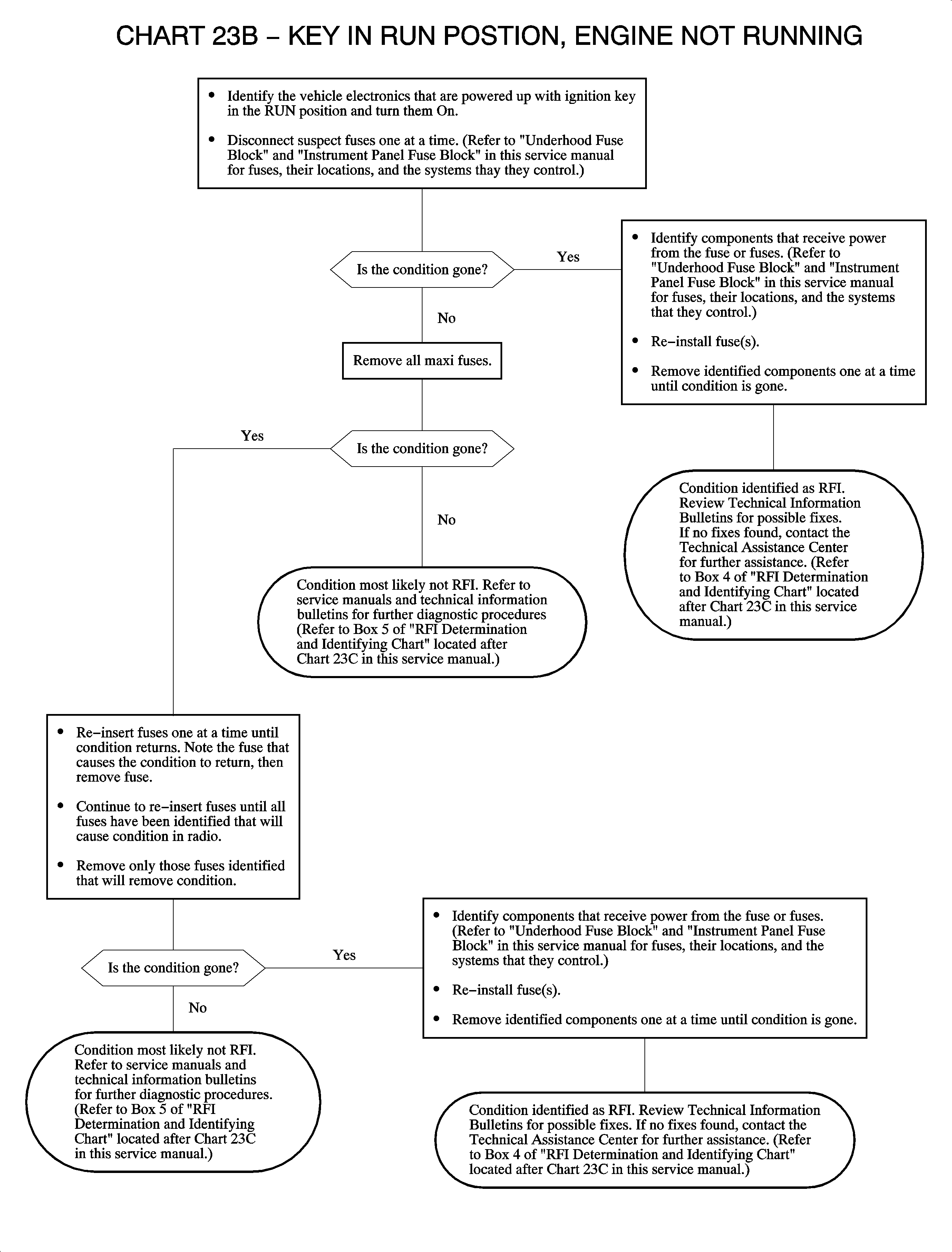
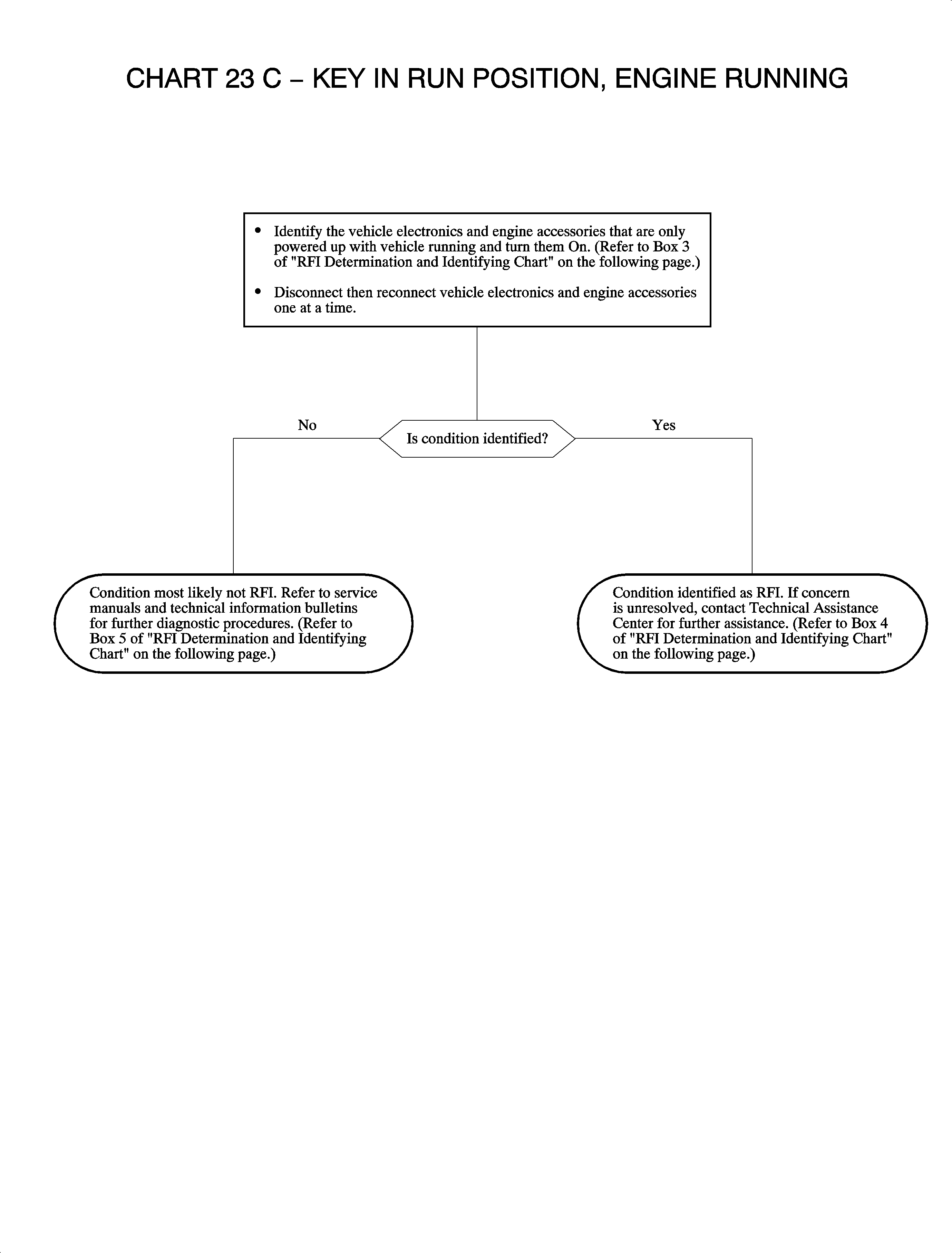
Chart 23C
